Hardware Maintenance Manual
Page 9
... System card data 23 PCI routing 23 Devices and I/O ports 23 Date and time 24 System security 24 Using the power-on password menu . . . 26 Using the administrator password menu . 27 Defining a system owner's name . . . . . 28 Start options 29 Advanced setup 29 Core chipset control 29 PCI bus control 30 Cache control 30 Memory settings 30 Advanced ISA settings 30 Service Processor IRQ settings . . . . . 30 Plug and Play 31 Error log 31 Configuring PCI features and options . . . . 31 Configuring the Ethernet controller 32 Ethernet controller...
... System card data 23 PCI routing 23 Devices and I/O ports 23 Date and time 24 System security 24 Using the power-on password menu . . . 26 Using the administrator password menu . 27 Defining a system owner's name . . . . . 28 Start options 29 Advanced setup 29 Core chipset control 29 PCI bus control 30 Cache control 30 Memory settings 30 Advanced ISA settings 30 Service Processor IRQ settings . . . . . 30 Plug and Play 31 Error log 31 Configuring PCI features and options . . . . 31 Configuring the Ethernet controller 32 Ethernet controller...

Hardware Maintenance Manual
Page 10
... format 54 Verifying the disk media 54 Locations 55 Adapters 56 Adapter considerations 56 Installing or removing adapters 57 Battery 61 Bays 64 Types of cables 65 SCSI devices 66 SCSI IDs 66 Termination requirements 67 Preinstallation steps (all bays 67 Installing or removing drives in bays A and B (removable media 69 Installing or removing a drive in bay C (diskette drive 70 Installing or removing drives in bays 1 through 5 (hard disk drives 72 Changing jumper positions 75 Two-pin jumper blocks 75 Completing...
... format 54 Verifying the disk media 54 Locations 55 Adapters 56 Adapter considerations 56 Installing or removing adapters 57 Battery 61 Bays 64 Types of cables 65 SCSI devices 66 SCSI IDs 66 Termination requirements 67 Preinstallation steps (all bays 67 Installing or removing drives in bays A and B (removable media 69 Installing or removing a drive in bay C (diskette drive 70 Installing or removing drives in bays 1 through 5 (hard disk drives 72 Changing jumper positions 75 Two-pin jumper blocks 75 Completing...
Hardware Maintenance Manual
Page 11
... U-bolt and security cable . . . . 139 Serial port connectors 141 System board illustration 142 System board LEDs 142 System board connectors 143 System board removal/replacement 145 System board switches 147 Bypassing an unknown power-on password 148 Universal serial bus ports 149 Updating the server configuration 150 Video port connector 151 Symptom-to-FRU index 152 Beep symptoms 152 No beep symptoms 155 Diagnostic error codes 156 Error symptoms 159 POST error codes 160 SCSI error codes 165 Undetermined problems 165 Parts listing (Type 8659 167 System 168 Netfinity 5000 -
... U-bolt and security cable . . . . 139 Serial port connectors 141 System board illustration 142 System board LEDs 142 System board connectors 143 System board removal/replacement 145 System board switches 147 Bypassing an unknown power-on password 148 Universal serial bus ports 149 Updating the server configuration 150 Video port connector 151 Symptom-to-FRU index 152 Beep symptoms 152 No beep symptoms 155 Diagnostic error codes 156 Error symptoms 159 POST error codes 160 SCSI error codes 165 Undetermined problems 165 Parts listing (Type 8659 167 System 168 Netfinity 5000 -
Hardware Maintenance Manual
Page 16
... System Error LED illuminated on the operator LED (status) panel on the front of the Netfinity 5000. If the hardware is corrected, the other standard features of the server, check the LEDs on the power supplies and at any Ethernet adapters, then open the cover and see "System board LEDs" on page 142). These programs are stored in this happens, work to test some external devices. Diagnostic tools Server problems can check the hardware by using the diagnostic test...
... System Error LED illuminated on the operator LED (status) panel on the front of the Netfinity 5000. If the hardware is corrected, the other standard features of the server, check the LEDs on the power supplies and at any Ethernet adapters, then open the cover and see "System board LEDs" on page 142). These programs are stored in this happens, work to test some external devices. Diagnostic tools Server problems can check the hardware by using the diagnostic test...

Hardware Maintenance Manual
Page 17
.... Type 8659 9 You can start the diagnostic test programs from the Diagnostic Utility menu. When this occurs, work to check the operation of server components and some basic system board operations Checks the memory Compares the current server configuration with major components of the operating system or application program appears. Netfinity 5000 - This series of tests is called the power-on , and the first screen of the server: the system board, Ethernet controller, video controller, RAM, diskette drive, serial port, parallel port, keyboard, and mouse...
.... Type 8659 9 You can start the diagnostic test programs from the Diagnostic Utility menu. When this occurs, work to check the operation of server components and some basic system board operations Checks the memory Compares the current server configuration with major components of the operating system or application program appears. Netfinity 5000 - This series of tests is called the power-on , and the first screen of the server: the system board, Ethernet controller, video controller, RAM, diskette drive, serial port, parallel port, keyboard, and mouse...
Hardware Maintenance Manual
Page 18
... beep codes: POST error messages and beep codes occur during startup when POST finds a problem with the software. Software-generated error messages: These messages occur if a problem or conflict is startable or not. For information about navigating through the diagnostic test programs, as well as procedures for Diagnostics appears. 10 Netfinity Server HMM they are designed to test the IBM Netfinity 5000. Option diskettes: An optional device or adapter might come with the server hardware. Different instructions...
... beep codes: POST error messages and beep codes occur during startup when POST finds a problem with the software. Software-generated error messages: These messages occur if a problem or conflict is startable or not. For information about navigating through the diagnostic test programs, as well as procedures for Diagnostics appears. 10 Netfinity Server HMM they are designed to test the IBM Netfinity 5000. Option diskettes: An optional device or adapter might come with the server hardware. Different instructions...

Hardware Maintenance Manual
Page 26
... instructions helps you determine the steps required for drives that comply with the server and the devices to set passwords for starting up the server and accessing the Configuration/Setup Utility program. The server supports several types of devices and programs that you install in the server, the more you install. Because of hardware devices and software programs that you install in the server. The following hardware configuration utility programs: Configuration/Setup Utility With the built-in Configuration/Setup Utility program, you can use...
... instructions helps you determine the steps required for drives that comply with the server and the devices to set passwords for starting up the server and accessing the Configuration/Setup Utility program. The server supports several types of devices and programs that you install in the server, the more you install. Because of hardware devices and software programs that you install in the server. The following hardware configuration utility programs: Configuration/Setup Utility With the built-in Configuration/Setup Utility program, you can use...
Hardware Maintenance Manual
Page 38
... Enable. Enable and disable PCI device types (SCSI, video, Ethernet) and slots. If a memory error is defective, you make to IRQs will provide the maximum system performance. Specify the system board interrupt routing (IRQs) for ISA I/O recovery. Note Any changes you can automatically disable the failing row of memory after the problem is to use and to synchronize the service processor clock to highlight the row that you restart the server. Cache control...
... Enable. Enable and disable PCI device types (SCSI, video, Ethernet) and slots. If a memory error is defective, you make to IRQs will provide the maximum system performance. Specify the system board interrupt routing (IRQs) for ISA I/O recovery. Note Any changes you can automatically disable the failing row of memory after the problem is to use and to synchronize the service processor clock to highlight the row that you restart the server. Cache control...
Hardware Maintenance Manual
Page 39
... enables you must allocate the system resources that are auto-configuring. Netfinity 5000 - The Netfinity 5000 server uses a rotational interrupt technique to install a variety of a PCI device. Type 8659 31 You can clear both error logs from Plug and Play to change. This usually results in the Configuration/Setup utility programs (see "PCI bus control" on self-test (POST) errors the system has generated, or to toggle from this screen by previously installed Plug and Play adapters. Use...
... enables you must allocate the system resources that are auto-configuring. Netfinity 5000 - The Netfinity 5000 server uses a rotational interrupt technique to install a variety of a PCI device. Type 8659 31 You can clear both error logs from Plug and Play to change. This usually results in the Configuration/Setup utility programs (see "PCI bus control" on self-test (POST) errors the system has generated, or to toggle from this screen by previously installed Plug and Play adapters. Use...
Hardware Maintenance Manual
Page 40
... Netfinity 5000 in the network must manually override the settings to install this Server Library for additional information on the network and then sets the controller to the network data rate, whether the data rate is connected also supports auto-negotiation. To do this device driver. Attention: The 10BASE-T Ethernet and the 100BASE-TX Fast Ethernet cabling in full-duplex mode. Refer to the information in full-duplex mode, you connect...
... Netfinity 5000 in the network must manually override the settings to install this Server Library for additional information on the network and then sets the controller to the network data rate, whether the data rate is connected also supports auto-negotiation. To do this device driver. Attention: The 10BASE-T Ethernet and the 100BASE-TX Fast Ethernet cabling in full-duplex mode. Refer to the information in full-duplex mode, you connect...
Hardware Maintenance Manual
Page 49
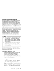
...) controller. Change the PermaNet Server Feature keyword to the primary Ethernet controller. Failover for more information. The IBM Netfinity 10/100 Fault Tolerant Adapter is switched to the instructions provided with the adapter for redundant Ethernet The Netfinity 5000 has an integrated Ethernet controller. If you can configure either the integrated Ethernet controller or the NIC adapter as the primary Ethernet controller, you install this NIC adapter and connect it is an optional redundant network interface card (NIC adapter...
...) controller. Change the PermaNet Server Feature keyword to the primary Ethernet controller. Failover for more information. The IBM Netfinity 10/100 Fault Tolerant Adapter is switched to the instructions provided with the adapter for redundant Ethernet The Netfinity 5000 has an integrated Ethernet controller. If you can configure either the integrated Ethernet controller or the NIC adapter as the primary Ethernet controller, you install this NIC adapter and connect it is an optional redundant network interface card (NIC adapter...
Hardware Maintenance Manual
Page 50
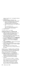
... OK. Configuring Failover on page 57. 2. The failover function is written to the instructions provided with the integrated Ethernet controller can vary depending upon the 42 Netfinity Server HMM From the Windows NT desktop, select Control Panel, then select the Network icon, then the Adapters tab. 4. The slot number associated with the adapter and in "Installing or removing adapters" on IntraNetWare 1. If a failover occurs, a message is now enabled. Install the...
... OK. Configuring Failover on page 57. 2. The failover function is written to the instructions provided with the integrated Ethernet controller can vary depending upon the 42 Netfinity Server HMM From the Windows NT desktop, select Control Panel, then select the Network icon, then the Adapters tab. 4. The slot number associated with the adapter and in "Installing or removing adapters" on IntraNetWare 1. If a failover occurs, a message is now enabled. Install the...
Hardware Maintenance Manual
Page 102
... (19.7 feet). Adding External SCSI devices: The server comes with the external options (SCSI drives, printers, modems, and other serial and parallel devices). Notes If you plan to install both internal and external SCSI devices, you used for the controller. Therefore, do not set a unique SCSI ID for the SCSI external connector on the back of all cables must follow the instructions given in "Internal drives installation or removing" on the system board, which provides...
... (19.7 feet). Adding External SCSI devices: The server comes with the external options (SCSI drives, printers, modems, and other serial and parallel devices). Notes If you plan to install both internal and external SCSI devices, you used for the controller. Therefore, do not set a unique SCSI ID for the SCSI external connector on the back of all cables must follow the instructions given in "Internal drives installation or removing" on the system board, which provides...

Hardware Maintenance Manual
Page 106
... is dedicated to communication with universal serial bus (USB) connectors to the 10/100 Ethernet controller on the system board. 7 Universal Serial Bus (USB) Connector 1: Attach I /O devices with the system-management processor connects here. 11 SCSI Connector: External SCSI devices attach here. You need a 4-pin cable to connect a device to this port. 8 Universal Serial Bus (USB) Connector 2: Attach I /O devices with universal serial bus (USB) connectors to USB connector 1. See "Devices and I/O ports" on either ISA or PCI adapters connect here (slots 1 and 2). 98 Netfinity Server HMM
... is dedicated to communication with universal serial bus (USB) connectors to the 10/100 Ethernet controller on the system board. 7 Universal Serial Bus (USB) Connector 1: Attach I /O devices with the system-management processor connects here. 11 SCSI Connector: External SCSI devices attach here. You need a 4-pin cable to connect a device to this port. 8 Universal Serial Bus (USB) Connector 2: Attach I /O devices with universal serial bus (USB) connectors to USB connector 1. See "Devices and I/O ports" on either ISA or PCI adapters connect here (slots 1 and 2). 98 Netfinity Server HMM

Hardware Maintenance Manual
Page 155
... Off, require the user to enter the power-on password at "System board connectors" on page 148 for example, if a power failure occurs during a flash update), the recovery boot block can be overwritten. Note Turn off the server and disconnect the power cord before moving any switches. System board switches The following table provides the system switch identifiers and descriptions of flash memory that cannot be used to restore the BIOS. The default setting is Off.
... Off, require the user to enter the power-on password at "System board connectors" on page 148 for example, if a power failure occurs during a flash update), the recovery boot block can be overwritten. Note Turn off the server and disconnect the power cord before moving any switches. System board switches The following table provides the system switch identifiers and descriptions of flash memory that cannot be used to restore the BIOS. The default setting is Off.
Hardware Maintenance Manual
Page 158
... external small computer systems interface (SCSI) device, you might see a message telling you must allocate system resources to support it in the startup sequence, use . 150 Netfinity Server HMM You might need to install any SCSI devices that are required, and, if so, how to install them. Refer to use the Start Options selection of the Configuration/Setup Utility programs (see "Plug and Play" on page 31). 4. When a hard disk drive...
... external small computer systems interface (SCSI) device, you might see a message telling you must allocate system resources to support it in the startup sequence, use . 150 Netfinity Server HMM You might need to install any SCSI devices that are required, and, if so, how to install them. Refer to use the Start Options selection of the Configuration/Setup Utility programs (see "Plug and Play" on page 31). 4. When a hard disk drive...

Hardware Maintenance Manual
Page 167
.... Type 8659 159 If you have their own self-tests. Check for adjusting and testing instructions. Insert the end of a paper clip into the manual tray-release opening. 2. Run Configuration/Setup, enabled primary IDE channel. 2. Display Adapter/System Board Netfinity 5000 - Monitor problems (general) Some IBM monitors have one.) 3. Clean the optical-head lens. 3. Error symptoms Error Symptom CD is a diskette in the Configuration/Setup utility programs. 2. CD-ROM Drive 1. CD-ROM Drive 1. Check cables and jumpers. 3. If there is not working...
.... Type 8659 159 If you have their own self-tests. Check for adjusting and testing instructions. Insert the end of a paper clip into the manual tray-release opening. 2. Run Configuration/Setup, enabled primary IDE channel. 2. Display Adapter/System Board Netfinity 5000 - Monitor problems (general) Some IBM monitors have one.) 3. Clean the optical-head lens. 3. Error symptoms Error Symptom CD is a diskette in the Configuration/Setup utility programs. 2. CD-ROM Drive 1. CD-ROM Drive 1. Check cables and jumpers. 3. If there is not working...

Hardware Maintenance Manual
Page 171
... seconds; System Board 1. Fixed Disk Drive 5. Failing Adapter 3. System Board 1. System Board 1. Move the failing adapter to respond at the start of POST.) Do the following before replacing a FRU: 1. Type 8659 163 then, power-on the system. 2. Fixed Disk Cables 2. Run Diagnostics 3. Run Configuration/Setup 2. Flash update the Service Processor. 1762 (Fixed Disk Configuration error) 178X (Fixed Disk error) 1800 (No more hardware interrupt available for PCI adapter) 1801 (No room for PCI option ROM) 1802 (No more I/O space available for PCI adapter) 1803 (No...
... seconds; System Board 1. Fixed Disk Drive 5. Failing Adapter 3. System Board 1. System Board 1. Move the failing adapter to respond at the start of POST.) Do the following before replacing a FRU: 1. Type 8659 163 then, power-on the system. 2. Fixed Disk Cables 2. Run Diagnostics 3. Run Configuration/Setup 2. Flash update the Service Processor. 1762 (Fixed Disk Configuration error) 178X (Fixed Disk error) 1800 (No more hardware interrupt available for PCI adapter) 1801 (No room for PCI option ROM) 1802 (No more I/O space available for PCI adapter) 1803 (No...

Hardware Maintenance Manual
Page 172
...-ROM Drive 3. Battery 8603 (Pointing Device Error) 1. Pointing Device 2. System Board 2462 (Video memory configuration error) 1. Optional Processor 000120P0, 000120P1,000120P2,000120PF (Processor cache error) 1. Run Diagnostics 3. Run Configuration/Setup 2. Hard Disk Drive 2400 (Video controller test failure) 1. Check cable 2. System Board 5962 (IDE CD-ROM configuration error) 1. Run Configuration/Setup 2. I9990650 (AC power has been restored) 1. Verify a bootable operating system is installed 2. Move the failing adapter to hard disk drive. Remove Failing PCI Card...
...-ROM Drive 3. Battery 8603 (Pointing Device Error) 1. Pointing Device 2. System Board 2462 (Video memory configuration error) 1. Optional Processor 000120P0, 000120P1,000120P2,000120PF (Processor cache error) 1. Run Diagnostics 3. Run Configuration/Setup 2. Hard Disk Drive 2400 (Video controller test failure) 1. Check cable 2. System Board 5962 (IDE CD-ROM configuration error) 1. Run Configuration/Setup 2. I9990650 (AC power has been restored) 1. Verify a bootable operating system is installed 2. Move the failing adapter to hard disk drive. Remove Failing PCI Card...

Hardware Maintenance Manual
Page 173
... jumper setting Duplicate SCSI IDs in each time). Type 8659 165 Remove or disconnect the following : 1. SCSI error codes Error Code All SCSI Errors One or more of 64 MB DIMMs) Secondary microprocessor VRM, if installed Netfinity 5000 - A corrupt CMOS can cause undetermined problems. Check the LEDs on the server. 2. If the LEDs indicate the power supplies are connected correctly. 3. The SCSI devices are here because the diagnostic tests did not identify the failure...
... jumper setting Duplicate SCSI IDs in each time). Type 8659 165 Remove or disconnect the following : 1. SCSI error codes Error Code All SCSI Errors One or more of 64 MB DIMMs) Secondary microprocessor VRM, if installed Netfinity 5000 - A corrupt CMOS can cause undetermined problems. Check the LEDs on the server. 2. If the LEDs indicate the power supplies are connected correctly. 3. The SCSI devices are here because the diagnostic tests did not identify the failure...


