
Maintenance Manual
Page 10
... Installing or Removing Drives in Bays A and B (Removable Media 69 Installing or Removing a Drive in Bay C (Diskette Drive 70 Installing or Removing Drives in Bays 1 through 5 (Hard Disk Drives 72 Changing Jumper ...Positions 75 Two-Pin Jumper Blocks 75 Completing the Installation 77 Completing the Tower Model Installation . . . . 77 Completing the Rack Model Installation . . . 80 Controls 82 Front Panel Indicators 85 DASD Fan Assembly Removal 90 Ethernet Connector 91 Expansion Bays 92 External Options 94 2 Netfinity...
... Installing or Removing Drives in Bays A and B (Removable Media 69 Installing or Removing a Drive in Bay C (Diskette Drive 70 Installing or Removing Drives in Bays 1 through 5 (Hard Disk Drives 72 Changing Jumper ...Positions 75 Two-Pin Jumper Blocks 75 Completing the Installation 77 Completing the Tower Model Installation . . . . 77 Completing the Rack Model Installation . . . 80 Controls 82 Front Panel Indicators 85 DASD Fan Assembly Removal 90 Ethernet Connector 91 Expansion Bays 92 External Options 94 2 Netfinity...

Maintenance Manual
Page 17
...your server: the system board, Ethernet controller, video controller, RAM, diskette drive, serial port, parallel port, keyboard, and mouse. Netfinity 5000 - When this occurs, work to correct the cause of passes that .... While the memory is corrected, the other error messages probably will continue. Type 8659 9 The server diagnostic test programs can cause several error messages to appear. You ... of the first error message. These numbers advance as the diskette, CD-ROM, and hard disk drives) are connected properly If you can view the interrupt request (IRQ) and direct memory ...
...your server: the system board, Ethernet controller, video controller, RAM, diskette drive, serial port, parallel port, keyboard, and mouse. Netfinity 5000 - When this occurs, work to correct the cause of passes that .... While the memory is corrected, the other error messages probably will continue. Type 8659 9 The server diagnostic test programs can cause several error messages to appear. You ... of the first error message. These numbers advance as the diskette, CD-ROM, and hard disk drives) are connected properly If you can view the interrupt request (IRQ) and direct memory ...

Maintenance Manual
Page 22
... KB of the Netfinity 5000 - Features The following table summarizes the features of level-2 cache (min) Memory Standard: 64 MB (min), expandable to 1 GB 100 MHz, error correcting code (ECC) registered synchronous dynamic random access memory (SDRAM) Four dual-inline memory-module (DIMM) sockets Diskette Drive One 3.5-inch, 1.44 MB Hard Disk Drives Up to...
... KB of the Netfinity 5000 - Features The following table summarizes the features of level-2 cache (min) Memory Standard: 64 MB (min), expandable to 1 GB 100 MHz, error correcting code (ECC) registered synchronous dynamic random access memory (SDRAM) Four dual-inline memory-module (DIMM) sockets Diskette Drive One 3.5-inch, 1.44 MB Hard Disk Drives Up to...

Maintenance Manual
Page 26
...on the number and types of hardware devices and software programs that you can also use SCSISelect to configure your server. 18 Netfinity Server HMM and change interrupt request settings; Before installing a new device or program, read the documentation that comply with the ...from among thousands of adapters and devices that comes with your server and your devices to configure your server depend on a SCSI hard disk drive. Reading the instructions helps you install in your server. The following standards: Peripheral Component Interconnect (PCI) Industry Standard Architecture (ISA...
...on the number and types of hardware devices and software programs that you can also use SCSISelect to configure your server. 18 Netfinity Server HMM and change interrupt request settings; Before installing a new device or program, read the documentation that comply with the ...from among thousands of adapters and devices that comes with your server and your devices to configure your server depend on a SCSI hard disk drive. Reading the instructions helps you install in your server. The following standards: Peripheral Component Interconnect (PCI) Industry Standard Architecture (ISA...

Maintenance Manual
Page 37
...to alert you want to run POST in the enhanced mode or in the quick mode. Type 8659 29 The value can enable the server to use a startup sequence that begins with a startable ... define a startup sequence that checks at 8 (default) Grant Timers Use this choice to disable (default) Netfinity 5000 - then, use to change values for a minimum of the core chip set on this menu, to ...this will cause grant to be set at startup for a CD-ROM, then checks an installed hard disk drive, and then checks a network adapter. Start Options: Start options take effect when you can ...
...to alert you want to run POST in the enhanced mode or in the quick mode. Type 8659 29 The value can enable the server to use a startup sequence that begins with a startable ... define a startup sequence that checks at 8 (default) Grant Timers Use this choice to disable (default) Netfinity 5000 - then, use to change values for a minimum of the core chip set on this menu, to ...this will cause grant to be set at startup for a CD-ROM, then checks an installed hard disk drive, and then checks a network adapter. Start Options: Start options take effect when you can ...
Maintenance Manual
Page 50
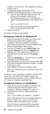
...PCNET.EXE was run), a pop-up message is located. Install the redundant NIC adapter according to your hard disk drive. The slot number associated with the adapter and in "Installing or Removing Adapters" on IntraNetWare 1. The ...failover function is located at PCI bus 0, slot 9. 7. Highlight one of the diskette created by using the following statement to the instructions provided with the integrated Ethernet controller can vary depending upon the 42 Netfinity...
...PCNET.EXE was run), a pop-up message is located. Install the redundant NIC adapter according to your hard disk drive. The slot number associated with the adapter and in "Installing or Removing Adapters" on IntraNetWare 1. The ...failover function is located at PCI bus 0, slot 9. 7. Highlight one of the diskette created by using the following statement to the instructions provided with the integrated Ethernet controller can vary depending upon the 42 Netfinity...

Maintenance Manual
Page 52
...for the location of these LEDs. There is on page 82. There is no optional processor. Action: Replace system board. 44 Netfinity Server HMM The following components: Operator LED panel For more information, see "Controls" on and operating correctly. The power outlet ... system board failed. By following the path of lights, you identify problems with some server components. Action: Replace the optional VRM. 3. Hard disk drive trays For more information, see "Power Supply LEDs." Action: Remove the optional VRM. 2. Action: Replace the system board. 4. System ...
...for the location of these LEDs. There is on page 82. There is no optional processor. Action: Replace system board. 44 Netfinity Server HMM The following components: Operator LED panel For more information, see "Controls" on and operating correctly. The power outlet ... system board failed. By following the path of lights, you identify problems with some server components. Action: Replace the optional VRM. 3. Hard disk drive trays For more information, see "Power Supply LEDs." Action: Remove the optional VRM. 2. Action: Replace the system board. 4. System ...

Maintenance Manual
Page 55
Netfinity 5000 - If the amber Hard Disk Status LED on one of the server is on, replace the hard disk drive. Type 8659 47 If the error log indicates a temperature problem and the fans are working correctly, check the system for additional information. System Error LED on the information LED panel on Description A hot-swap hard disk drive has failed. Check the error log for proper air flow. 2. The diagnostics have not detected a system error. System Board LED DASD 1 LED on the front of the hot-swap hard disk drives is off. Actions: 1.
Netfinity 5000 - If the amber Hard Disk Status LED on one of the server is on, replace the hard disk drive. Type 8659 47 If the error log indicates a temperature problem and the fans are working correctly, check the system for additional information. System Error LED on the information LED panel on Description A hot-swap hard disk drive has failed. Check the error log for proper air flow. 2. The diagnostics have not detected a system error. System Board LED DASD 1 LED on the front of the hot-swap hard disk drives is off. Actions: 1.

Maintenance Manual
Page 60
... choices. To change the device configuration Perform a low-level format or verify the media on the DASD backplane. Press Ctrl+A immediately after the IBM Netfinity Logo appears. Also, you can press the F5 key to switch between color and monochrome modes (if your server is channel A. The default ... SCSI ID already in your monitor permits). SCSI Parity Checking The default value is used by the daughterboard card (SAF-TE) on a SCSI hard disk drive. You can use the SCSISelect Utility program to: View and change the settings of 7. You can access this choice to change SCSI settings. ...
... choices. To change the device configuration Perform a low-level format or verify the media on the DASD backplane. Press Ctrl+A immediately after the IBM Netfinity Logo appears. Also, you can press the F5 key to switch between color and monochrome modes (if your server is channel A. The default ... SCSI ID already in your monitor permits). SCSI Parity Checking The default value is used by the daughterboard card (SAF-TE) on a SCSI hard disk drive. You can use the SCSISelect Utility program to: View and change the settings of 7. You can access this choice to change SCSI settings. ...

Maintenance Manual
Page 61
... include enabling support for large hard disk drives and support for advanced configuration options. To use the utility program, select a drive from the SCSISelect Utility program menu. Note If the following screen displays, you want to configure SCSI device parameters. Netfinity 5000 - Boot Device Options Select ... select SCSI Disk Utilities from the list. then, follow the instructions on the screen. No host adapter error 2h - Type 8659 53 Host Adapter SCSI Termination The default value is enabled. Unexpected SCSI Command Failure Target SCSI ID: SCSI CDB Sent: Host ...
... include enabling support for large hard disk drives and support for advanced configuration options. To use the utility program, select a drive from the SCSISelect Utility program menu. Note If the following screen displays, you want to configure SCSI device parameters. Netfinity 5000 - Boot Device Options Select ... select SCSI Disk Utilities from the list. then, follow the instructions on the screen. No host adapter error 2h - Type 8659 53 Host Adapter SCSI Termination The default value is enabled. Unexpected SCSI Command Failure Target SCSI ID: SCSI CDB Sent: Host ...

Maintenance Manual
Page 62
To install an operating system after the hard disk drive is formatted, refer to complete. 54 Netfinity Server HMM All recoverable defects will be remapped. Performing a Low-Level Disk Format: You can perform a low-level format on hard disk drives using the Format Disk feature of your files...information in the "ServerGuide and Netfinity Manager Information" section of all data and programs. 1. then, follow the instructions on the hard disk capacity, the low-level format program could take up all of the SCSISelect Utility program. Note Hard disk drives normally contain more tracks than ...
To install an operating system after the hard disk drive is formatted, refer to complete. 54 Netfinity Server HMM All recoverable defects will be remapped. Performing a Low-Level Disk Format: You can perform a low-level format on hard disk drives using the Format Disk feature of your files...information in the "ServerGuide and Netfinity Manager Information" section of all data and programs. 1. then, follow the instructions on the hard disk capacity, the low-level format program could take up all of the SCSISelect Utility program. Note Hard disk drives normally contain more tracks than ...

Maintenance Manual
Page 73
... DASD hot-swap enclosure Netfinity 5000 - A second flat-ribbon cable connects the CD-ROM drive. Another cable connects internal SCSI devices. Half height (HH) Notes: 1. A 41.3 mm drive installed in .)2 - A third connector attaches to the backplane of this cable. - It does not include hard disk drives. 2. One to the system board. Type 8659 65 A flat-ribbon signal...
... DASD hot-swap enclosure Netfinity 5000 - A second flat-ribbon cable connects the CD-ROM drive. Another cable connects internal SCSI devices. Half height (HH) Notes: 1. A 41.3 mm drive installed in .)2 - A third connector attaches to the backplane of this cable. - It does not include hard disk drives. 2. One to the system board. Type 8659 65 A flat-ribbon signal...

Maintenance Manual
Page 75
... "Termination Requirements." Netfinity 5000 - Termination Requirements: The UltraSCSI controller and the backplane of an option. Refer to perform certain preinstallation activities. Preinstallation Steps (All Bays) Before you begin, be sure you might need to the instructions that the backplane assigns for the internal SCSI bus (cable) in the hard disk drive bays or attach...
... "Termination Requirements." Netfinity 5000 - Termination Requirements: The UltraSCSI controller and the backplane of an option. Refer to perform certain preinstallation activities. Preinstallation Steps (All Bays) Before you begin, be sure you might need to the instructions that the backplane assigns for the internal SCSI bus (cable) in the hard disk drive bays or attach...

Maintenance Manual
Page 77
...8659 69 Remove the bay cover plate, if present. Remove the screws on the drive are set any switches or jumpers on either side of the server. What to do next To install a removable-media drive, go to the drive. If you want to "Installing or Removing Drives in Bays 1 through 5 (Hard Disk Drives... if necessary. For information about termination requirements, see "Termination Requirements" on page 67 1. Netfinity 5000 - To install a diskette drive, go to remove a drive, reverse the following steps. See "Option Installation" on page 174. Remove the cover plate...
...8659 69 Remove the bay cover plate, if present. Remove the screws on the drive are set any switches or jumpers on either side of the server. What to do next To install a removable-media drive, go to the drive. If you want to "Installing or Removing Drives in Bays 1 through 5 (Hard Disk Drives... if necessary. For information about termination requirements, see "Termination Requirements" on page 67 1. Netfinity 5000 - To install a diskette drive, go to remove a drive, reverse the following steps. See "Option Installation" on page 174. Remove the cover plate...

Maintenance Manual
Page 80
...-swap bays connect to install must have a hot-swap-drive tray attached. Installing or Removing Drives in the rack before installing the hard disk drives. Before you begin Read "Safety Information" on page 67 Your Netfinity 5000 contains hardware that you replace a hard disk drive without turning off the Netfinity 5000. These drives are known as hot-swappable or hot-swap...
...-swap bays connect to install must have a hot-swap-drive tray attached. Installing or Removing Drives in the rack before installing the hard disk drives. Before you begin Read "Safety Information" on page 67 Your Netfinity 5000 contains hardware that you replace a hard disk drive without turning off the Netfinity 5000. These drives are known as hot-swappable or hot-swap...

Maintenance Manual
Page 81
.... Type 8659 73 b. Notes 1. consult the documentation that it away from one of the empty hot-swap bays by inserting your disk arrays after installing hard disk drives; To install a drive in the hot-swap bay. Align the drive-tray assembly so that came with your Netfinity 5000 has a... RAID adapter or controller, you might want to the backplane. a. Netfinity 5000 - c. Remove the filler panel 1 from...
.... Type 8659 73 b. Notes 1. consult the documentation that it away from one of the empty hot-swap bays by inserting your disk arrays after installing hard disk drives; To install a drive in the hot-swap bay. Align the drive-tray assembly so that came with your Netfinity 5000 has a... RAID adapter or controller, you might want to the backplane. a. Netfinity 5000 - c. Remove the filler panel 1 from...

Maintenance Manual
Page 83
Two-Pin Jumper Blocks: Covering both pins with one pin only or removing the jumper entirely changes the function of the SCSI hard disk drive hot-swap bays. Locate the jumper block, removing any adapters or components that pin only. Covering one of the pins on the pin block...to the jumper block. 4. Type 8659 75 then disconnect the server power cord. 2. Do one of the following: Remove a jumper by aligning the holes in the bottom of the jumper with a jumper specifies one of the holes in the bottom of the jumper block. Netfinity 5000 - Changing Jumper Positions The DASD ...
Two-Pin Jumper Blocks: Covering both pins with one pin only or removing the jumper entirely changes the function of the SCSI hard disk drive hot-swap bays. Locate the jumper block, removing any adapters or components that pin only. Covering one of the pins on the pin block...to the jumper block. 4. Type 8659 75 then disconnect the server power cord. 2. Do one of the following: Remove a jumper by aligning the holes in the bottom of the jumper with a jumper specifies one of the holes in the bottom of the jumper block. Netfinity 5000 - Changing Jumper Positions The DASD ...

Maintenance Manual
Page 91
... Switch from the CD-ROM drive. The server also might damage the information stored on a hard disk drive or on . Do not set the server to the Standby mode if any drive in-use light is on ... to release the left-side cover. 8 CD-ROM Drive In-Use Light: This light comes on when the CD-ROM drive is accessed. Type 8659 83 Important After you plug the server power cord into...To remove all electrical current from the power source. This might have more than one power cord. Netfinity 5000 - To toggle the server between Standby mode and actively running, press and release the Power-On ...
... Switch from the CD-ROM drive. The server also might damage the information stored on a hard disk drive or on . Do not set the server to the Standby mode if any drive in-use light is on ... to release the left-side cover. 8 CD-ROM Drive In-Use Light: This light comes on when the CD-ROM drive is accessed. Type 8659 83 Important After you plug the server power cord into...To remove all electrical current from the power source. This might have more than one power cord. Netfinity 5000 - To toggle the server between Standby mode and actively running, press and release the Power-On ...

Maintenance Manual
Page 94
...errors can include high temperature, excess current, or failure or errors in the microprocessor, system fan, memory, PCI bus, SCSI bus, USB, hard disk drive, diskette drive, serial port, keyboard interface, or power supply. When this light is not on, the power cord is not connected or the power supply ...Standby mode (power is present but the server is reserved for future use. 86 Netfinity Server HMM If this LED is on, one or more LEDs on self-test (POST) without any errors. 3 SCSI Hard Disk Drive In-Use Light: This green LED lights when your server remotely (Unattended mode) ...
...errors can include high temperature, excess current, or failure or errors in the microprocessor, system fan, memory, PCI bus, SCSI bus, USB, hard disk drive, diskette drive, serial port, keyboard interface, or power supply. When this light is not on, the power cord is not connected or the power supply ...Standby mode (power is present but the server is reserved for future use. 86 Netfinity Server HMM If this LED is on, one or more LEDs on self-test (POST) without any errors. 3 SCSI Hard Disk Drive In-Use Light: This green LED lights when your server remotely (Unattended mode) ...

Maintenance Manual
Page 95
Netfinity 5000 - If you do not have a RAID environment, this amber LED lights continuously when the drive is 100 Mbps. You can replace these hot-swappable drives without turning off the server. Type 8659 87 8 Hard Disk Drive Status Light (Amber): In a RAID environment, this LED is not operational. 9 Hard Disk Drive Activity Light (Green): This green LED lights when...
Netfinity 5000 - If you do not have a RAID environment, this amber LED lights continuously when the drive is 100 Mbps. You can replace these hot-swappable drives without turning off the server. Type 8659 87 8 Hard Disk Drive Status Light (Amber): In a RAID environment, this LED is not operational. 9 Hard Disk Drive Activity Light (Green): This green LED lights when...


