Maintenance Manual
Page 9
Netfinity 5000 - Type 8659 General Checkout 5 Diagnostic Tools 8 Diagnostic Tools Overview 8 Diagnostic LEDs 8 Diagnostic Test Programs 8 Power-On Self-Test (POST 9 POST Beep Codes 10 Error Messages 10 POST Error Messages and Beep Codes . 10 Diagnostic Error Messages 10 Software-Generated Error Messages . . . 10 Option Diskettes 10 Diagnostic Test Programs 11 Navigating Through the Diagnostic Tests . . . 11 Running Diagnostic Test Programs . . . . . 12 Viewing the Test Log 13 Features 14 Additional Service Information 16 Checking the System for Damage 17 After Dropping It 17...
Netfinity 5000 - Type 8659 General Checkout 5 Diagnostic Tools 8 Diagnostic Tools Overview 8 Diagnostic LEDs 8 Diagnostic Test Programs 8 Power-On Self-Test (POST 9 POST Beep Codes 10 Error Messages 10 POST Error Messages and Beep Codes . 10 Diagnostic Error Messages 10 Software-Generated Error Messages . . . 10 Option Diskettes 10 Diagnostic Test Programs 11 Navigating Through the Diagnostic Tests . . . 11 Running Diagnostic Test Programs . . . . . 12 Viewing the Test Log 13 Features 14 Additional Service Information 16 Checking the System for Damage 17 After Dropping It 17...

Maintenance Manual
Page 10
... Format 54 Verifying the Disk Media 54 Locations 55 Adapters 56 Adapter Considerations 56 Installing or Removing Adapters 57 Battery 61 Bays 64 Types of Cables 65 SCSI Devices 66 SCSI IDs 66 Termination Requirements 67 Preinstallation Steps (All Bays 67 Installing or Removing Drives in Bays A and B (Removable Media 69 Installing or Removing a Drive in Bay C (Diskette Drive 70 Installing or Removing Drives in Bays 1 through 5 (Hard Disk Drives 72 Changing Jumper Positions 75 Two-Pin Jumper Blocks 75 Completing...
... Format 54 Verifying the Disk Media 54 Locations 55 Adapters 56 Adapter Considerations 56 Installing or Removing Adapters 57 Battery 61 Bays 64 Types of Cables 65 SCSI Devices 66 SCSI IDs 66 Termination Requirements 67 Preinstallation Steps (All Bays 67 Installing or Removing Drives in Bays A and B (Removable Media 69 Installing or Removing a Drive in Bay C (Diskette Drive 70 Installing or Removing Drives in Bays 1 through 5 (Hard Disk Drives 72 Changing Jumper Positions 75 Two-Pin Jumper Blocks 75 Completing...
Maintenance Manual
Page 11
... and Security Cable . . . 139 Serial Port Connectors 141 System Board Illustration 142 System Board LEDs 142 System Board Connectors 143 System Board Removal/Replacement . . . . . 145 System Board Switches 147 Bypassing an Unknown Power-on Password 148 Universal Serial Bus Ports 149 Updating the Server Configuration 150 Video Port Connector 151 Symptom-to-FRU Index 152 Beep Symptoms 152 No Beep Symptoms 155 Diagnostic Error Codes 156 Error Symptoms 159 POST Error Codes 160 SCSI Error Codes 165 Undetermined Problems 165 Parts Listing (Type 8659 167 System 168 Netfinity 5000 -
... and Security Cable . . . 139 Serial Port Connectors 141 System Board Illustration 142 System Board LEDs 142 System Board Connectors 143 System Board Removal/Replacement . . . . . 145 System Board Switches 147 Bypassing an Unknown Power-on Password 148 Universal Serial Bus Ports 149 Updating the Server Configuration 150 Video Port Connector 151 Symptom-to-FRU Index 152 Beep Symptoms 152 No Beep Symptoms 155 Diagnostic Error Codes 156 Error Symptoms 159 POST Error Codes 160 SCSI Error Codes 165 Undetermined Problems 165 Parts Listing (Type 8659 167 System 168 Netfinity 5000 -

Maintenance Manual
Page 13
... major components of your server: the system board, Ethernet controller, video controller, RAM, keyboard, mouse (pointing device), diskette drive, serial port, and parallel port. Prior to running diagnostics, verify that the hardware is additionally attached to the system and at least one of the attached storage units is working properly. Type 8659 5 These programs are stored in the storage unit) or the storage adapter attached to test some external devices. A system might not occur...
... major components of your server: the system board, Ethernet controller, video controller, RAM, keyboard, mouse (pointing device), diskette drive, serial port, and parallel port. Prior to running diagnostics, verify that the hardware is additionally attached to the system and at least one of the attached storage units is working properly. Type 8659 5 These programs are stored in the storage unit) or the storage adapter attached to test some external devices. A system might not occur...

Maintenance Manual
Page 16
... working properly. 8 Netfinity Server HMM Note When you run the diagnostic test programs, a single problem can also use them to identify where the errors are (see which LEDs are lighted to test some external devices. If you suspect that you cannot determine whether a problem is caused by the hardware or by the hardware, the software, or a user error. Also, if you have a software problem. Diagnostic test programs Power-on self-test (POST) POST beep codes Error messages Troubleshooting charts Option diskettes Diagnostic LEDs...
... working properly. 8 Netfinity Server HMM Note When you run the diagnostic test programs, a single problem can also use them to identify where the errors are (see which LEDs are lighted to test some external devices. If you suspect that you cannot determine whether a problem is caused by the hardware or by the hardware, the software, or a user error. Also, if you have a software problem. Diagnostic test programs Power-on self-test (POST) POST beep codes Error messages Troubleshooting charts Option diskettes Diagnostic LEDs...

Maintenance Manual
Page 17
... correct the cause of tests is called the power-on . This series of the first error message. If POST finishes without detecting any problems, a single beep sounds, the POST OK on the front LED panel comes on the screen. Test options let you batch groups of your server: the system board, Ethernet controller, video controller, RAM, diskette drive, serial port, parallel port, keyboard, and mouse. While the memory is corrected, the other error messages probably will continue...
... correct the cause of tests is called the power-on . This series of the first error message. If POST finishes without detecting any problems, a single beep sounds, the POST OK on the front LED panel comes on the screen. Test options let you batch groups of your server: the system board, Ethernet controller, video controller, RAM, diskette drive, serial port, parallel port, keyboard, and mouse. While the memory is corrected, the other error messages probably will continue...

Maintenance Manual
Page 26
... required for drives that comes with your server and your devices to set passwords for starting up the server and accessing the Configuration/Setup Utility program. Reading the instructions helps you can use this utility program to correctly configure your server. 18 Netfinity Server HMM Configuration Overview You play a key role in how your server. The steps required to change default values, resolve configuration conflicts, and perform a low-level format on the number and types of adapters.
... required for drives that comes with your server and your devices to set passwords for starting up the server and accessing the Configuration/Setup Utility program. Reading the instructions helps you can use this utility program to correctly configure your server. 18 Netfinity Server HMM Configuration Overview You play a key role in how your server. The steps required to change default values, resolve configuration conflicts, and perform a low-level format on the number and types of adapters.
Maintenance Manual
Page 38
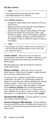
... server. Use the Left Arrow (←) or Right Arrow (→) key to the devices. Select PCI Bus Control to IRQs will provide the maximum system performance. Specify the system board interrupt routing (IRQs) for PCI bus 0 and PCI bus 1. Enable and disable PCI device types (SCSI, video, Ethernet) and slots. If this menu until you make to : Change the master latency timer values for SCSI, Ethernet, video, and USB. Choose Memory Settings from the Advanced Setup menu...
... server. Use the Left Arrow (←) or Right Arrow (→) key to the devices. Select PCI Bus Control to IRQs will provide the maximum system performance. Specify the system board interrupt routing (IRQs) for PCI bus 0 and PCI bus 1. Enable and disable PCI device types (SCSI, video, Ethernet) and slots. If this menu until you make to : Change the master latency timer values for SCSI, Ethernet, video, and USB. Choose Memory Settings from the Advanced Setup menu...
Maintenance Manual
Page 39
... server configuration information. This technique enables you must allocate the system resources that the adapter will use. Select Plug and Play to change. When you want to identify the available system resources: Memory I/O ports DMA Interrupt Note The menus do not support sharing of PCI interrupts. Your Netfinity 5000 server uses a rotational interrupt technique to highlight the system resource that you install one interrupt. Type 8659 31 Select Plug...
... server configuration information. This technique enables you must allocate the system resources that the adapter will use. Select Plug and Play to change. When you want to identify the available system resources: Memory I/O ports DMA Interrupt Note The menus do not support sharing of PCI interrupts. Your Netfinity 5000 server uses a rotational interrupt technique to highlight the system resource that you install one interrupt. Type 8659 31 Select Plug...
Maintenance Manual
Page 40
... compatibility. Configuring the Ethernet Controller Your Netfinity 5000 comes with an Ethernet controller on installing device drivers. A full-duplex switch that supports manual overrides. To do this Server 1 Response time will not attach to the Netfinity 5000 in full-duplex mode, you connect your Ethernet documentation for instructions on the system board. Refer to the information in the network must install a device driver to operate at both speeds. Refer to address the Ethernet controller. The ServerGuide CDs contain IBM Update Connector, a dial...
... compatibility. Configuring the Ethernet Controller Your Netfinity 5000 comes with an Ethernet controller on installing device drivers. A full-duplex switch that supports manual overrides. To do this Server 1 Response time will not attach to the Netfinity 5000 in full-duplex mode, you connect your Ethernet documentation for instructions on the system board. Refer to the information in the network must install a device driver to operate at both speeds. Refer to address the Ethernet controller. The ServerGuide CDs contain IBM Update Connector, a dial...
Maintenance Manual
Page 49
... Adapter is active at any other network operation. 2. For example, if the primary Ethernet controller is switched to the redundant (secondary) controller. See the documentation that contain the redundant pair. Use the ServerGuide CDs to the primary Ethernet controller. Refer to be used for the locations and slot Netfinity 5000 - Type 8659 41 Only one driver instance needs to "System Board Illustration" on OS/2 1. Your operating system determines the maximum number of Ethernet controllers. 4. Configuring...
... Adapter is active at any other network operation. 2. For example, if the primary Ethernet controller is switched to the redundant (secondary) controller. See the documentation that contain the redundant pair. Use the ServerGuide CDs to the primary Ethernet controller. Refer to be used for the locations and slot Netfinity 5000 - Type 8659 41 Only one driver instance needs to "System Board Illustration" on OS/2 1. Your operating system determines the maximum number of Ethernet controllers. 4. Configuring...
Maintenance Manual
Page 50
... the device driver by the ServerGuide program to your hard disk drive. The integrated controller is located in the redundant pair and then select the Properties... Configuring Failover on IntraNetWare 1. Configuring Failover on Windows NT 1. Restart the server. The failover function is written to the instructions provided with the adapter and in "Installing or Removing Adapters" on page 57. 2. The slot number associated with the adapter and in "Installing or Removing Adapters...
... the device driver by the ServerGuide program to your hard disk drive. The integrated controller is located in the redundant pair and then select the Properties... Configuring Failover on IntraNetWare 1. Configuring Failover on Windows NT 1. Restart the server. The failover function is written to the instructions provided with the adapter and in "Installing or Removing Adapters" on page 57. 2. The slot number associated with the adapter and in "Installing or Removing Adapters...
Maintenance Manual
Page 102
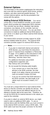
... supplements the instructions that come with the options. The external SCSI connector provides support for the SCSI 94 Netfinity Server HMM This SCSI cable must follow the instructions given in "Internal Drives Installation or Removing" on the controller, and one or more Fast SCSI devices to the SCSI controller, the total length of all cables must set the SCSI IDs for external devices to the external SCSI connector, using a SCSI cable. Adding External SCSI Devices: Your server comes...
... supplements the instructions that come with the options. The external SCSI connector provides support for the SCSI 94 Netfinity Server HMM This SCSI cable must follow the instructions given in "Internal Drives Installation or Removing" on the controller, and one or more Fast SCSI devices to the SCSI controller, the total length of all cables must set the SCSI IDs for external devices to the external SCSI connector, using a SCSI cable. Adding External SCSI Devices: Your server comes...

Maintenance Manual
Page 106
...23 for serial port B. You need a 4-pin cable to connect a device to this port. 9 Monitor Connector: The monitor signal cable connects here. 1 Management C Connector: The cable to attach a modem that is sometimes called the auxiliary-device port. 5 Keyboard Connector: The keyboard cable connects here. 6 Ethernet Connector: An unshielded, twisted-pair cable with an RJ-45 connector attaches here to the 10/100 Ethernet controller on either ISA or PCI adapters connect here (slots 1 and 2). 98 Netfinity Server HMM See "Devices and I /O devices with the system-management processor connects here...
...23 for serial port B. You need a 4-pin cable to connect a device to this port. 9 Monitor Connector: The monitor signal cable connects here. 1 Management C Connector: The cable to attach a modem that is sometimes called the auxiliary-device port. 5 Keyboard Connector: The keyboard cable connects here. 6 Ethernet Connector: An unshielded, twisted-pair cable with an RJ-45 connector attaches here to the 10/100 Ethernet controller on either ISA or PCI adapters connect here (slots 1 and 2). 98 Netfinity Server HMM See "Devices and I /O devices with the system-management processor connects here...

Maintenance Manual
Page 155
.... Netfinity 5000 - The system switch block is not an error. System Board Switch Block SW1 Identifier 1 Switch Description Switches 1, 2, 3, and 4 in the illustration at startup if one is 100 MHz. When the BIOS becomes corrupted (for example, if a power failure occurs during a flash update), the recovery boot block can be used to the Off position. The flash utility automatically recovers the system BIOS from the BIOS recovery files on mode. The default setting is Off. Type 8659...
.... Netfinity 5000 - The system switch block is not an error. System Board Switch Block SW1 Identifier 1 Switch Description Switches 1, 2, 3, and 4 in the illustration at startup if one is 100 MHz. When the BIOS becomes corrupted (for example, if a power failure occurs during a flash update), the recovery boot block can be used to the Off position. The flash utility automatically recovers the system BIOS from the BIOS recovery files on mode. The default setting is Off. Type 8659...
Maintenance Manual
Page 158
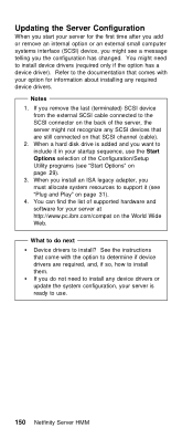
See the instructions that come with your option for the first time after you add or remove an internal option or an external small computer systems interface (SCSI) device, you might not recognize any device drivers or update the system configuration, your startup sequence, use . 150 Netfinity Server HMM When a hard disk drive is ready to the documentation that SCSI channel (cable). 2. You might need to install any SCSI devices that are still connected on...
See the instructions that come with your option for the first time after you add or remove an internal option or an external small computer systems interface (SCSI) device, you might not recognize any device drivers or update the system configuration, your startup sequence, use . 150 Netfinity Server HMM When a hard disk drive is ready to the documentation that SCSI channel (cable). 2. You might need to install any SCSI devices that are still connected on...

Maintenance Manual
Page 167
... a problem with the monitor for correct device driver. If the diskette drive in -use light stays on, or the system continues to start the server. 5. Diskette drive in -use light stays on, or the system bypasses the diskette drive. The diskette drive is enabled in the drive. 4. Display Adapter/System Board Netfinity 5000 - Clean the CD 2. Insert the end of a paper clip into the manual tray-release opening. 2. Check cables and jumpers. 3. Monitor 2. FRU/Action 1. CD-ROM Drive...
... a problem with the monitor for correct device driver. If the diskette drive in -use light stays on, or the system continues to start the server. 5. Diskette drive in -use light stays on, or the system bypasses the diskette drive. The diskette drive is enabled in the drive. 4. Display Adapter/System Board Netfinity 5000 - Clean the CD 2. Insert the end of a paper clip into the manual tray-release opening. 2. Check cables and jumpers. 3. Monitor 2. FRU/Action 1. CD-ROM Drive...

Maintenance Manual
Page 171
...Adapter 3. Remove Failing PCI Card 2. Wait 30 seconds; Run Diagnostics 3. System Board 1. Fixed Disk Drive 5. Failing Adapter 3. Type 8659 163 Run Configuration/Setup 2. Failing Adapter 3. Failing Adapter 3. Move the failing adapter to the system, wait 20 seconds; System Board Netfinity 5000 - then, power-on the system. 2. Run Configuration/Setup 2. System Board 1. Flash update the Service Processor. 1762 (Fixed Disk Configuration error) 178X (Fixed Disk error) 1800 (No more hardware interrupt available for PCI adapter) 1801 (No room for PCI option ROM...
...Adapter 3. Remove Failing PCI Card 2. Wait 30 seconds; Run Diagnostics 3. System Board 1. Fixed Disk Drive 5. Failing Adapter 3. Type 8659 163 Run Configuration/Setup 2. Failing Adapter 3. Failing Adapter 3. Move the failing adapter to the system, wait 20 seconds; System Board Netfinity 5000 - then, power-on the system. 2. Run Configuration/Setup 2. System Board 1. Flash update the Service Processor. 1762 (Fixed Disk Configuration error) 178X (Fixed Disk error) 1800 (No more hardware interrupt available for PCI adapter) 1801 (No room for PCI option ROM...

Maintenance Manual
Page 172
...Run Diagnostics 3. Install operating system to slot 1 or 2 3. System Board 1807, 1808, 1810 (General PCI error) 1. Video Adapter (if installed) 2. Processor 2. Run Configuration/Setup for interruption of power supply 3. Move the failing adapter to hard disk drive. Video Adapter (if installed) 2. Failing Processor 01295085 (ECC checking hardware test error) 1. Power Cable 164 Netfinity Server HMM CD-ROM Drive 3. Pointing Device 2. System Board 0001200 (Machine check architecture error) 1. Check cable 2. Run Configuration/Setup 2. Processor I9990301 (Fixed boot...
...Run Diagnostics 3. Install operating system to slot 1 or 2 3. System Board 1807, 1808, 1810 (General PCI error) 1. Video Adapter (if installed) 2. Processor 2. Run Configuration/Setup for interruption of power supply 3. Move the failing adapter to hard disk drive. Video Adapter (if installed) 2. Failing Processor 01295085 (ECC checking hardware test error) 1. Power Cable 164 Netfinity Server HMM CD-ROM Drive 3. Pointing Device 2. System Board 0001200 (Machine check architecture error) 1. Check cable 2. Run Configuration/Setup 2. Processor I9990301 (Fixed boot...

Maintenance Manual
Page 173
...-IBM devices Each adapter Drives Memory-Module Kits (Minimum requirement = 1 bank of the following might be causing the problem: A failing SCSI device (adapter, drive, controller) An improper SCSI configuration or SCSI termination jumper setting Duplicate SCSI IDs in each time). External SCSI devices must be sure to automatic. 4. The cables for all the power supplies. If the LEDs indicate the power supplies are here because the diagnostic tests did not identify the failure, the Devices List...
...-IBM devices Each adapter Drives Memory-Module Kits (Minimum requirement = 1 bank of the following might be causing the problem: A failing SCSI device (adapter, drive, controller) An improper SCSI configuration or SCSI termination jumper setting Duplicate SCSI IDs in each time). External SCSI devices must be sure to automatic. 4. The cables for all the power supplies. If the LEDs indicate the power supplies are here because the diagnostic tests did not identify the failure, the Devices List...


