
Hardware Maintenance Manual
Page 6
... or forgotten password (clearing CMOS Flash update procedures Updating (flashing) BIOS from a diskette or CD-ROM Updating (flashing) BIOS from your comments 280 Problem determination tips 281 Notices 281 Trademarks 282 iv Hardware Maintenance Manual Parts listing 119 Type 8128 119 Type 8185 121 Type 8186 130 Type 8187 134 Type 8188 149 Type 8189 158...
... or forgotten password (clearing CMOS Flash update procedures Updating (flashing) BIOS from a diskette or CD-ROM Updating (flashing) BIOS from your comments 280 Problem determination tips 281 Notices 281 Trademarks 282 iv Hardware Maintenance Manual Parts listing 119 Type 8128 119 Type 8185 121 Type 8186 130 Type 8187 134 Type 8188 149 Type 8189 158...
Hardware Maintenance Manual
Page 70
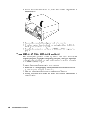
...installed, you might impede the replacement of the cover. 3. Types 8128, 8187, 8188, 8193, 8414, and 8431 After replacing FRUs, you must update (flash) the BIOS. To update the configuration, see Chapter 5, "IBM Setup Utility program," on the option that no tools or loose screws are... left inside the computer. 2. See "Flash update procedures" on page 113. 6. 3. To replace the ...
...installed, you might impede the replacement of the cover. 3. Types 8128, 8187, 8188, 8193, 8414, and 8431 After replacing FRUs, you must update (flash) the BIOS. To update the configuration, see Chapter 5, "IBM Setup Utility program," on the option that no tools or loose screws are... left inside the computer. 2. See "Flash update procedures" on page 113. 6. 3. To replace the ...

Hardware Maintenance Manual
Page 71
...and reconnect any cables that is installed, you must update (flash) the BIOS. Chapter 6. 4. Also, depending on the bottom of the cover. 3. To replace the cover and connect cables to confirm the updated information in the IBM Setup Utility program. To update the configuration, see Chapter 5, "IBM Setup Utility program," on page 113. 6. Ensure .... If you have been reassembled correctly and that the rail guides on the option that might need to the computer. 5. See "Flash update procedures" on page 19. Clear any cables, including telephone lines and power cords.
...and reconnect any cables that is installed, you must update (flash) the BIOS. Chapter 6. 4. Also, depending on the bottom of the cover. 3. To replace the cover and connect cables to confirm the updated information in the IBM Setup Utility program. To update the configuration, see Chapter 5, "IBM Setup Utility program," on page 113. 6. Ensure .... If you have been reassembled correctly and that the rail guides on the option that might need to the computer. 5. See "Flash update procedures" on page 19. Clear any cables, including telephone lines and power cords.

Hardware Maintenance Manual
Page 72
4. To update the configuration, see Chapter 5, "IBM Setup Utility program," on page 113. 6. Position the cover on the chassis so that the guides on the top and... replacement of the cover engage the chassis and push the cover to confirm the updated information in the IBM Setup Utility program. Types 8196 and 8197 After replacing FRUs, you must update (flash) the BIOS. To replace the cover and connect cables to the computer. 5. Clear any ... for a few seconds and then turn on the option that secure the cover. 66 Hardware Maintenance Manual See "Flash update procedures" on page 19.
4. To update the configuration, see Chapter 5, "IBM Setup Utility program," on page 113. 6. Position the cover on the chassis so that the guides on the top and... replacement of the cover engage the chassis and push the cover to confirm the updated information in the IBM Setup Utility program. Types 8196 and 8197 After replacing FRUs, you must update (flash) the BIOS. To replace the cover and connect cables to the computer. 5. Clear any ... for a few seconds and then turn on the option that secure the cover. 66 Hardware Maintenance Manual See "Flash update procedures" on page 19.

Hardware Maintenance Manual
Page 73
See "Flash update procedures" on page 19. Reconnect the external cables and power cords to turn on for a few seconds and then turn off. To update the configuration, see Chapter 5, "IBM Setup Utility program," on page 113. 6. Chapter 6. If you have replaced the system board, you must update (flash) the BIOS. Note: When the power cord is a normal sequence to enable the computer to initialize. This is first plugged in, the computer might appear to the computer. 5. Replacing FRUs 67 4.
See "Flash update procedures" on page 19. Reconnect the external cables and power cords to turn on for a few seconds and then turn off. To update the configuration, see Chapter 5, "IBM Setup Utility program," on page 113. 6. Chapter 6. If you have replaced the system board, you must update (flash) the BIOS. Note: When the power cord is a normal sequence to enable the computer to initialize. This is first plugged in, the computer might appear to the computer. 5. Replacing FRUs 67 4.

Hardware Maintenance Manual
Page 99
... board System Board 1. Run Setup and verify Configuration 2. CMOS Backup Battery. Time and Date Set 2. Run Setup. See "Recovering from a POST/BIOS update failure" on page 19.) 2. Riser card 1. Fan 2. Go to "Replacing the battery (all machine types)" on page 56 3. Run the Extended... on page 56 5. Run Setup 2. CMOS Backup Battery. CMOS Backup Battery. Check System Summary menu for memory size change. (See Chapter 5, "IBM Setup Utility program," on page 114. 2. System Board Chapter 7. If not, suspect that device. 3. Run Flash Recovery using Boot Block. Any...
... board System Board 1. Run Setup and verify Configuration 2. CMOS Backup Battery. Time and Date Set 2. Run Setup. See "Recovering from a POST/BIOS update failure" on page 19.) 2. Riser card 1. Fan 2. Go to "Replacing the battery (all machine types)" on page 56 3. Run the Extended... on page 56 5. Run Setup 2. CMOS Backup Battery. CMOS Backup Battery. Check System Summary menu for memory size change. (See Chapter 5, "IBM Setup Utility program," on page 114. 2. System Board Chapter 7. If not, suspect that device. 3. Run Flash Recovery using Boot Block. Any...

Hardware Maintenance Manual
Page 100
POST Error Code 167 No Processor BIOS Update Found 168 Alert on LAN are enabled in the IBM Setup Utility program. 2. Check to access the computer System Board System Board System Board System Board System Board System Board System Board 94 Hardware ... Reset 193 System Security: IBM Embedded Security Hardware Removed 194 System Security: Asset ID Antenna has been Removed 195 System Security: Asset ID Antenna has been Installed 196 System Tampered Cleared 1XX Not listed above FRU/Action 1. Check Stepping level for the BIOS level needed, then perform the flash update. 2. System Board 1....
POST Error Code 167 No Processor BIOS Update Found 168 Alert on LAN are enabled in the IBM Setup Utility program. 2. Check to access the computer System Board System Board System Board System Board System Board System Board System Board 94 Hardware ... Reset 193 System Security: IBM Embedded Security Hardware Removed 194 System Security: Asset ID Antenna has been Removed 195 System Security: Asset ID Antenna has been Installed 196 System Tampered Cleared 1XX Not listed above FRU/Action 1. Check Stepping level for the BIOS level needed, then perform the flash update. 2. System Board 1....

Hardware Maintenance Manual
Page 118
... computer, and where to determine the level of BIOS. To update the VPD, see "Flash update procedures" on page 113. 112 Hardware Maintenance Manual Run the IBM Setup Utility program to obtain the latest level of BIOS installed. IBM Support Center 4. RETAIN® v Sources for determining the latest level BIOS available 1. If the administrator password is lost...
... computer, and where to determine the level of BIOS. To update the VPD, see "Flash update procedures" on page 113. 112 Hardware Maintenance Manual Run the IBM Setup Utility program to obtain the latest level of BIOS installed. IBM Support Center 4. RETAIN® v Sources for determining the latest level BIOS available 1. If the administrator password is lost...

Hardware Maintenance Manual
Page 119
... 4 on page 38 for your machine type and click Go. 4. Move the jumper back to flash (update) the BIOS. Updating (flashing) BIOS from the standard position (pins 1 and 2) to the IBM Web site, Web page content (including the links referenced in the address field and press Enter. 2. Additional...6. The computer will turn off the computer by date, click your browser, type http://www.ibm.com/pc/support// in the following procedure) is stored in the EEPROM on page 63. 7. Updating (flashing) BIOS from your desktop. In these models, the password is subject to change. 1. Turn off ....
... 4 on page 38 for your machine type and click Go. 4. Move the jumper back to flash (update) the BIOS. Updating (flashing) BIOS from the standard position (pins 1 and 2) to the IBM Web site, Web page content (including the links referenced in the address field and press Enter. 2. Additional...6. The computer will turn off the computer by date, click your browser, type http://www.ibm.com/pc/support// in the following procedure) is stored in the EEPROM on page 63. 7. Updating (flashing) BIOS from your desktop. In these models, the password is subject to change. 1. Turn off ....
Hardware Maintenance Manual
Page 120
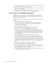
... recovery jumper to continue. 14. Restore power to the system and power the system on page 25 or the label inside the computer for Flash BIOS update from the list and press Enter. 11. Connect the power cord back to the system by a single long beep and then silence from the...diskette from the system speaker. Return the boot block recovery jumper to turn the system off the computer and remove the cover. 2. The standard POST/BIOS Update Utility screen will report several POST errors. These errors can be left in the floppy disk drive. 5. When the system POST tests, it will ...
... recovery jumper to continue. 14. Restore power to the system and power the system on page 25 or the label inside the computer for Flash BIOS update from the list and press Enter. 11. Connect the power cord back to the system by a single long beep and then silence from the...diskette from the system speaker. Return the boot block recovery jumper to turn the system off the computer and remove the cover. 2. The standard POST/BIOS Update Utility screen will report several POST errors. These errors can be left in the floppy disk drive. 5. When the system POST tests, it will ...


