
Hardware Maintenance Manual
Page 5
... 19 Starting the IBM Setup Utility program . . . . . 19 Viewing and changing settings 19 Exiting from the IBM Setup Utility program . . . 20 Using passwords 20 User password 20 Administrator password 20 Setting, changing, and deleting a password . . . 20 Using Security Profile by Device 21 Using IDE Drives Setup 21 Selecting a startup device 22 Selecting a temporary startup device . . . . . 22 Changing the startup device sequence . . . . 22 Chapter 6. Replacing FRUs 23 Locating connectors on the front 23 Types 8185, 8186, 8192, 8413, and 8430 . . . . 23 Types 8128, 8187, 8188...
... 19 Starting the IBM Setup Utility program . . . . . 19 Viewing and changing settings 19 Exiting from the IBM Setup Utility program . . . 20 Using passwords 20 User password 20 Administrator password 20 Setting, changing, and deleting a password . . . 20 Using Security Profile by Device 21 Using IDE Drives Setup 21 Selecting a startup device 22 Selecting a temporary startup device . . . . . 22 Changing the startup device sequence . . . . 22 Chapter 6. Replacing FRUs 23 Locating connectors on the front 23 Types 8185, 8186, 8192, 8413, and 8430 . . . . 23 Types 8128, 8187, 8188...

Hardware Maintenance Manual
Page 6
... Passwords Vital product data BIOS levels Erasing a lost or forgotten password (clearing CMOS Flash update procedures Updating (flashing) BIOS from a diskette or CD-ROM Updating (flashing) BIOS from your comments 280 Problem determination tips 281 Notices 281 Trademarks 282 iv Hardware Maintenance Manual Parts listing 119 Type 8128 119 Type 8185 121 Type 8186 130 Type 8187 134 Type 8188 149 Type 8189 158 Type 8190 Type 8192 Type 8193 Type 8194 Type 8195 Type 8196 Type 8197 Type 8413 Type 8414 Type 8415 Type 8430 Type 8431 Type 8432 Type...
... Passwords Vital product data BIOS levels Erasing a lost or forgotten password (clearing CMOS Flash update procedures Updating (flashing) BIOS from a diskette or CD-ROM Updating (flashing) BIOS from your comments 280 Problem determination tips 281 Notices 281 Trademarks 282 iv Hardware Maintenance Manual Parts listing 119 Type 8128 119 Type 8185 121 Type 8186 130 Type 8187 134 Type 8188 149 Type 8189 158 Type 8190 Type 8192 Type 8193 Type 8194 Type 8195 Type 8196 Type 8197 Type 8413 Type 8414 Type 8415 Type 8430 Type 8431 Type 8432 Type...
Hardware Maintenance Manual
Page 9
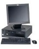
...Support for four dual inline memory modules (DIMMs) v 512 KB flash memory for system programs Internal drives v 3.5-inch, 1.44 MB diskette drive v Internal hard disk drive v EIDE CD-ROM drive or DVD-ROM drive (some models) Video subsystem v An integrated graphics controller for a Video Graphics Array (VGA) monitor v Accelerated graphics port (AGP) video adapter slot on the system board Audio subsystem v AC'97 with ADI 1981B Audio Codec v Line in, line out, and microphone connectors on the rear panel Connectivity v 10/100/1000 Mbps integrated Intel Ethernet controller that supports the Wake...
...Support for four dual inline memory modules (DIMMs) v 512 KB flash memory for system programs Internal drives v 3.5-inch, 1.44 MB diskette drive v Internal hard disk drive v EIDE CD-ROM drive or DVD-ROM drive (some models) Video subsystem v An integrated graphics controller for a Video Graphics Array (VGA) monitor v Accelerated graphics port (AGP) video adapter slot on the system board Audio subsystem v AC'97 with ADI 1981B Audio Codec v Line in, line out, and microphone connectors on the rear panel Connectivity v 10/100/1000 Mbps integrated Intel Ethernet controller that supports the Wake...

Hardware Maintenance Manual
Page 10
... mode v Diskette and hard disk I/O control v Serial and parallel port I/O control v Security profile by model type) Note: Not all countries or regions will have these operating systems. v Microsoft® Windows® XP Home v Microsoft Windows XP Professional v Microsoft Windows 2000 4 Hardware Maintenance Manual Operating systems (preinstalled) (varies by device IBM preinstalled software The computer might come with manual voltage selection switch (depending on rear panel) v PS/2® mouse connector v PS/2 keyboard connector v Ethernet connector v VGA monitor connector v Three audio...
... mode v Diskette and hard disk I/O control v Serial and parallel port I/O control v Security profile by model type) Note: Not all countries or regions will have these operating systems. v Microsoft® Windows® XP Home v Microsoft Windows XP Professional v Microsoft Windows 2000 4 Hardware Maintenance Manual Operating systems (preinstalled) (varies by device IBM preinstalled software The computer might come with manual voltage selection switch (depending on rear panel) v PS/2® mouse connector v PS/2 keyboard connector v Ethernet connector v VGA monitor connector v Three audio...
Hardware Maintenance Manual
Page 17
... 5, "IBM Setup Utility program," on page 15. For more information on how to the information supplied with that the latest level of the system board. Error Code Format v IBM Enhanced Diagnostics program v Product recovery utility - Notes: v By default, the computer starts up quiet (no beep and no memory count and checkpoint code display) when no errors are servicing might cause false errors and unnecessary replacement of BIOS is found by POST. Set Power-On...
... 5, "IBM Setup Utility program," on page 15. For more information on how to the information supplied with that the latest level of the system board. Error Code Format v IBM Enhanced Diagnostics program v Product recovery utility - Notes: v By default, the computer starts up quiet (no beep and no memory count and checkpoint code display) when no errors are servicing might cause false errors and unnecessary replacement of BIOS is found by POST. Set Power-On...

Hardware Maintenance Manual
Page 18
... of diagnostic self test. Otherwise, go to Chapter 4, "IBM Enhanced Diagnostics," on page 89. v If an installed device is working properly, make sure that all cables to 002 . 001 1. Set all external devices. 6. Power-on page 69. NO, continue to the middle position. 5. YES, continue to the computer. If you receive an error, replace the part that all external devices. 2. v If you determine that device might be defective. 12 Hardware Maintenance Manual
... of diagnostic self test. Otherwise, go to Chapter 4, "IBM Enhanced Diagnostics," on page 89. v If an installed device is working properly, make sure that all cables to 002 . 001 1. Set all external devices. 6. Power-on page 69. NO, continue to the middle position. 5. YES, continue to the computer. If you receive an error, replace the part that all external devices. 2. v If you determine that device might be defective. 12 Hardware Maintenance Manual
Hardware Maintenance Manual
Page 22
... configurable fixed-disk test suite. Drive information is marked by these features to indicate specifically what devices are available for test, what tests are available for error code listings. FDAT uses information supplied by >>. Modify the FDAT.INI file in the FDAT.INI. A selected test is gathered through FDAT's enumeration of error encountered. Using the cursor movement keys, highlight the desired test. 3. v Failure Type: Represents the type of available devices and user specific configuration parameters located...
... configurable fixed-disk test suite. Drive information is marked by these features to indicate specifically what devices are available for test, what tests are available for error code listings. FDAT uses information supplied by >>. Modify the FDAT.INI file in the FDAT.INI. A selected test is gathered through FDAT's enumeration of error encountered. Using the cursor movement keys, highlight the desired test. 3. v Failure Type: Represents the type of available devices and user specific configuration parameters located...

Hardware Maintenance Manual
Page 25
... instructions on the computer you must use lights go off the computer and wait for the following: v System Summary v Product Data v Devices and I/O Ports v Start Options v Date and Time v System Security v Advanced Setup v Power Management Starting the IBM Setup Utility program To start automatically when POST detects that the settings are servicing. Viewing and changing settings The IBM Setup Utility program menu lists items that any similar settings in the computer. When working with the IBM Setup Utility program menu...
... instructions on the computer you must use lights go off the computer and wait for the following: v System Summary v Product Data v Devices and I/O Ports v Start Options v Date and Time v System Security v Advanced Setup v Power Management Starting the IBM Setup Utility program To start automatically when POST detects that the settings are servicing. Viewing and changing settings The IBM Setup Utility program menu lists items that any similar settings in the computer. When working with the IBM Setup Utility program menu...
Hardware Maintenance Manual
Page 27
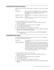
... devices, there are populated and a serial ATA drive is set Security Profile by Device, do the following : 1. Start the IBM Setup Utility program (see "Starting the IBM Setup Utility program" on page 19). 2. From the IBM Setup Utility program menu, select Security. 3. Return to disable one or both parallel ATA controllers are options for configuring the serial and parallel IDE controllers. Using IDE Drives Setup In addition to Disable, all diskettes are treated as hard disk drives or the CD-ROM drive...
... devices, there are populated and a serial ATA drive is set Security Profile by Device, do the following : 1. Start the IBM Setup Utility program (see "Starting the IBM Setup Utility program" on page 19). 2. From the IBM Setup Utility program menu, select Security. 3. Return to disable one or both parallel ATA controllers are options for configuring the serial and parallel IDE controllers. Using IDE Drives Setup In addition to Disable, all diskettes are treated as hard disk drives or the CD-ROM drive...
Hardware Maintenance Manual
Page 44
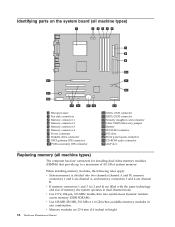
... system board (all machine types) 1 Microprocessor 2 Fan sink connectors 3 Memory connector 1 4 Memory connector 2 5 Memory connector 3 6 Memory connector 4 7 Power connector 8 Diskette drive connector 9 PATA primary IDE connector 10 PATA secondary IDE connector 11 SATA 1 IDE connector 12 SATA 2 IDE connector 13 Security daughter card connector 14 Clear CMOS/Recovery jumper 15 Battery 16 SCSI LED connector 17 PCI slots 18 Front panel audio connector 19 CD-ROM audio connector 20 AGP slot Replacing memory (all machine types) The computer has four connectors for installing dual inline memory...
... system board (all machine types) 1 Microprocessor 2 Fan sink connectors 3 Memory connector 1 4 Memory connector 2 5 Memory connector 3 6 Memory connector 4 7 Power connector 8 Diskette drive connector 9 PATA primary IDE connector 10 PATA secondary IDE connector 11 SATA 1 IDE connector 12 SATA 2 IDE connector 13 Security daughter card connector 14 Clear CMOS/Recovery jumper 15 Battery 16 SCSI LED connector 17 PCI slots 18 Front panel audio connector 19 CD-ROM audio connector 20 AGP slot Replacing memory (all machine types) The computer has four connectors for installing dual inline memory...
Hardware Maintenance Manual
Page 70
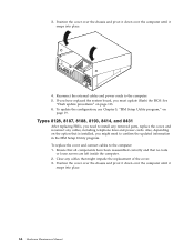
.... 4. Types 8128, 8187, 8188, 8193, 8414, and 8431 After replacing FRUs, you need to install any removed parts, replace the cover, and reconnect any cables that might need to confirm the updated information in the IBM Setup Utility program. Reconnect the external cables and power cords to the computer: 1. To replace the cover and connect cables to the computer. 5. 3. Also, depending on the option that no tools or loose screws are left inside the...
.... 4. Types 8128, 8187, 8188, 8193, 8414, and 8431 After replacing FRUs, you need to install any removed parts, replace the cover, and reconnect any cables that might need to confirm the updated information in the IBM Setup Utility program. Reconnect the external cables and power cords to the computer: 1. To replace the cover and connect cables to the computer. 5. 3. Also, depending on the option that no tools or loose screws are left inside the...
Hardware Maintenance Manual
Page 82
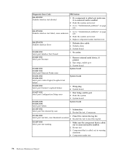
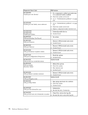
..., make sure it is connected and/or enabled 2. Go to reset the log file 011-197-XXX Serial port test warning 1. Wrap plug 2. Re-run test 3. Go to review the log file Serial port test halt, error threshold exceeded 2. Flash the system 3. If a component is called out in warning statement 4. Flash the system and re-test 3. Replace component under test 76 Hardware Maintenance Manual Diskette drive cable 2. No action 011-001-XXX Serial port Presence 1. System board 011...
..., make sure it is connected and/or enabled 2. Go to reset the log file 011-197-XXX Serial port test warning 1. Wrap plug 2. Re-run test 3. Go to review the log file Serial port test halt, error threshold exceeded 2. Flash the system 3. If a component is called out in warning statement 4. Flash the system and re-test 3. Replace component under test 76 Hardware Maintenance Manual Diskette drive cable 2. No action 011-001-XXX Serial port Presence 1. System board 011...
Hardware Maintenance Manual
Page 84
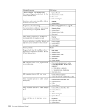
...test 3. Replace component under function test 1. Remove USB device(s) and re-test 2. System board 1. Flash the system 2. Run memory test 4. Remove USB device(s) and re-test 2. Press F3 to reset the log file 78 Hardware Maintenance Manual Go to "Undetermined problems" on page 109 2. Flash the system 3. System board System board 1. Run setup and check for conflicts 2. System board 1. System board 1. System board 1. System board System board 1. System board 1. Flash the system and re-test 3. No action 1. Diagnostic Error Code 014-198-XXX Parallel port...
...test 3. Replace component under function test 1. Remove USB device(s) and re-test 2. System board 1. Flash the system 2. Run memory test 4. Remove USB device(s) and re-test 2. Press F3 to reset the log file 78 Hardware Maintenance Manual Go to "Undetermined problems" on page 109 2. Flash the system 3. System board System board 1. Run setup and check for conflicts 2. System board 1. System board 1. System board 1. System board System board 1. System board 1. Flash the system and re-test 3. No action 1. Diagnostic Error Code 014-198-XXX Parallel port...

Hardware Maintenance Manual
Page 99
... "Recovering from a POST/BIOS update failure" on page 19.) 2. Adapter Memory 2. Riser card 1. Symptom-to "Replacing the battery (all machine types)" on computer 4. CMOS Backup Battery. System Board 1. Run Flash Recovery using Boot Block. Go to -FRU Index 93 Power-on external devices first, then power-on page 56 3. L2 Cache Memory 3. System board System Board 1. System Board Chapter 7. POST Error Code 111 I/O channel parity error 114 Adapter ROM error 129 Internal cache test error 135 Fan failure 151 System board failure 161 Bad CMOS battery 162 Configuration mismatch 163 Date and...
... "Recovering from a POST/BIOS update failure" on page 19.) 2. Adapter Memory 2. Riser card 1. Symptom-to "Replacing the battery (all machine types)" on computer 4. CMOS Backup Battery. System Board 1. Run Flash Recovery using Boot Block. Go to -FRU Index 93 Power-on external devices first, then power-on page 56 3. L2 Cache Memory 3. System board System Board 1. System Board Chapter 7. POST Error Code 111 I/O channel parity error 114 Adapter ROM error 129 Internal cache test error 135 Fan failure 151 System board failure 161 Bad CMOS battery 162 Configuration mismatch 163 Date and...

Hardware Maintenance Manual
Page 100
... Board 1. Covers were removed from the computer System Board System Board System Board 1. System Board Set configuration and reinstall the boot sequence System Board 1. System Board More than three password attempts were made to see that Ethernet and Alert on LAN are enabled in the IBM Setup Utility program. 2. Run Setup. RFID Antenna 3. Run Setup. Clear Administration password 2. POST Error Code 167 No Processor BIOS Update Found 168 Alert on page 19. 2. Check to access the computer System Board System Board System Board System Board...
... Board 1. Covers were removed from the computer System Board System Board System Board 1. System Board Set configuration and reinstall the boot sequence System Board 1. System Board More than three password attempts were made to see that Ethernet and Alert on LAN are enabled in the IBM Setup Utility program. 2. Run Setup. RFID Antenna 3. Run Setup. Clear Administration password 2. POST Error Code 167 No Processor BIOS Update Found 168 Alert on page 19. 2. Check to access the computer System Board System Board System Board System Board...
Hardware Maintenance Manual
Page 114
...2. Check the network adapter LED status Serial or parallel port device failure (system board port) 1. External Device 3. Alternate Adapter 5. Keyboard 2. Riser card Other display symptoms not listed above (including blank or illegible display) 1. System Board 3. First device - Hard disk drive RPL computer does not RPL from left to right of 1. External Device Self-Test OK? 2. Cable 4. Cable 4. Keyboard Cable 3. Diskette Drive Cable 3. Network Adapter Intensity or color varies from server 1. System Board No power or fan not running See "Power Supply Errors" on...
...2. Check the network adapter LED status Serial or parallel port device failure (system board port) 1. External Device 3. Alternate Adapter 5. Keyboard 2. Riser card Other display symptoms not listed above (including blank or illegible display) 1. System Board 3. First device - Hard disk drive RPL computer does not RPL from left to right of 1. External Device Self-Test OK? 2. Cable 4. Cable 4. Keyboard Cable 3. Diskette Drive Cable 3. Network Adapter Intensity or color varies from server 1. System Board No power or fan not running See "Power Supply Errors" on...

Hardware Maintenance Manual
Page 117
... "Identifying parts on the system board (all machine types)" on . See Chapter 5, "IBM Setup Utility program," on the computer. When a power-on password is active, the password prompt appears on the screen each time the computer is complete. Removing a power-on password To service a computer with an active and unknown power-on LAN Passwords The following procedure. Reset the date and time and remind the user to enter a new password when service is powered on...
... "Identifying parts on the system board (all machine types)" on . See Chapter 5, "IBM Setup Utility program," on the computer. When a power-on password is active, the password prompt appears on the screen each time the computer is complete. Removing a power-on password To service a computer with an active and unknown power-on LAN Passwords The following procedure. Reset the date and time and remind the user to enter a new password when service is powered on...
Hardware Maintenance Manual
Page 120
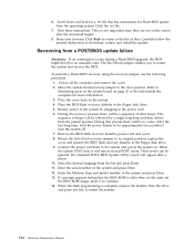
... the label inside the computer for Flash BIOS update from the operating system. Print these instructions. Recovering from the drive and press any key to restart the system. 114 Hardware Maintenance Manual Move the system board recovery jumper to download, extract, and install the update. Refer to continue. 14. During this process there will report several POST errors. Enter the Machine Type and model number of beeps will be followed by plugging in the power cord...
... the label inside the computer for Flash BIOS update from the operating system. Print these instructions. Recovering from the drive and press any key to restart the system. 114 Hardware Maintenance Manual Move the system board recovery jumper to download, extract, and install the update. Refer to continue. 14. During this process there will report several POST errors. Enter the Machine Type and model number of beeps will be followed by plugging in the power cord...
Hardware Maintenance Manual
Page 126
... 11M) Diskette drive, 1.44 MB, 3.5″, 2 mode (w/ bezel) (models 11M) Speaker assembly (all models) Pivot lock, 3.5 diskette drive (all models) Chassis/top cover kit (all models) Misc. Item # 4 4 4 5 6 6 6 6 7 8 9 10 11 11 12 13 13 8128 FRUs CD-ROM Drive 48X - hardware kit (all models) Cable, CDROM audio (all models) Hard disk drive mounting bracket assembly (all models) Cable assembly, power/LED (all models) Cable, second serial port (all models) Cable, dual USB 2.0 (all models) Battery, 3.0 V (all models) Monitor cable (all models) Dongle (all models) Mouse, optical wheel (models 11M...
... 11M) Diskette drive, 1.44 MB, 3.5″, 2 mode (w/ bezel) (models 11M) Speaker assembly (all models) Pivot lock, 3.5 diskette drive (all models) Chassis/top cover kit (all models) Misc. Item # 4 4 4 5 6 6 6 6 7 8 9 10 11 11 12 13 13 8128 FRUs CD-ROM Drive 48X - hardware kit (all models) Cable, CDROM audio (all models) Hard disk drive mounting bracket assembly (all models) Cable assembly, power/LED (all models) Cable, second serial port (all models) Cable, dual USB 2.0 (all models) Battery, 3.0 V (all models) Monitor cable (all models) Dongle (all models) Mouse, optical wheel (models 11M...

Hardware Maintenance Manual
Page 236
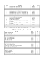
... 37L5098 59P8571 59P8572 59P8564 32P4743 22P4447 09N5764 75H9219 03K9655 59P8543 59P8549 49P4365 59P8545 49P1933 59P8587 230 Hardware Maintenance Manual CRU * * ** ** N N N CRU hardware kit (all models) Cable, CDROM audio (all models) Rubber foot (all models) Hard disk drive bracket assembly (all models) Hard disk drive tray (dampened) (all models) Cable, dual USB 2.0 (all models) Control panel assembly (all models) Audio cable assembly (ATA) (all models) PCMCIA assembly (all models) Fan assembly, 80 mm, fixed speed (models with 3.06GHz microprocessor or greater) Misc.
... 37L5098 59P8571 59P8572 59P8564 32P4743 22P4447 09N5764 75H9219 03K9655 59P8543 59P8549 49P4365 59P8545 49P1933 59P8587 230 Hardware Maintenance Manual CRU * * ** ** N N N CRU hardware kit (all models) Cable, CDROM audio (all models) Rubber foot (all models) Hard disk drive bracket assembly (all models) Hard disk drive tray (dampened) (all models) Cable, dual USB 2.0 (all models) Control panel assembly (all models) Audio cable assembly (ATA) (all models) PCMCIA assembly (all models) Fan assembly, 80 mm, fixed speed (models with 3.06GHz microprocessor or greater) Misc.


