User Guide
Page 5
... static-sensitive devices 5 Installing external options 6 Locating the connectors on the front of your computer 7 Locating the connectors on the system board . . . . . 11 Installing memory 12 Installing adapters 14 Installing internal drives 16 Drive specifications 16 Installing a drive 17 Installing security features 20 Padlock loop 21 Password protection 21 Changing the battery 21 Erasing a lost or forgotten password (clearing CMOS 23 Replacing the cover and connecting the cables. . . 23 Chapter 2. Cleaning the mouse . . . 31 Cleaning an optical mouse 31 Cleaning a mouse with...
... static-sensitive devices 5 Installing external options 6 Locating the connectors on the front of your computer 7 Locating the connectors on the system board . . . . . 11 Installing memory 12 Installing adapters 14 Installing internal drives 16 Drive specifications 16 Installing a drive 17 Installing security features 20 Padlock loop 21 Password protection 21 Changing the battery 21 Erasing a lost or forgotten password (clearing CMOS 23 Replacing the cover and connecting the cables. . . 23 Chapter 2. Cleaning the mouse . . . 31 Cleaning an optical mouse 31 Cleaning a mouse with...
User Guide
Page 14
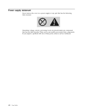
Power supply statement Never remove the cover on a power supply or any component that has the following label attached. There are present inside these parts, contact a service technician. xii User Guide If you suspect a problem with one of these components. Hazardous voltage, current, and energy levels are no serviceable parts inside any part that has this label attached.
Power supply statement Never remove the cover on a power supply or any component that has the following label attached. There are present inside these parts, contact a service technician. xii User Guide If you suspect a problem with one of these components. Hazardous voltage, current, and energy levels are no serviceable parts inside any part that has this label attached.

User Guide
Page 15
... option. Portions © IBM Corp. 2004,2005. It also includes basic troubleshooting information, software recovery procedures, help and service information, and warranty information. If you for installing external and internal options are included in computer technology and can find the following information: v CRU removal and installation instructions v Publications v Troubleshooting information v Parts information v Downloads and drivers v Links to increase its capabilities. Your computer incorporates many of information v Support phone list...
... option. Portions © IBM Corp. 2004,2005. It also includes basic troubleshooting information, software recovery procedures, help and service information, and warranty information. If you for installing external and internal options are included in computer technology and can find the following information: v CRU removal and installation instructions v Publications v Troubleshooting information v Parts information v Downloads and drivers v Links to increase its capabilities. Your computer incorporates many of information v Support phone list...
User Guide
Page 17
... features and preinstalled software. Note: Use only the parts provided by model type) © Lenovo 2005. See Chapter 2, "Using the Setup Utility program," on page v. Microprocessor (varies by adding memory, adapters, or drives. Chapter 1. Installing options ThinkCentre Features This chapter provides an introduction to the features and options that come with the option. For information for your computer by model type) v Intel® Pentium® 4 processor with the instructions that are...
... features and preinstalled software. Note: Use only the parts provided by model type) © Lenovo 2005. See Chapter 2, "Using the Setup Utility program," on page v. Microprocessor (varies by adding memory, adapters, or drives. Chapter 1. Installing options ThinkCentre Features This chapter provides an introduction to the features and options that come with the option. For information for your computer by model type) v Intel® Pentium® 4 processor with the instructions that are...
User Guide
Page 18
Memory v Support for four double data rate (DDR or DDR2, depending on model) dual inline memory modules (DIMMs) v 512 KB flash memory for system programs Internal drives v 3.5-inch, 1.44 MB diskette drive v Serial Advanced Technology Attachment (SATA) internal hard disk drive v Optical drive (some models) Video subsystem v An integrated graphics controller for a Video Graphics Array (VGA) monitor v PCI Express (x16) graphics adapter connector on the system board Audio subsystem v AC'97 with ADI 1981B Audio Codec v Line in and line out connectors on the rear panel v Microphone and headphone...
Memory v Support for four double data rate (DDR or DDR2, depending on model) dual inline memory modules (DIMMs) v 512 KB flash memory for system programs Internal drives v 3.5-inch, 1.44 MB diskette drive v Serial Advanced Technology Attachment (SATA) internal hard disk drive v Optical drive (some models) Video subsystem v An integrated graphics controller for a Video Graphics Array (VGA) monitor v PCI Express (x16) graphics adapter connector on the system board Audio subsystem v AC'97 with ADI 1981B Audio Codec v Line in and line out connectors on the rear panel v Microphone and headphone...

User Guide
Page 19
...switching v Advanced Power Management support v Advanced Configuration and Power Interface (ACPI) support Security features v User and administrator passwords for BIOS access v User and master passwords for hard disk drive (some models) v Support for the addition of a padlock to secure the cover v Keyboard with fingerprint reader (some models, see the Access IBM program for more information) v Cover presence switch (some models) v Startup sequence control v Startup without diskette drive, keyboard, or mouse v Unattended start mode v Diskette and hard disk I/O control v Serial and parallel port...
...switching v Advanced Power Management support v Advanced Configuration and Power Interface (ACPI) support Security features v User and administrator passwords for BIOS access v User and master passwords for hard disk drive (some models) v Support for the addition of a padlock to secure the cover v Keyboard with fingerprint reader (some models, see the Access IBM program for more information) v Cover presence switch (some models) v Startup sequence control v Startup without diskette drive, keyboard, or mouse v Unattended start mode v Diskette and hard disk I/O control v Serial and parallel port...
User Guide
Page 24
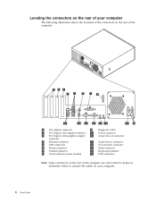
... connectors on the rear of the computer. 1 PCI adapter connector 9 Diagnostic LEDs 2 PCI Express (x1) adapter connector 10 Power connector 3 PCI Express (x16) graphics adapter 11 Audio line out connector connector 4 Ethernet connector 12 Audio line in connector 5 USB connectors 13 VGA monitor connector 6 Mouse connector 14 Serial connector 7 Parallel connector 15 Keyboard connector 8 Serial connector (some models) 16 USB connectors Note: Some connectors on the rear of the computer are color-coded to help you determine where to connect the cables on your computer. 8 User Guide
... connectors on the rear of the computer. 1 PCI adapter connector 9 Diagnostic LEDs 2 PCI Express (x1) adapter connector 10 Power connector 3 PCI Express (x16) graphics adapter 11 Audio line out connector connector 4 Ethernet connector 12 Audio line in connector 5 USB connectors 13 VGA monitor connector 6 Mouse connector 14 Serial connector 7 Parallel connector 15 Keyboard connector 8 Serial connector (some models) 16 USB connectors Note: Some connectors on the rear of the computer are color-coded to help you determine where to connect the cables on your computer. 8 User Guide

User Guide
Page 25
..., multimedia keyboards, or the audio line in connector of the computer. Serial connectors Used to external devices, such as powered stereo speakers (speakers with the device-driver files. Audio line out connector Used to send audio signals from an external audio device, such as a USB scanner or USB printer. Obtaining device drivers You can use a Category 5 Ethernet cable. Installation instructions are not preinstalled at http://www.lenovo.com/think/support on a stereo system or other devices that uses a standard keyboard connector. Note: To operate the...
..., multimedia keyboards, or the audio line in connector of the computer. Serial connectors Used to external devices, such as powered stereo speakers (speakers with the device-driver files. Audio line out connector Used to send audio signals from an external audio device, such as a USB scanner or USB printer. Obtaining device drivers You can use a Category 5 Ethernet cable. Installation instructions are not preinstalled at http://www.lenovo.com/think/support on a stereo system or other devices that uses a standard keyboard connector. Note: To operate the...

User Guide
Page 28
... operates in both channels, your computer. 12 User Guide The type of memory required depends on the system board. 1 12v power connector 2 Diskette drive connector 3 Speaker connector 4 Memory connector 4 5 Memory connector 3 6 Memory connector 2 7 Memory connector 1 8 Clear CMOS/Recovery jumper 9 Front panel connector 10 PATA IDE connector 11 SATA 4 connector 12 SATA 3 connector 13 SATA 2 connector 14 SATA 1 connector 15 Cover presence switch connector 16 Power supply connector 17 PCI Express (x16) graphics adapter connector 18 PCI Express (x1) adapter connector...
... operates in both channels, your computer. 12 User Guide The type of memory required depends on the system board. 1 12v power connector 2 Diskette drive connector 3 Speaker connector 4 Memory connector 4 5 Memory connector 3 6 Memory connector 2 7 Memory connector 1 8 Clear CMOS/Recovery jumper 9 Front panel connector 10 PATA IDE connector 11 SATA 4 connector 12 SATA 3 connector 13 SATA 2 connector 14 SATA 1 connector 15 Cover presence switch connector 16 Power supply connector 17 PCI Express (x16) graphics adapter connector 18 PCI Express (x1) adapter connector...
User Guide
Page 29
... memory installed. Installing options 13 The type of memory required is also indicated in the ″System Summary″ section of the Setup Utility or the operating system might be used in any combination of the system board are a yellow color, your system board has DDR2 type memory. Chapter 1. Notes: a. This discrepancy is due to the edge of 128 MB, 256 MB, 512 MB, and 1 GB sizes. 1. b. System memory...
... memory installed. Installing options 13 The type of memory required is also indicated in the ″System Summary″ section of the Setup Utility or the operating system might be used in any combination of the system board are a yellow color, your system board has DDR2 type memory. Chapter 1. Notes: a. This discrepancy is due to the edge of 128 MB, 256 MB, 512 MB, and 1 GB sizes. 1. b. System memory...
User Guide
Page 33
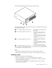
...-inch removable media drive v Optical drive such as CD drive or DVD drive v 3.5-inch hard disk drive (requires a Universal Adapter Bracket, 5.25 to 3.5-inch) * 3 Bay 3 - Maximum height: 43.0 mm (1.7 in some models) v 3.5-inch hard disk drive (requires a Universal Adapter Bracket, 5.25 to 3.5-inch) * v 5.25-inch removable media drive 4 Bay 4 - Drives that you can obtain a Universal Adapter Bracket, 5.25 to remove the signal and power cables from the front bezel. Notes: 1. Remove the computer cover. Installing a drive To install an internal drive, follow...
...-inch removable media drive v Optical drive such as CD drive or DVD drive v 3.5-inch hard disk drive (requires a Universal Adapter Bracket, 5.25 to 3.5-inch) * 3 Bay 3 - Maximum height: 43.0 mm (1.7 in some models) v 3.5-inch hard disk drive (requires a Universal Adapter Bracket, 5.25 to 3.5-inch) * v 5.25-inch removable media drive 4 Bay 4 - Drives that you can obtain a Universal Adapter Bracket, 5.25 to remove the signal and power cables from the front bezel. Notes: 1. Remove the computer cover. Installing a drive To install an internal drive, follow...

User Guide
Page 36
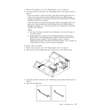
... SATA connector on page 23. Your computer has extra power connectors for additional drives. Connecting a serial ATA hard disk drive A serial hard disk drive can be connected to do next v To work with the new drive. 2. Locate the signal cable that locks the keyboard until a correct password is typed in. 20 User Guide What to any available SATA connector. 1. Locate an available SATA connector on the system board and the three-connector signal cable. Connect one end of your computer, security lock options are available. Installing...
... SATA connector on page 23. Your computer has extra power connectors for additional drives. Connecting a serial ATA hard disk drive A serial hard disk drive can be connected to do next v To work with the new drive. 2. Locate the signal cable that locks the keyboard until a correct password is typed in. 20 User Guide What to any available SATA connector. 1. Locate an available SATA connector on the system board and the three-connector signal cable. Connect one end of your computer, security lock options are available. Installing...

User Guide
Page 39
... 10. 2. Clear any adapters that is installed, you need to your computer. 2. See "Identifying parts on the system board" on the system board. Move the jumper from the standard position (pins 1 and 2) to the system board. * XXXXXXXXX* * XXXXXXXXX* 3. To replace the computer cover and connect cables to confirm the updated information in the Setup Utility program. Move the jumper back to the Clear CMOS/Recovery jumper. 5. Replacing the cover and connecting the cables After working with options, you...
... 10. 2. Clear any adapters that is installed, you need to your computer. 2. See "Identifying parts on the system board" on the system board. Move the jumper from the standard position (pins 1 and 2) to the system board. * XXXXXXXXX* * XXXXXXXXX* 3. To replace the computer cover and connect cables to confirm the updated information in the Setup Utility program. Move the jumper back to the Clear CMOS/Recovery jumper. 5. Replacing the cover and connecting the cables After working with options, you...

User Guide
Page 41
... and changing settings The Setup Utility program menu lists items that hardware has been removed or new hardware has been installed in your computer, you are using a USB keyboard and the Setup Utility program does not display using this procedure, shut down the operating system and turn on the computer. The keys used to use the keyboard. Password considerations If you type your computer. See "Using passwords" for more information. If a user password or an administrator password has been set passwords to prevent...
... and changing settings The Setup Utility program menu lists items that hardware has been removed or new hardware has been installed in your computer, you are using a USB keyboard and the Setup Utility program does not display using this procedure, shut down the operating system and turn on the computer. The keys used to use the keyboard. Password considerations If you type your computer. See "Using passwords" for more information. If a user password or an administrator password has been set passwords to prevent...

User Guide
Page 42
... Drive Master password can reset the IDE Drive User Password. 26 User Guide v If you set , there is no IDE Drive Master Password is set both a User Password and an IDE Drive User Password and each time the computer is connected to type a valid password each password is typed from changing configuration settings. If you are prompted to protect the data on your computer has multiple hard disk drives, they all must be used to type a valid password before any configuration settings, you turn...
... Drive Master password can reset the IDE Drive User Password. 26 User Guide v If you set , there is no IDE Drive Master Password is set both a User Password and an IDE Drive User Password and each time the computer is connected to type a valid password each password is typed from changing configuration settings. If you are prompted to protect the data on your computer has multiple hard disk drives, they all must be used to type a valid password before any configuration settings, you turn...

User Guide
Page 43
... configuration. Attention Make sure that the IDE Drive Master password is set to Enable, all devices connected to the IDE controller (such as hard disk drives or the CD-ROM drive) are disabled and will not be displayed in a safe place. From the Setup Utility program menu, select Security. 3. Selecting a startup device If your computer does not start up to seven characters (A- Setting, changing, and deleting a password To set, change, or delete a password, do the following devices: IDE controller Diskette Drive Access...
... configuration. Attention Make sure that the IDE Drive Master password is set to Enable, all devices connected to the IDE controller (such as hard disk drives or the CD-ROM drive) are disabled and will not be displayed in a safe place. From the Setup Utility program menu, select Security. 3. Selecting a startup device If your computer does not start up to seven characters (A- Setting, changing, and deleting a password To set, change, or delete a password, do the following devices: IDE controller Diskette Drive Access...
User Guide
Page 45
...://www.lenovo.com/think /support in the seven character machine type/model of your computer then press Enter. 8. Type in the address field and press Enter. © Lenovo 2005. System program updates are available as flash memory). Lenovo might make changes and enhancements to change the machine type/model, press Y. 7. You can use the Setup Utility program to complete the update. From your operating system. Portions © IBM Corp. 2004,2005. 29...
...://www.lenovo.com/think /support in the seven character machine type/model of your computer then press Enter. 8. Type in the address field and press Enter. © Lenovo 2005. System program updates are available as flash memory). Lenovo might make changes and enhancements to change the machine type/model, press Y. 7. You can use the Setup Utility program to complete the update. From your operating system. Portions © IBM Corp. 2004,2005. 29...

User Guide
Page 46
.... 3. See "Replacing the cover and connecting the cables" on page 11. 5. Pivot the drive bay assembly upward to gain access to pins 2 and 3. 7. Move the jumper from the standard position (pins 1 and 2) to the system board. 4. Locate the Downloadable files for the flash BIOS update (flash from a POST/BIOS update failure If power to its original position. 13. b. Recovering from the operating system version). 3. Locate the Clear CMOS/Recovery jumper on page 23. 8. Replace the Clear CMOS/Recovery jumper to your...
.... 3. See "Replacing the cover and connecting the cables" on page 11. 5. Pivot the drive bay assembly upward to gain access to pins 2 and 3. 7. Move the jumper from the standard position (pins 1 and 2) to the system board. 4. Locate the Downloadable files for the flash BIOS update (flash from a POST/BIOS update failure If power to its original position. 13. b. Recovering from the operating system version). 3. Locate the Clear CMOS/Recovery jumper on page 23. 8. Replace the Clear CMOS/Recovery jumper to your...

User Guide
Page 52
e=0-1; and f=0-1. Parameter ″b″ specifies automode operations where: 0=automode disabled, 1= automode enabled with fallback options Normal data link only (same as Profile 1 Disable auto-retrain Enable auto-retrain Displays the current Select Modulation settings Displays a list of support values 36 User Guide Parameter ″e″ specifies the codec type (0= Law, and 1=A-Law). d=30056000; Parameter ″a″ specifies the modulation protocol desired where: 0=V.21, 1=V.22, 2=V.22bis...
e=0-1; and f=0-1. Parameter ″b″ specifies automode operations where: 0=automode disabled, 1= automode enabled with fallback options Normal data link only (same as Profile 1 Disable auto-retrain Enable auto-retrain Displays the current Select Modulation settings Displays a list of support values 36 User Guide Parameter ″e″ specifies the codec type (0= Law, and 1=A-Law). d=30056000; Parameter ″a″ specifies the modulation protocol desired where: 0=V.21, 1=V.22, 2=V.22bis...
User Guide
Page 59
...connector 9 audio, subsystem 2 B battery location 11 boot-block recovery 30 C cables, connecting 23 changing the battery 21 cleaning the mouse 31 commands Basic AT 33 Extended AT 35 Fax Class 1 37 Fax Class 2 37 MNP/V.42/V.42bis/V.44 36 Voice 38 connector description 9 cover removing 10 replacing 23 D device, drivers 9 drives bays 3, 16 diskette 5 hard disk 5 installing 17 internal 2, 16 optical 5 removable media 5 specifications 16 E environment, operating 4 Ethernet connector 9 I information resources xiii input/output (I/O) features 2 installing options adapters 14 internal drives 17 memory...
...connector 9 audio, subsystem 2 B battery location 11 boot-block recovery 30 C cables, connecting 23 changing the battery 21 cleaning the mouse 31 commands Basic AT 33 Extended AT 35 Fax Class 1 37 Fax Class 2 37 MNP/V.42/V.42bis/V.44 36 Voice 38 connector description 9 cover removing 10 replacing 23 D device, drivers 9 drives bays 3, 16 diskette 5 hard disk 5 installing 17 internal 2, 16 optical 5 removable media 5 specifications 16 E environment, operating 4 Ethernet connector 9 I information resources xiii input/output (I/O) features 2 installing options adapters 14 internal drives 17 memory...


