
Service Guide
Page 3
... Drawer Rear View 14 Primary I /O Drawer Operator Panel 24 SCSI IDs and Bay Locations 25 System Memory 26 One-Way Processor Memory Placement Rules 26 iii Contents Safety Notices xi Rack Safety Instructions xi Electrical Safety xii Laser Safety Information xiii Laser Compliance ... xvii ISO 9000 xvii Online Publications xvii Related Publications xvii Trademarks xviii Chapter 1. Reference Information 1 Overview 1 Data Flow with One-Way Processor 3 Data Flow with Covers Removed 15 Secondary I/O Drawer Front View 16 Secondary I/O Drawer Top View 16 Secondary I/O Drawer Rear View...
... Drawer Rear View 14 Primary I /O Drawer Operator Panel 24 SCSI IDs and Bay Locations 25 System Memory 26 One-Way Processor Memory Placement Rules 26 iii Contents Safety Notices xi Rack Safety Instructions xi Electrical Safety xii Laser Safety Information xiii Laser Compliance ... xvii ISO 9000 xvii Online Publications xvii Related Publications xvii Trademarks xviii Chapter 1. Reference Information 1 Overview 1 Data Flow with One-Way Processor 3 Data Flow with Covers Removed 15 Secondary I/O Drawer Front View 16 Secondary I/O Drawer Top View 16 Secondary I/O Drawer Rear View...
Service Guide
Page 4
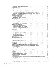
... I/O Drawer Features 27 I/O Drawer Addressing 27 I/O Drawer and Power Supply LED Status 28 Message Hierarchy for the pSeries and RS/6000 71 Eserver Using the Service Processor and Electronic Service Agent Features 72 Service Processor 72 Electronic Service Agent 73 Chapter 3. Maintenance Analysis Procedures (MAPs 75 Entry MAP 75 Quick Entry MAP 76 Quick...
... I/O Drawer Features 27 I/O Drawer Addressing 27 I/O Drawer and Power Supply LED Status 28 Message Hierarchy for the pSeries and RS/6000 71 Eserver Using the Service Processor and Electronic Service Agent Features 72 Service Processor 72 Electronic Service Agent 73 Chapter 3. Maintenance Analysis Procedures (MAPs 75 Entry MAP 75 Quick Entry MAP 76 Quick...
Service Guide
Page 5
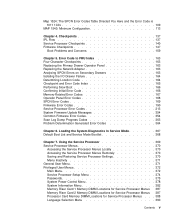
... Code 166 Memory-Related Error Codes 167 Operator Panel Error Codes 168 SPCN Error Codes 169 Firmware Error Codes 190 Service Processor Error Codes 213 System Firmware Update Messages 354 Common Firmware Error Codes 354 Scan Log Dump Progress Codes 363 Problem Determination ...Power Control Menu System Information Menu Memory Riser Card 1 Memory DIMM Locations for Service Processor Menus Memory Riser Card 2 Memory DIMM Locations for Service Processor Menus Processor Card Memory DIMM Locations for Service Processor Menus . . Map 1524: The SPCN Error Codes Table Directed You Here and the...
... Code 166 Memory-Related Error Codes 167 Operator Panel Error Codes 168 SPCN Error Codes 169 Firmware Error Codes 190 Service Processor Error Codes 213 System Firmware Update Messages 354 Common Firmware Error Codes 354 Scan Log Dump Progress Codes 363 Problem Determination ...Power Control Menu System Information Menu Memory Riser Card 1 Memory DIMM Locations for Service Processor Menus Memory Riser Card 2 Memory DIMM Locations for Service Processor Menus Processor Card Memory DIMM Locations for Service Processor Menus . . Map 1524: The SPCN Error Codes Table Directed You Here and the...

Service Guide
Page 6
... Setup Menu 394 Call-Out Policy Setup Menu 395 Customer Account Setup Menu 396 Service Processor Procedures in Service Mode 396 Service Processor Functions 397 System Power-On Methods 398 Service Processor Reboot/Restart Recovery 399 Boot (IPL) Speed 399 Failure During Boot Process 399 Failure ...the Level of Firmware on the System 402 System Firmware Update Using a Locally Available Image 402 Updating System Firmware From the Service Processor Menus 403 Updating System Firmware from the AIX Service Aids 403 Updating System Firmware from the AIX Command Line 403 Recovery Mode ...
... Setup Menu 394 Call-Out Policy Setup Menu 395 Customer Account Setup Menu 396 Service Processor Procedures in Service Mode 396 Service Processor Functions 397 System Power-On Methods 398 Service Processor Reboot/Restart Recovery 399 Boot (IPL) Speed 399 Failure During Boot Process 399 Failure ...the Level of Firmware on the System 402 System Firmware Update Using a Locally Available Image 402 Updating System Firmware From the Service Processor Menus 403 Updating System Firmware from the AIX Service Aids 403 Updating System Firmware from the AIX Command Line 403 Recovery Mode ...

Service Guide
Page 7
...Powering On the System 429 Powering Off the System 429 Powering On the System 429 Powering Off and Powering On the System Using the Service Processor . . . 429 Hot-Pluggable FRUs 430 I/O Drawer PCI Slot LED Definitions 430 PCI Adapters 431 Non-Hot-Pluggable PCI Adapter 431 Removal... Accessing Hot-Plug Management Functions 438 PCI Hot-Plug Manager Menu 438 Memory Riser Cards and Memory DIMMs 441 Removal 441 Replacement 442 Processor Card 443 Removal 443 Replacement 443 CEC Fans 444 Removal 444 Replacement 444 CEC Backplane 445 Removal 445 Replacement 446 I/O Drawer Backplane ...
...Powering On the System 429 Powering Off the System 429 Powering On the System 429 Powering Off and Powering On the System Using the Service Processor . . . 429 Hot-Pluggable FRUs 430 I/O Drawer PCI Slot LED Definitions 430 PCI Adapters 431 Non-Hot-Pluggable PCI Adapter 431 Removal... Accessing Hot-Plug Management Functions 438 PCI Hot-Plug Manager Menu 438 Memory Riser Cards and Memory DIMMs 441 Removal 441 Replacement 442 Processor Card 443 Removal 443 Replacement 443 CEC Fans 444 Removal 444 Replacement 444 CEC Backplane 445 Removal 445 Replacement 446 I/O Drawer Backplane ...

Service Guide
Page 8
... Panel 465 Removal 465 Replacement 466 Rear Service Position 467 Front Service Position 468 Battery 469 Removal 469 Replacement 470 Chapter 10. Service Processor Setup and Test 497 Service Processor Setup Checklist 497 Testing the Setup 498 Testing Call-In 498 Testing Call-Out 498 Serial Port Configuration 499 Appendix D. Modem Configurations...
... Panel 465 Removal 465 Replacement 466 Rear Service Position 467 Front Service Position 468 Battery 469 Removal 469 Replacement 470 Chapter 10. Service Processor Setup and Test 497 Service Processor Setup Checklist 497 Testing the Setup 498 Testing Call-In 498 Testing Call-Out 498 Serial Port Configuration 499 Appendix D. Modem Configurations...

Service Guide
Page 19
... one 450 MHz processor, which has 2 MB of L2 cache. v Six 500 MHz processors, each with 4 MB of L2 cache. v Six 750 MHz processors, each with 8 MB of the operator panel v Cabling rules v System location rules and descriptions v Powering on and off the system v Power flow v Data flow Overview The RS/6000 Enterprise Server Model H80, pSeries 660 Models...
... one 450 MHz processor, which has 2 MB of L2 cache. v Six 500 MHz processors, each with 4 MB of L2 cache. v Six 750 MHz processors, each with 8 MB of the operator panel v Cabling rules v System location rules and descriptions v Powering on and off the system v Power flow v Data flow Overview The RS/6000 Enterprise Server Model H80, pSeries 660 Models...

Service Guide
Page 20
... is connected from older RS/6000 systems can occupy PCI slots 13 and 14. or 64-bit PCI adapters. Two optional disk drives can also be used when upgrading the system memory. to Six-Way Processor" on page 3 and "Data Flow with One-Way Processor" on page 4. ...SPCN controller v Interrupt and system bus control logic v Service processor v Optional boot DASDs v Various connectors, including four serial port connectors, on serial port 3 or serial port 4. Memory v 256 MB (minimum) to each riser card has sixteen sockets. 128 MB, 256 MB, 512 MB, and 1 GB dual inline memory modules (DIMMs) are...
... is connected from older RS/6000 systems can occupy PCI slots 13 and 14. or 64-bit PCI adapters. Two optional disk drives can also be used when upgrading the system memory. to Six-Way Processor" on page 3 and "Data Flow with One-Way Processor" on page 4. ...SPCN controller v Interrupt and system bus control logic v Service processor v Optional boot DASDs v Various connectors, including four serial port connectors, on serial port 3 or serial port 4. Memory v 256 MB (minimum) to each riser card has sixteen sockets. 128 MB, 256 MB, 512 MB, and 1 GB dual inline memory modules (DIMMs) are...

Service Guide
Page 21
... 6XX Controller P Bus 0 SMI SMI SMI BUS 0, 1 Memory Card (1 only is optional) SMI BUS 2, 3 SMI SMI RIO SMI SMI (2) 256 MB - 16 GB 10/100 E'net 32-bit PCI Bus 0 SCSI Converged Support Processor PCI Host Bridge 64-bit PCI Bus 1 64-bit PCI Bus 2 PCI to PCI Bridge 1 PCI to PCI Bridge...
... 6XX Controller P Bus 0 SMI SMI SMI BUS 0, 1 Memory Card (1 only is optional) SMI BUS 2, 3 SMI SMI RIO SMI SMI (2) 256 MB - 16 GB 10/100 E'net 32-bit PCI Bus 0 SCSI Converged Support Processor PCI Host Bridge 64-bit PCI Bus 1 64-bit PCI Bus 2 PCI to PCI Bridge 1 PCI to PCI Bridge...

Service Guide
Page 22
... 1 P L2 P L2 Memory Cards (1 or 2) SMI BUS 0, 1 SMI BUS 2, 3 SMI SMI RIO SMI SMI (2) OR 4-Way System P L2 P L2 256 MB - 32 GB 32-bit PCI Bus 0 10/100 E'net SCSI Converged Support Processor PCI Host Bridge 64-bit PCI Bus 1 64-bit PCI Bus 2 PCI to PCI Bridge 1 PCI to PCI Bridge...
... 1 P L2 P L2 Memory Cards (1 or 2) SMI BUS 0, 1 SMI BUS 2, 3 SMI SMI RIO SMI SMI (2) OR 4-Way System P L2 P L2 256 MB - 32 GB 32-bit PCI Bus 0 10/100 E'net SCSI Converged Support Processor PCI Host Bridge 64-bit PCI Bus 1 64-bit PCI Bus 2 PCI to PCI Bridge 1 PCI to PCI Bridge...

Service Guide
Page 40
One-Way Processor Card Memory DIMM Locations (8) A (7) B (6) C (5) D (4) D (3) C (2) B (1) A Location Code U1.1-P1-C1-Mn U1.1-P1-C1-M1 x2 U1.1-P1-C1-M2 x2 U1.1-P1-C1-M3 x2 U1.1-P1-C1-M4 x2 U1.1-P1-C1-M1 x8 Memory DIMMs Memory DIMMs on processor card (n denotes DIMM number) Memory pair A (DIMMs 1 and 8) Memory pair B (DIMMs 2 and 7) Memory pair C (DIMMs 3 and 6) Memory pair D (DIMMs 4 and 5) All memory DIMMs on processor card 22 Service Guide
One-Way Processor Card Memory DIMM Locations (8) A (7) B (6) C (5) D (4) D (3) C (2) B (1) A Location Code U1.1-P1-C1-Mn U1.1-P1-C1-M1 x2 U1.1-P1-C1-M2 x2 U1.1-P1-C1-M3 x2 U1.1-P1-C1-M4 x2 U1.1-P1-C1-M1 x8 Memory DIMMs Memory DIMMs on processor card (n denotes DIMM number) Memory pair A (DIMMs 1 and 8) Memory pair B (DIMMs 2 and 7) Memory pair C (DIMMs 3 and 6) Memory pair D (DIMMs 4 and 5) All memory DIMMs on processor card 22 Service Guide

Service Guide
Page 41
... switch, you press the switch, the service processor resets and then shuts down the system. Reference Information 23 Primary I/O Drawer Operator Panel 1 2 3 6 5 4 1 3 5 R Power on/off button 2 Operator panel display 4 Service processor 6 reset button opening Power on/off LED ...Reset button Disturbance or system attention LED Note: The service processor reset button should feel the detent of a service action and must therefore be activated very carefully...
... switch, you press the switch, the service processor resets and then shuts down the system. Reference Information 23 Primary I/O Drawer Operator Panel 1 2 3 6 5 4 1 3 5 R Power on/off button 2 Operator panel display 4 Service processor 6 reset button opening Power on/off LED ...Reset button Disturbance or system attention LED Note: The service processor reset button should feel the detent of a service action and must therefore be activated very carefully...

Service Guide
Page 44
.... Riser Card Memory Placement Rules The rules for one -way processor card to the memory riser card. - v Quad memory size may be used. One-Way Processor Memory Placement Rules The rules for riser card memory are available: 128 MB, 256 MB, 512 MB and 1 GB. v Populate the riser card starting with quad... Minimum memory is slots 1, 2, 15, and 16 (see "One-Way Processor Card Memory DIMM Locations" on page 21). 26 Service Guide v The minimum memory is four DIMMs. This memory must be moved from earlier RS/6000 systems can also be mixed on page 22). System Memory Two slots are ...
.... Riser Card Memory Placement Rules The rules for one -way processor card to the memory riser card. - v Quad memory size may be used. One-Way Processor Memory Placement Rules The rules for riser card memory are available: 128 MB, 256 MB, 512 MB and 1 GB. v Populate the riser card starting with quad... Minimum memory is slots 1, 2, 15, and 16 (see "One-Way Processor Card Memory DIMM Locations" on page 21). 26 Service Guide v The minimum memory is four DIMMs. This memory must be moved from earlier RS/6000 systems can also be mixed on page 22). System Memory Two slots are ...

Service Guide
Page 45
... is displayed in the operator panel on secondary I /O drawer address temporarily displays in the form U0.n, where n is powered on which the SPCN and service processor logic reside. Chapter 1. I/O Drawer Features I /O drawer addressing refers to the drawer number that is booting up. The drawer number is displayed in the format *0n...
... is displayed in the operator panel on secondary I /O drawer address temporarily displays in the form U0.n, where n is powered on which the SPCN and service processor logic reside. Chapter 1. I/O Drawer Features I /O drawer addressing refers to the drawer number that is booting up. The drawer number is displayed in the format *0n...

Service Guide
Page 50
... The base location identifies a device that is part of the platform. Cable information identifies a cable that are examples: v P1-C1 identifies a processor card C1 plugged into the parent. v P2-Z1-A3.1 identifies a SCSI device with SCSI ID 3 attached to SCSI bus 1 on planar ...connectors or ports) to their specific locations within the physical structure of the parent, a connector, or a cable. v P1-C1.1 identifies processor 1 plugged into planar P1. Depending on a memory card, SCSI addresses, cables). Location codes with AIX location codes to provide mapping of ...
... The base location identifies a device that is part of the platform. Cable information identifies a cable that are examples: v P1-C1 identifies a processor card C1 plugged into the parent. v P2-Z1-A3.1 identifies a SCSI device with SCSI ID 3 attached to SCSI bus 1 on planar ...connectors or ports) to their specific locations within the physical structure of the parent, a connector, or a cable. v P1-C1.1 identifies processor 1 plugged into planar P1. Depending on a memory card, SCSI addresses, cables). Location codes with AIX location codes to provide mapping of ...

Service Guide
Page 51
... failing part may also be at the bottom of the command output. In this is an error code with memory DIMMs, memory riser cards, or processors and may be specified. If the location code includes a blank space followed by a lowercase x followed by a number, this case, check the ...system's configuration FRU part numbers to FRU Index" on page 163, a location code for processors and memory DIMMs may involve mixed types of parts. Multiple FRU Callout Instructions If an eight-digit error code appears in the operator panel display...
... failing part may also be at the bottom of the command output. In this is an error code with memory DIMMs, memory riser cards, or processors and may be specified. If the location code includes a blank space followed by a lowercase x followed by a number, this case, check the ...system's configuration FRU part numbers to FRU Index" on page 163, a location code for processors and memory DIMMs may involve mixed types of parts. Multiple FRU Callout Instructions If an eight-digit error code appears in the operator panel display...

Service Guide
Page 54
... U1.1-P1-C1-M4 x2 00-00 Physical Connection Logical Connection Connector M03 Refer to "One-Way Processor Card Memory DIMM Locations" on page 22. Refer to "One-Way Processor Card Memory DIMM Locations" on page 22. 36 Service Guide Refer to identify functional units in the system. Each... of the following tables contain location codes that are used to "One-Way Processor Card Memory DIMM Locations" on page 22. Refer to "One-Way Processor Card Memory DIMM Locations" on page 22. AIX and Physical Location Code Reference Tables The following tables shows...
... U1.1-P1-C1-M4 x2 00-00 Physical Connection Logical Connection Connector M03 Refer to "One-Way Processor Card Memory DIMM Locations" on page 22. Refer to "One-Way Processor Card Memory DIMM Locations" on page 22. 36 Service Guide Refer to identify functional units in the system. Each... of the following tables contain location codes that are used to "One-Way Processor Card Memory DIMM Locations" on page 22. Refer to "One-Way Processor Card Memory DIMM Locations" on page 22. AIX and Physical Location Code Reference Tables The following tables shows...

Service Guide
Page 55
.... Chapter 1. Refer to "Memory Riser Card and Memory DIMM Locations" on page 21.. Refer to "One-Way Processor Card Memory DIMM Locations" on page 22. Reference Information 37 FRU Name All memory DIMMs on Processor Card Location Code U1.1-P1-C1-M1 x8 AIX Location Code 00-00 Riser Card 1 Memory DIMMs...
.... Chapter 1. Refer to "Memory Riser Card and Memory DIMM Locations" on page 21.. Refer to "One-Way Processor Card Memory DIMM Locations" on page 22. Reference Information 37 FRU Name All memory DIMMs on Processor Card Location Code U1.1-P1-C1-M1 x8 AIX Location Code 00-00 Riser Card 1 Memory DIMMs...

Service Guide
Page 57
... Connector 2 Fan Controller Card LED Card Power Supply 1 (w/Fan 5) Power Supply 2 (w/Fan 6) Fan 1 Fan 2 Fan 3 Fan 4 Fan 7 Fan 8 Fan 9 Primary I/O Drawer Primary I/O Backplane Service Processor NVRAM Service Processor ISA Bridge Real Time Clock (RTC) Timer Interrupt Controller DMA Controller SPCN Controller Location Code U1.1-X1/V2 AIX Location Code Physical Connection Logical...
... Connector 2 Fan Controller Card LED Card Power Supply 1 (w/Fan 5) Power Supply 2 (w/Fan 6) Fan 1 Fan 2 Fan 3 Fan 4 Fan 7 Fan 8 Fan 9 Primary I/O Drawer Primary I/O Backplane Service Processor NVRAM Service Processor ISA Bridge Real Time Clock (RTC) Timer Interrupt Controller DMA Controller SPCN Controller Location Code U1.1-X1/V2 AIX Location Code Physical Connection Logical...

Service Guide
Page 66
... drives. The primary I /O drawers. 1. Cabling the CEC Drawer, Primary I/O Drawer, and Secondary I /O drawer, which contains the service processor for all the I /O drawer, such as the RIO cables and the SPCN cables. The Model H80 and Models 6H0 and 6H1 must have one primary I /O Drawer The minimum system consists of two drawers. The...
... drives. The primary I /O drawers. 1. Cabling the CEC Drawer, Primary I/O Drawer, and Secondary I /O drawer, which contains the service processor for all the I /O drawer, such as the RIO cables and the SPCN cables. The Model H80 and Models 6H0 and 6H1 must have one primary I /O Drawer The minimum system consists of two drawers. The...


