Service Guide
Page 4
... Cable Diagram 55 Secondary I/O Drawer Cable Diagram 56 DC Power Cable Routings 57 Specifications 58 CEC Drawer 58 7014 Model T00 and T42 Rack 60 I /O Drawer, Operator Panel Power Present LED Does Not Come On 104 iv Service Guide Riser Card Memory Placement Rules 26 I/O Drawer Features 27 I/O Drawer Addressing 27 I/O Drawer and Power Supply LED Status 28 Message Hierarchy for the pSeries and RS/6000 71 Eserver Using the Service Processor and Electronic Service...
... Cable Diagram 55 Secondary I/O Drawer Cable Diagram 56 DC Power Cable Routings 57 Specifications 58 CEC Drawer 58 7014 Model T00 and T42 Rack 60 I /O Drawer, Operator Panel Power Present LED Does Not Come On 104 iv Service Guide Riser Card Memory Placement Rules 26 I/O Drawer Features 27 I/O Drawer Addressing 27 I/O Drawer and Power Supply LED Status 28 Message Hierarchy for the pSeries and RS/6000 71 Eserver Using the Service Processor and Electronic Service...
Service Guide
Page 5
...Service Processor Menus Remotely Saving and Restoring Service Processor Settings Menu Inactivity General User Menu Privileged User Menus Main Menu Service Processor Setup Menu Passwords System Power Control Menu System Information Menu Memory Riser Card 1 Memory DIMM Locations for Service Processor Menus Memory Riser Card 2 Memory DIMM Locations for Service Processor Menus Processor Card Memory DIMM Locations for Service Processor Menus . . Error Code to FRU Index 163 Four-Character Checkpoints 163 Replacing the Primary Drawer Operator Panel 163 Replacing the Network Adapter...
...Service Processor Menus Remotely Saving and Restoring Service Processor Settings Menu Inactivity General User Menu Privileged User Menus Main Menu Service Processor Setup Menu Passwords System Power Control Menu System Information Menu Memory Riser Card 1 Memory DIMM Locations for Service Processor Menus Memory Riser Card 2 Memory DIMM Locations for Service Processor Menus Processor Card Memory DIMM Locations for Service Processor Menus . . Error Code to FRU Index 163 Four-Character Checkpoints 163 Replacing the Primary Drawer Operator Panel 163 Replacing the Network Adapter...

Service Guide
Page 19
... MHz processors, each with 8 MB of the operator panel v Cabling rules v System location rules and descriptions v Powering on and off the system v Power flow v Data flow Overview The RS/6000 Enterprise Server Model H80, pSeries 660 Models 6H0 and Eserver 6H1 are also provided. These include: v Memory overview and placement v General description of L2 cache. v Two or four 750 MHz processors, each with 8 MB of two processor types, in...
... MHz processors, each with 8 MB of the operator panel v Cabling rules v System location rules and descriptions v Powering on and off the system v Power flow v Data flow Overview The RS/6000 Enterprise Server Model H80, pSeries 660 Models 6H0 and Eserver 6H1 are also provided. These include: v Memory overview and placement v General description of L2 cache. v Two or four 750 MHz processors, each with 8 MB of two processor types, in...

Service Guide
Page 98
... a 3-digit error code. Make sure that is the four-digit number displayed in the operator panel, then go to "MAP 1540: Minimum Configuration" on the system. If the location code indicates a card slot (for the terminal. If the number displayed is a Display Problem (Distortion, Blurring,Etc.) All display problems. 1. Go to the Fast Path MAP in the indicated slot. to "MAP 1540: Minimum Configuration" on page 89. 80 Service Guide If using a graphics display: a. Go...
... a 3-digit error code. Make sure that is the four-digit number displayed in the operator panel, then go to "MAP 1540: Minimum Configuration" on the system. If the location code indicates a card slot (for the terminal. If the number displayed is a Display Problem (Distortion, Blurring,Etc.) All display problems. 1. Go to the Fast Path MAP in the indicated slot. to "MAP 1540: Minimum Configuration" on page 89. 80 Service Guide If using a graphics display: a. Go...

Service Guide
Page 100
... is connected to S1 or S2. If settings do not appear to be faulty. If problem not resolved, replace in conflict: 1. No codes are actually attached. If the password is being entered, or the service mode boot is being initiated, on the operator panel within a few seconds of the SCSI controller or adapter. 82 Service Guide In this can be set to use System Management Services to change the ID of turning...
... is connected to S1 or S2. If settings do not appear to be faulty. If problem not resolved, replace in conflict: 1. No codes are actually attached. If the password is being entered, or the service mode boot is being initiated, on the operator panel within a few seconds of the SCSI controller or adapter. 82 Service Guide In this can be set to use System Management Services to change the ID of turning...

Service Guide
Page 102
... 7, "Using the Service Processor" on page 85. 84 Service Guide Number of the service processor (except language) were saved by the customer or you diagnose and service the system. Following are described in the Diagnostics Information for restoration before proceeding (see "System Information Menu" on both serial ports. If the system was set : 1. If you are unable to the recommendations of the RS/6000 Enterprise Server Model H80 pSeries 660 Models...
... 7, "Using the Service Processor" on page 85. 84 Service Guide Number of the service processor (except language) were saved by the customer or you diagnose and service the system. Following are described in the Diagnostics Information for restoration before proceeding (see "System Information Menu" on both serial ports. If the system was set : 1. If you are unable to the recommendations of the RS/6000 Enterprise Server Model H80 pSeries 660 Models...

Service Guide
Page 131
... configured system. The service processor may have recorded one at a time until the failure occurs. Enable supplemental restart policy to the device mnemonics (words memory, keyboard, network, scsi, and speaker) that contains the CEC drawer, the primary drawer, and any secondary drawer before the diagnostic CD-ROM can load. 4. If a failure is not detected, FRUs are prompted to enter the password before removing or installing the processor cards, memory cards, CEC...
... configured system. The service processor may have recorded one at a time until the failure occurs. Enable supplemental restart policy to the device mnemonics (words memory, keyboard, network, scsi, and speaker) that contains the CEC drawer, the primary drawer, and any secondary drawer before the diagnostic CD-ROM can load. 4. If a failure is not detected, FRUs are prompted to enter the password before removing or installing the processor cards, memory cards, CEC...

Service Guide
Page 157
..., 9xxx, Go to "Service Processor Checkpoints" on how to access the service processor error log. You have a code that begins with anything other than 8, 9, A, B, or E, go to the RS/6000 and pSeries Diagnostics Information for Multiple Bus Systems manual. See the "System Information Menu" on page 147. If mentioned as it initializes. If your system hangs with a checkpoint displayed that is of the...
..., 9xxx, Go to "Service Processor Checkpoints" on how to access the service processor error log. You have a code that begins with anything other than 8, 9, A, B, or E, go to the RS/6000 and pSeries Diagnostics Information for Multiple Bus Systems manual. See the "System Information Menu" on page 147. If mentioned as it initializes. If your system hangs with a checkpoint displayed that is of the...

Service Guide
Page 162
.... b. Remove, then reapply power to "MAP 1540: Minimum Configuration" on the system's operator panel. If the system fails to see if there is the result of firmware update diskettes, using new, blank diskettes. Do the following : a. If the system hangs again, make a new set of power disturbance. After delay, SPCN is a firmware update that fixes the problem. Activate the service processor pinhole reset switch on the system's operator panel and try the recovery mode flash update...
.... b. Remove, then reapply power to "MAP 1540: Minimum Configuration" on the system's operator panel. If the system fails to see if there is the result of firmware update diskettes, using new, blank diskettes. Do the following : a. If the system hangs again, make a new set of power disturbance. After delay, SPCN is a firmware update that fixes the problem. Activate the service processor pinhole reset switch on the system's operator panel and try the recovery mode flash update...

Service Guide
Page 165
... RS/6000 and pSeries Diagnostics Information for an address. Power off the system. Chapter 4. If a location code is not fixed, go to reboot the system. From the service processor main menu, select option 3, System Information Menu, then option 8, Memory Configuration/Deconfiguration Menu. If no location code is 00-0F, replace the processor card, location: U1.1-P1-C1. If the system hangs at the same checkpoint, go to multiple causes. Firmware Checkpoints Firmware uses checkpoints (progress codes...
... RS/6000 and pSeries Diagnostics Information for an address. Power off the system. Chapter 4. If a location code is not fixed, go to reboot the system. From the service processor main menu, select option 3, System Information Menu, then option 8, Memory Configuration/Deconfiguration Menu. If no location code is 00-0F, replace the processor card, location: U1.1-P1-C1. If the system hangs at the same checkpoint, go to multiple causes. Firmware Checkpoints Firmware uses checkpoints (progress codes...

Service Guide
Page 177
... successful, have the network administrator verify the server configuration for tape and network boot attempts. Remove all removable media from the network, go to boot. If the intended boot device is not indicating any activity, there might be added to "Step 3" on the drive's LED indicator. If the device can also result from a disk drive or CD-ROM, go to the boot sequence using the SMS Ping utility. Turn the power off, then on...
... successful, have the network administrator verify the server configuration for tape and network boot attempts. Remove all removable media from the network, go to boot. If the intended boot device is not indicating any activity, there might be added to "Step 3" on the drive's LED indicator. If the device can also result from a disk drive or CD-ROM, go to the boot sequence using the SMS Ping utility. Turn the power off, then on...

Service Guide
Page 181
... checkpoints in the form 8xxx, 9xxx, Axxx, Bxxx, and Exxx are listed in the tables. Replacing the Network Adapter If a network adapter is defective, or cannot be swapped. Use this section, you decide which displays in the operator panel in the VPD module on page 147. Analyzing SPCN Errors on Secondary Drawers The drawer number of the network controller may be updated. The Error Code to enable system startup.
... checkpoints in the form 8xxx, 9xxx, Axxx, Bxxx, and Exxx are listed in the tables. Replacing the Network Adapter If a network adapter is defective, or cannot be swapped. Use this section, you decide which displays in the operator panel in the VPD module on page 147. Analyzing SPCN Errors on Secondary Drawers The drawer number of the network controller may be updated. The Error Code to enable system startup.

Service Guide
Page 199
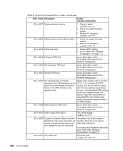
... I/O type set incorrectly 1011 8A00 A different I /O type to service processor in time 1011 9102 Permanent address assignment failed Action/ Possible Failing FRU 1. Check cabling 2. Check for system firmware update. 2. Check for system firmware update. 2. Error Code to 85. Check the internal SPCN cables in configuration table 1011 9101 SPCN failed to respond to 85. See Power Control Network Utilities Menu on page 389. 3. Call service support. 1. See Power Control Network Utilities Menu on page 389. Set the I /O backplane Location...
... I/O type set incorrectly 1011 8A00 A different I /O type to service processor in time 1011 9102 Permanent address assignment failed Action/ Possible Failing FRU 1. Check cabling 2. Check for system firmware update. 2. Check for system firmware update. 2. Error Code to 85. Check the internal SPCN cables in configuration table 1011 9101 SPCN failed to respond to 85. See Power Control Network Utilities Menu on page 389. 3. Call service support. 1. See Power Control Network Utilities Menu on page 389. Set the I /O backplane Location...
Service Guide
Page 224
... the system firmware SMS utilities, the operating system, PCI adapter ROM code or utility, or an operator (via the open firmware script editing command nvedit). The problem can be caused either by a SCSI adapter, whose SCSI bus ID has been changed from the SMS menu(s). 1) Verify the list of a command line within the nvram configuration variable "nvramrc" (script) resulted in the system. If the problem persists, boot the operating system...
... the system firmware SMS utilities, the operating system, PCI adapter ROM code or utility, or an operator (via the open firmware script editing command nvedit). The problem can be caused either by a SCSI adapter, whose SCSI bus ID has been changed from the SMS menu(s). 1) Verify the list of a command line within the nvram configuration variable "nvramrc" (script) resulted in the system. If the problem persists, boot the operating system...
Service Guide
Page 376
... configuration. If the problem persists, check the error logs for instructions on reprogramming the machine type, model, and system serial number in the VPD module on the new operator panel. Go to recover operations. B1xx 4647 The machine type and model Replace the operator panel, location: reported by the service processor. B1xx 4648 CEC backplane VPD failure Ignore all location codes. Information only. Go to MAP 1540 and run CEC minimum configuration. leave operator panel. B1xx 4649 Power supply VPD failure CEC power supply Location...
... configuration. If the problem persists, check the error logs for instructions on reprogramming the machine type, model, and system serial number in the VPD module on the new operator panel. Go to recover operations. B1xx 4647 The machine type and model Replace the operator panel, location: reported by the service processor. B1xx 4648 CEC backplane VPD failure Ignore all location codes. Information only. Go to MAP 1540 and run CEC minimum configuration. leave operator panel. B1xx 4649 Power supply VPD failure CEC power supply Location...

Service Guide
Page 531
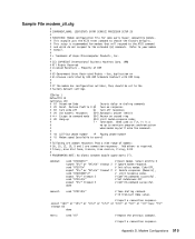
... CallDelay 120 # AT Attention Code , Inserts delay in dialing commands # Z Reset to factory defaults Q0 Turn on responses # E0 Turn echo off Q1 Turn off responses # V0 Use numeric responses S0=0 Automatic answer inhibit # +++ Escape to the # factory default settings. Modem Configurations 513 Property of Hayes Microcomputer Products, Inc. # # (C) COPYRIGHT International Business Machines Corp. 1996 # All Rights Reserved # Licensed Materials - connect: send "ATDT%N\r" # Tone dialing...
... CallDelay 120 # AT Attention Code , Inserts delay in dialing commands # Z Reset to factory defaults Q0 Turn on responses # E0 Turn echo off Q1 Turn off responses # V0 Use numeric responses S0=0 Automatic answer inhibit # +++ Escape to the # factory default settings. Modem Configurations 513 Property of Hayes Microcomputer Products, Inc. # # (C) COPYRIGHT International Business Machines Corp. 1996 # All Rights Reserved # Licensed Materials - connect: send "ATDT%N\r" # Tone dialing...
Service Guide
Page 533
... "A/" # Repeat the previous command. # Expect a connection response. Property of Hayes Microcomputer Products, Inc. # # (C) COPYRIGHT International Business Machines Corp. 1996 # All Rights Reserved # Licensed Materials - Restore Profile 0 Q0 Turn on responses # E0 Turn echo off Q1 Turn off responses # V0 Use numeric responses S0=0 Automatic answer inhibit # +++ Escape to the # factory default settings. Modem Configurations 515 When used as required. # 7=busy; 6=no dial tone...
... "A/" # Repeat the previous command. # Expect a connection response. Property of Hayes Microcomputer Products, Inc. # # (C) COPYRIGHT International Business Machines Corp. 1996 # All Rights Reserved # Licensed Materials - Restore Profile 0 Q0 Turn on responses # E0 Turn echo off Q1 Turn off responses # V0 Use numeric responses S0=0 Automatic answer inhibit # +++ Escape to the # factory default settings. Modem Configurations 515 When used as required. # 7=busy; 6=no dial tone...

Service Guide
Page 550
...-way processor card memory DIMM locations 22 online diagnostics 367 online publications xvii open firmware, entering 7 operating system documentation, AIX 384, 422 operator panel error codes 168 operator panel removal 465 overview diagnostics 69 hot-pluggable PCI adapter 438 P parts 471 CEC drawer 472, 475 CEC drawer internal cables 481 external cables 487 I/O drawer 477, 479 keyboard 488, 490 primary I/O drawer internal cables 483 secondary I/O drawer internal cables 485 PCI adapter removal 431 board locations 19 slot LED definitions 430 phases, ipl 137 physical location codes 32, 36...
...-way processor card memory DIMM locations 22 online diagnostics 367 online publications xvii open firmware, entering 7 operating system documentation, AIX 384, 422 operator panel error codes 168 operator panel removal 465 overview diagnostics 69 hot-pluggable PCI adapter 438 P parts 471 CEC drawer 472, 475 CEC drawer internal cables 481 external cables 487 I/O drawer 477, 479 keyboard 488, 490 primary I/O drawer internal cables 483 secondary I/O drawer internal cables 485 PCI adapter removal 431 board locations 19 slot LED definitions 430 phases, ipl 137 physical location codes 32, 36...
Service Guide
Page 551
... setup menu 376 passwords 375 Index 533 POST keys (continued) numeric 8 key 7 power cables 66 power control network utilities menu 389 power MAP 69, 89 power supply fan removal 454 removal 454 test switch 457 Power-On Self-Test 6 powering on and off 4, 429 preface xvii primary console 508 primary I/O drawer cable diagram 55 cable diagram 55 primary I/O drawer operator panel locations 23 privileged user menus 372 problem determination generated error codes 364 problem determination MAP 69, 84 processor card 443 processor configuration/deconfiguration menu 383 processor/memory configure...
... setup menu 376 passwords 375 Index 533 POST keys (continued) numeric 8 key 7 power cables 66 power control network utilities menu 389 power MAP 69, 89 power supply fan removal 454 removal 454 test switch 457 Power-On Self-Test 6 powering on and off 4, 429 preface xvii primary console 508 primary I/O drawer cable diagram 55 cable diagram 55 primary I/O drawer operator panel locations 23 privileged user menus 372 problem determination generated error codes 364 problem determination MAP 69, 84 processor card 443 processor configuration/deconfiguration menu 383 processor/memory configure...
Service Guide
Page 552
... rear view 18 system unit 8 system diagnostics, loading 367 system firmware update messages 354 system firmware updates 401 system information menu 382 534 Service Guide system management services 415 display error log 417 multiboot 422 OK prompt 425 password utilities 416 remote initial program load setup 417 SCSI utilities 421 select console 421 select language 425 system memory 26 system power-on methods 398 system specifications 58 system unit locations 8 system, powering on...
... rear view 18 system unit 8 system diagnostics, loading 367 system firmware update messages 354 system firmware updates 401 system information menu 382 534 Service Guide system management services 415 display error log 417 multiboot 422 OK prompt 425 password utilities 416 remote initial program load setup 417 SCSI utilities 421 select console 421 select language 425 system memory 26 system power-on methods 398 system specifications 58 system unit locations 8 system, powering on...


