
Maintenance Manual
Page 46
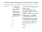
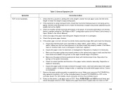
... Level Support. 19. Power on the printer in download mode and load flash memory (page 238). 18. Message List Explanation Corrective Action Non-error status message. 11. Clear NVRAM (page 237). 14. Non-error status message. Run a print test and observe how the paper feeds. Download and install the latest code from IBM First (page 231). 17. If you encounter loading problems, go to DISABLE. At the operator panel, set the paper motion detector (PMD) to the print position. If the problem reappears, replace the paper detector switch assembly and set the paper...
... Level Support. 19. Power on the printer in download mode and load flash memory (page 238). 18. Message List Explanation Corrective Action Non-error status message. 11. Clear NVRAM (page 237). 14. Non-error status message. Run a print test and observe how the paper feeds. Download and install the latest code from IBM First (page 231). 17. If you encounter loading problems, go to DISABLE. At the operator panel, set the paper motion detector (PMD) to the print position. If the problem reappears, replace the paper detector switch assembly and set the paper...
Maintenance Manual
Page 51
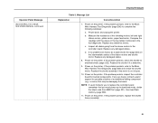
Remove any cable that an over-current condition exists. Check continuity of its travel. 2. Do the following: 7. Clear NVRAM (page 237). 9. Plug in download mode and load flash memory (page 238). 51 Download and install the latest code from the controller board, stacker assembly, and the stacker operator panel. Power on . Adjust the stacker rails if they are bad. 1. Disconnect stacker cables from IBM First (page 231). 10. Power off and unplug the printer. This...
Remove any cable that an over-current condition exists. Check continuity of its travel. 2. Do the following: 7. Clear NVRAM (page 237). 9. Plug in download mode and load flash memory (page 238). 51 Download and install the latest code from the controller board, stacker assembly, and the stacker operator panel. Power on . Adjust the stacker rails if they are bad. 1. Disconnect stacker cables from IBM First (page 231). 10. Power off and unplug the printer. This...

Maintenance Manual
Page 55
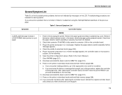
... barrier shield and paper guide (pedestal model). Plug in printer. Download and install the latest code from IBM First (page 231). 10. Load paper. If media with a white or light back. Clear NVRAM (page 237). 9. If the problem reappears, the controller board or microcode is fully seated in its bracket. 4. If message does not clear, go to the User's Manual.) 8. Operator Panel Message 031 END OF FORMS TMEOUT LOAD FORMS Display Messages Table 3. Press STOP. Check that connector P106...
... barrier shield and paper guide (pedestal model). Plug in printer. Download and install the latest code from IBM First (page 231). 10. Load paper. If media with a white or light back. Clear NVRAM (page 237). 9. If the problem reappears, the controller board or microcode is fully seated in its bracket. 4. If message does not clear, go to the User's Manual.) 8. Operator Panel Message 031 END OF FORMS TMEOUT LOAD FORMS Display Messages Table 3. Press STOP. Check that connector P106...

Maintenance Manual
Page 58
... to the User's Manual.) 13. At the operator panel, set the paper motion detector (PMD) to the appropriate error code for resolution. If the problem reappears, the controller board or microcode is suspect. Save the printer configuration values. (Refer to the next step. 16. a. Download and install the latest code from IBM First (page 231). 15. Power on the printer in download mode and load flash memory (page 238). 18. Load paper. b. Chapter 1 Troubleshooting Display Messages Operator Panel Message 032 FORMS JAMMED TIMEOUT CLEAR AND...
... to the User's Manual.) 13. At the operator panel, set the paper motion detector (PMD) to the appropriate error code for resolution. If the problem reappears, the controller board or microcode is suspect. Save the printer configuration values. (Refer to the next step. 16. a. Download and install the latest code from IBM First (page 231). 15. Power on the printer in download mode and load flash memory (page 238). 18. Load paper. b. Chapter 1 Troubleshooting Display Messages Operator Panel Message 032 FORMS JAMMED TIMEOUT CLEAR AND...

Maintenance Manual
Page 65
... check, contact your DDS and Second Level Support. 16. Message List Explanation Corrective Action Non-error status message. 8. Do the following: 9. Clear NVRAM (page 237). 11. Download and install the latest code from IBM First (page 231). 14. Power on the printer in download mode and load flash memory (page 238). 15. If you to the appropriate error code for any binding. If you encounter the failure or message that brought you encounter loading problems, go to this test, replace...
... check, contact your DDS and Second Level Support. 16. Message List Explanation Corrective Action Non-error status message. 8. Do the following: 9. Clear NVRAM (page 237). 11. Download and install the latest code from IBM First (page 231). 14. Power on the printer in download mode and load flash memory (page 238). 15. If you to the appropriate error code for any binding. If you encounter the failure or message that brought you encounter loading problems, go to this test, replace...

Maintenance Manual
Page 66
... fan cables are unobstructed. Power on the printer in such an environment, relocate it on the printer in download mode and load flash memory (page 238). Clear NVRAM (page 237). 8. Inspect printer environment for items blocking the cabinet exhaust vents. Chapter 1 Troubleshooting Display Messages Operator Panel Message 060 PRINTER HOT SEE USERS MANUAL Table 3. Install the paper guide assembly or pedestal top cover. Remove the shuttle cover and Check the shuttle for resolution. a. After replacing the controller board, DO NOT make the printer...
... fan cables are unobstructed. Power on the printer in such an environment, relocate it on the printer in download mode and load flash memory (page 238). Clear NVRAM (page 237). 8. Inspect printer environment for items blocking the cabinet exhaust vents. Chapter 1 Troubleshooting Display Messages Operator Panel Message 060 PRINTER HOT SEE USERS MANUAL Table 3. Install the paper guide assembly or pedestal top cover. Remove the shuttle cover and Check the shuttle for resolution. a. After replacing the controller board, DO NOT make the printer...

Maintenance Manual
Page 76
... encounter the failure after replacing the controller board, reinstall the original controller board and contact your DDS and Second Level Support. 1. Power on the controller board. Check the error log for the printer model you will return for any signs of the 084 error. 3. Before handling circuit boards, put on page 252. Display Messages Operator Panel Message 083 INTAKE FAN CHECK * SEE USERS MANUAL (continued) 084 POWER 48V CHECK * SEE USERS MANUAL Table 3. If it...
... encounter the failure after replacing the controller board, reinstall the original controller board and contact your DDS and Second Level Support. 1. Power on the controller board. Check the error log for the printer model you will return for any signs of the 084 error. 3. Before handling circuit boards, put on page 252. Display Messages Operator Panel Message 083 INTAKE FAN CHECK * SEE USERS MANUAL (continued) 084 POWER 48V CHECK * SEE USERS MANUAL Table 3. If it...
Maintenance Manual
Page 84
... Harness Test Diagnostic (page 256) and check the shuttle motor. Replace any are found , contact Level 2 support for possible isolation of the ribbon motors and shuttle motor. Inspect all cables going from IBM First (page 231), then load flash memory (page 238). 11. Power on the printer. If the problem persists, inspect the controller board for electrical shorts (page 252). b. Power down and unplug the printer. Operator Panel Message 086 CONTROL 15V CHECK SEE USERS MANUAL (continued) Display Messages...
... Harness Test Diagnostic (page 256) and check the shuttle motor. Replace any are found , contact Level 2 support for possible isolation of the ribbon motors and shuttle motor. Inspect all cables going from IBM First (page 231), then load flash memory (page 238). 11. Power on the printer. If the problem persists, inspect the controller board for electrical shorts (page 252). b. Power down and unplug the printer. Operator Panel Message 086 CONTROL 15V CHECK SEE USERS MANUAL (continued) Display Messages...

Maintenance Manual
Page 104
... controller board and contact your DDS and Second Level Support. 104 If you to the appropriate error code for electrical shorts (page 252). 5. If the message appears, power off and unplug the printer. Remove the paper guide assembly or pedestal top cover. Check the shuttle for resolution. Do the following: 6. Download and install the latest code from IBM First (page 231). 9. Run the print job again. Replace as necessary. (See the Cable Shorts Test...
... controller board and contact your DDS and Second Level Support. 104 If you to the appropriate error code for electrical shorts (page 252). 5. If the message appears, power off and unplug the printer. Remove the paper guide assembly or pedestal top cover. Check the shuttle for resolution. Do the following: 6. Download and install the latest code from IBM First (page 231). 9. Run the print job again. Replace as necessary. (See the Cable Shorts Test...

Maintenance Manual
Page 106
... the print job again. Replace as needed. (Refer to the appropriate error code for shorts (page 252). 6. Power on the controller board. 1. Run the print job again. Make sure the MPU cable, the hammer bank logic cable, and the hammer bank power cable are fully seated on page 254.) 5. Do the following: 8. a. Firmware error on the printer in the printer. 3. b. Operator Panel Message 125 PAP FIFO UNDERFLOW * SEE USERS MANUAL Display Messages Table 3. If the problem reappears, the controller board...
... the print job again. Replace as needed. (Refer to the appropriate error code for shorts (page 252). 6. Power on the controller board. 1. Run the print job again. Make sure the MPU cable, the hammer bank logic cable, and the hammer bank power cable are fully seated on page 254.) 5. Do the following: 8. a. Firmware error on the printer in the printer. 3. b. Operator Panel Message 125 PAP FIFO UNDERFLOW * SEE USERS MANUAL Display Messages Table 3. If the problem reappears, the controller board...

Maintenance Manual
Page 161
... connected. 1. After replacing the controller board, DO NOT make the printer READY, but proceed immediately to the appropriate error code for electrical shorts (page 252). 2. failed the current test at power-up. Cycle power. Power on the printer in download mode and load flash memory (page 238). 10. Display Messages Table 3. Check that brought you to the User's Manual.) 5. Power on the printer in download mode and load flash memory (page 238). Message List Explanation Corrective Action Hammer coil(s) number #, #, etc. a. Power on the printer. Record the message...
... connected. 1. After replacing the controller board, DO NOT make the printer READY, but proceed immediately to the appropriate error code for electrical shorts (page 252). 2. failed the current test at power-up. Cycle power. Power on the printer in download mode and load flash memory (page 238). 10. Display Messages Table 3. Check that brought you to the User's Manual.) 5. Power on the printer in download mode and load flash memory (page 238). Message List Explanation Corrective Action Hammer coil(s) number #, #, etc. a. Power on the printer. Record the message...
Maintenance Manual
Page 176
... . Remove the paper guide assembly or pedestal top cover. Plug in Table 5, troubleshoot using the Half-Split Method described on the printer in download mode and load flash memory (page 238). Check the shuttle for resolution. If either message appears. 4. Power on the previous page. If you encounter the failure after replacing the controller board, reinstall the original controller board and contact your DDS and Second Level Support. 176 Download and install the latest code...
... . Remove the paper guide assembly or pedestal top cover. Plug in Table 5, troubleshoot using the Half-Split Method described on the printer in download mode and load flash memory (page 238). Check the shuttle for resolution. If either message appears. 4. Power on the previous page. If you encounter the failure after replacing the controller board, reinstall the original controller board and contact your DDS and Second Level Support. 176 Download and install the latest code...

Maintenance Manual
Page 204
Remove the paper guide assembly or pedestal top cover. Check continuity of CPI, LPI, print quality, forms length, and width. 2. Replace the operator panel cable assembly if it on. Check the shuttle for the proper values of the operator panel cable assembly. Plug in download mode and load flash memory (page 238). 11. Run a self test. If the self test does not run , replace the operator panel assembly. 3. Save the printer configuration values. (Refer to the appropriate error code for...
Remove the paper guide assembly or pedestal top cover. Check continuity of CPI, LPI, print quality, forms length, and width. 2. Replace the operator panel cable assembly if it on. Check the shuttle for the proper values of the operator panel cable assembly. Plug in download mode and load flash memory (page 238). 11. Run a self test. If the self test does not run , replace the operator panel assembly. 3. Save the printer configuration values. (Refer to the appropriate error code for...
Maintenance Manual
Page 206
... tented, consider setting the "Set Platen at BOF" configuration option (in the groove on the controller board. d. Correct as necessary. 7. Remove the paper guide assembly or pedestal top cover. Power on the controller board. 8. Check that the customer is not being used . Make sure the paper guides are seated in the Printer Control menu) to Open. (Refer to match the size paper used . 2. Load paper and set too tightly. General Symptom List Corrective Action 1. Set the forms...
... tented, consider setting the "Set Platen at BOF" configuration option (in the groove on the controller board. d. Correct as necessary. 7. Remove the paper guide assembly or pedestal top cover. Power on the controller board. 8. Check that the customer is not being used . Make sure the paper guides are seated in the Printer Control menu) to Open. (Refer to match the size paper used . 2. Load paper and set too tightly. General Symptom List Corrective Action 1. Set the forms...
Maintenance Manual
Page 216
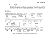
... upgrades adapter settings. (On printers with external NIC adapter.) 3 to next page Done ENTER ENTER Printer reboots with external NIC adapter.) Figure 7. You will use ; PRINTER MGMT E-NET TO DEFAULT ENTER (On printers with CT installed) ENABLE* DISABLE Demo Count 1 * 2 5 10 Continuous PRINTER MGMT Debug Port Cfg PRINTER MGMT Serial PRINTER MGMT Clear Password PRINTER MGMT Reboot w/Factory PRINTER MGMT MANAGER PORT NO. These are called "Customer Engineer Tests" (CE Tests) because they are for use as maintenance...
... upgrades adapter settings. (On printers with external NIC adapter.) 3 to next page Done ENTER ENTER Printer reboots with external NIC adapter.) Figure 7. You will use ; PRINTER MGMT E-NET TO DEFAULT ENTER (On printers with CT installed) ENABLE* DISABLE Demo Count 1 * 2 5 10 Continuous PRINTER MGMT Debug Port Cfg PRINTER MGMT Serial PRINTER MGMT Clear Password PRINTER MGMT Reboot w/Factory PRINTER MGMT MANAGER PORT NO. These are called "Customer Engineer Tests" (CE Tests) because they are for use as maintenance...

Maintenance Manual
Page 226
...; Installed Memory Displays the amount of the printer statistics are set to zero at the factory after burn-in testing. The range is 0 to 30,000 hours. 226 they do not reset when you power off the printer. To exit the configuration menus and return to these figures for preventive maintenance purposes. Printing Time The cumulative time in hours that the printer has been powered on Time The...
...; Installed Memory Displays the amount of the printer statistics are set to zero at the factory after burn-in testing. The range is 0 to 30,000 hours. 226 they do not reset when you power off the printer. To exit the configuration menus and return to these figures for preventive maintenance purposes. Printing Time The cumulative time in hours that the printer has been powered on Time The...

Maintenance Manual
Page 231
... the previous menu. In this section. At the default settings, when ribbon life reaches 2% the message changes to accomodate individual requirements. The operator panel status lamp flashes, but the printer continues to accept new print jobs until ribbon life reaches 0%, at the factory, and the system functions without intervention as long as a new ribbon installation. NOTE: The labels attached to each ribbon spool on opposite sides, so...
... the previous menu. In this section. At the default settings, when ribbon life reaches 2% the message changes to accomodate individual requirements. The operator panel status lamp flashes, but the printer continues to accept new print jobs until ribbon life reaches 0%, at the factory, and the system functions without intervention as long as a new ribbon installation. NOTE: The labels attached to each ribbon spool on opposite sides, so...

Maintenance Manual
Page 232
... all printer configurations and cannot be set value (density). The second line of the display changes to the character life expectancy of the detected, authorized ribbon installed in effect until it is now the default option. RibbonMinder Operation the selections at BOF Shuttle Timeout Energy Saver Timer OCR Font Density Eject/Restore PTR Setup Option File System Power Stacker 1 Auto Elevator 1 Printer Management Port Top...
... all printer configurations and cannot be set value (density). The second line of the display changes to the character life expectancy of the detected, authorized ribbon installed in effect until it is now the default option. RibbonMinder Operation the selections at BOF Shuttle Timeout Energy Saver Timer OCR Font Density Eject/Restore PTR Setup Option File System Power Stacker 1 Auto Elevator 1 Printer Management Port Top...
Maintenance Manual
Page 250
... cabinet models, open the rear door. Power off the printer. 2. When the printer detects a valid SPX, the operator panel displays: "NEW SPX DETECTED PRESS ENTER" NOTE: If an error message displays, find the message in the Message List in Figure 11. 4. The SPX is not required to enable features such as in Chapter 3 and follow the troubleshooting instructions. 6. Field Kit, SPX, IBM MES, Code V/IGP • P/N 39U2695 - On pedestal models, use disposable...
... cabinet models, open the rear door. Power off the printer. 2. When the printer detects a valid SPX, the operator panel displays: "NEW SPX DETECTED PRESS ENTER" NOTE: If an error message displays, find the message in the Message List in Figure 11. 4. The SPX is not required to enable features such as in Chapter 3 and follow the troubleshooting instructions. 6. Field Kit, SPX, IBM MES, Code V/IGP • P/N 39U2695 - On pedestal models, use disposable...

Maintenance Manual
Page 417
... Paper Detector Switch Assy Paper Detector Switch Assy Screw, Thread Forming, 6-32x.375 (2) Paper Feed Motor Assy, All Except Model v20 Paper Feed Motor Assy, Model v20 6 Ref Motor Pulley, Platen Open, Driver 7 Ref Screw, Hex w/Lock Washer (2) 8 39U2540 Ribbon Guide Cable Assembly, RH 39U2539 Ribbon Guide Cable Assembly, LH 9 54P1453 Platen Open Motor... into card cage Two 6-32x1.75 on botton One 6-32x0.50 on the motor base and torque the mounting screws to 18 inch-pounds (2.03 N•m). Install it on top left Standard switch Black Back forms Model v20 only: Re-use the original...
... Paper Detector Switch Assy Paper Detector Switch Assy Screw, Thread Forming, 6-32x.375 (2) Paper Feed Motor Assy, All Except Model v20 Paper Feed Motor Assy, Model v20 6 Ref Motor Pulley, Platen Open, Driver 7 Ref Screw, Hex w/Lock Washer (2) 8 39U2540 Ribbon Guide Cable Assembly, RH 39U2539 Ribbon Guide Cable Assembly, LH 9 54P1453 Platen Open Motor... into card cage Two 6-32x1.75 on botton One 6-32x0.50 on the motor base and torque the mounting screws to 18 inch-pounds (2.03 N•m). Install it on top left Standard switch Black Back forms Model v20 only: Re-use the original...


