Service Guide
Page 5
... port specifications 15 Machine serial number location 16 Chapter 2. Resolving problems 25 Start problem diagnosis here 25 Preliminary checklist 26 © Copyright IBM Corp. 2004, 2006 iii Configuring the system 17 How to use the touch screen 17 The Setup Utility 18 Usage tips and navigation 18 Starting the Setup Utility 19 Updating the flash BIOS 22 Power interruption during flash BIOS update procedure 22 Repairing the flash BIOS 22 Real-time clock and CMOS 22 Restoring the default CMOS settings 22 Clearing the CMOS settings...
... port specifications 15 Machine serial number location 16 Chapter 2. Resolving problems 25 Start problem diagnosis here 25 Preliminary checklist 26 © Copyright IBM Corp. 2004, 2006 iii Configuring the system 17 How to use the touch screen 17 The Setup Utility 18 Usage tips and navigation 18 Starting the Setup Utility 19 Updating the flash BIOS 22 Power interruption during flash BIOS update procedure 22 Repairing the flash BIOS 22 Real-time clock and CMOS 22 Restoring the default CMOS settings 22 Clearing the CMOS settings...
Service Guide
Page 6
... HDD bracket - removing and replacing 82 Free-standing SurePOS 500 Models 5x3 and 544/564 - removing and replacing 67 System-board battery - removing and replacing 72 PC card blank - removing and replacing 78 Integrated customer display - removing and replacing 52 HDD fan - removing and replacing 48 Display tablet cable - Removing and replacing FRUs for the 5x4 models 31 Diagnostic wrap plugs 31 Chapter 4. | | | | | | iv August 3, 2006 Troubleshooting 27 CMOS recovery 30 Running Diagnostics 30 Using the Service Diskette (for the 5x3 models 30 Using the IBM Diagnostics...
... HDD bracket - removing and replacing 82 Free-standing SurePOS 500 Models 5x3 and 544/564 - removing and replacing 67 System-board battery - removing and replacing 72 PC card blank - removing and replacing 78 Integrated customer display - removing and replacing 52 HDD fan - removing and replacing 48 Display tablet cable - Removing and replacing FRUs for the 5x4 models 31 Diagnostic wrap plugs 31 Chapter 4. | | | | | | iv August 3, 2006 Troubleshooting 27 CMOS recovery 30 Running Diagnostics 30 Using the Service Diskette (for the 5x3 models 30 Using the IBM Diagnostics...
Service Guide
Page 9
.... Setup Utility panels locations 18 12. Example of the Power Management window 21 15. Latch 49 30. Hinge assembly 50 31. Dual video adapter jumper location 63 44. Speaker removal 55 35. Power supply remove/replace 57 38. Cooling duct 64 45. Removing a PC card adapter 75 © Copyright IBM Corp. 2004, 2006 vii Removing side covers 42 23. Removing the MSR 47 28. HDD replacement 51 32. Video card removal 62 43. SurePOS 500 Models 5x3 and 544/564 configuration with keyboard-integration tray 8 5. Free-standing option...
.... Setup Utility panels locations 18 12. Example of the Power Management window 21 15. Latch 49 30. Hinge assembly 50 31. Dual video adapter jumper location 63 44. Speaker removal 55 35. Power supply remove/replace 57 38. Cooling duct 64 45. Removing a PC card adapter 75 © Copyright IBM Corp. 2004, 2006 vii Removing side covers 42 23. Removing the MSR 47 28. HDD replacement 51 32. Video card removal 62 43. SurePOS 500 Models 5x3 and 544/564 configuration with keyboard-integration tray 8 5. Free-standing option...
Service Guide
Page 13
... cash drawer connector pins 186 36. Unit dimensions with 4820 SurePoint Solution 176 18. Keyboard and mouse connector-pin assignments 180 26. RJ-45 connector-pin assignments 181 30. Repair actions for CANPOS keyboard problems 135 12. Trademarks 197 © Copyright IBM Corp. 2004, 2006 xi USB port connector-pin assignments 180 24. USB port connector-pin assignments 180 25. Using the touch screen 17 6. SurePOS 500 Models 5x3 and 544/564 task information 25 7. Ethernet connector-pin assignments...
... cash drawer connector pins 186 36. Unit dimensions with 4820 SurePoint Solution 176 18. Keyboard and mouse connector-pin assignments 180 26. RJ-45 connector-pin assignments 181 30. Repair actions for CANPOS keyboard problems 135 12. Trademarks 197 © Copyright IBM Corp. 2004, 2006 xi USB port connector-pin assignments 180 24. USB port connector-pin assignments 180 25. Using the touch screen 17 6. SurePOS 500 Models 5x3 and 544/564 task information 25 7. Ethernet connector-pin assignments...
Service Guide
Page 23
... maintaining the system unit, including parts listings, troubleshooting, and removal and replacement procedures. Related publications The SurePOS 500 Series library consists of this guide This guide is for Models 533, 543, 544, 553, 563, 564, 573, and 5A3, GA27-4330 This guide provides installation and setup information, including option installation procedures and problem determination information. Note: References in maintaining and repairing the IBM SurePOS 500 Series Models 533, 543, 544, 553, 563, 564, 573, and...
... maintaining the system unit, including parts listings, troubleshooting, and removal and replacement procedures. Related publications The SurePOS 500 Series library consists of this guide This guide is for Models 533, 543, 544, 553, 563, 564, 573, and 5A3, GA27-4330 This guide provides installation and setup information, including option installation procedures and problem determination information. Note: References in maintaining and repairing the IBM SurePOS 500 Series Models 533, 543, 544, 553, 563, 564, 573, and...
Service Guide
Page 30
... v Supported memory: 128-MB, 256-MB, 512-MB, and 1-GB memory upgrades, allowing a maximum of the operator display and requires an optional | display adapter feature card. 4 Optional features The following options are present. Information displayed on the SurePOS 500 Models 5x3 and 544/564 operator display is powered by the system unit may be attached (Models 5x3 only). | This display operates independently of 2 GB (two 1-GB DIMMs). Other external VGA devices can be connected to the SurePOS 500 Models 5x3 and 544/564 15-pin video port. | In...
... v Supported memory: 128-MB, 256-MB, 512-MB, and 1-GB memory upgrades, allowing a maximum of the operator display and requires an optional | display adapter feature card. 4 Optional features The following options are present. Information displayed on the SurePOS 500 Models 5x3 and 544/564 operator display is powered by the system unit may be attached (Models 5x3 only). | This display operates independently of 2 GB (two 1-GB DIMMs). Other external VGA devices can be connected to the SurePOS 500 Models 5x3 and 544/564 15-pin video port. | In...
Service Guide
Page 31
... to use a wireless card on Windows-based systems Chapter 1. Note: Remote Program Load (RPL) and power up on LAN or Ring are not supported for SUSE (IRES) Linux (Models 5x3 only) System software includes: v Basic input/output software (BIOS) v Plug and Play BIOS v Power-on self-test (POST) v Configuration/Setup Utility program v Advanced Power Management (APM) (DOS and Linux only) v Advanced Configuration and Power Interface (ACPI)1 v Flash-update utility program | v SurePOS 500 Models 5x3 and 544/564 Diagnostic programs v Device drivers 1. August 3, 2006 Optional...
... to use a wireless card on Windows-based systems Chapter 1. Note: Remote Program Load (RPL) and power up on LAN or Ring are not supported for SUSE (IRES) Linux (Models 5x3 only) System software includes: v Basic input/output software (BIOS) v Plug and Play BIOS v Power-on self-test (POST) v Configuration/Setup Utility program v Advanced Power Management (APM) (DOS and Linux only) v Advanced Configuration and Power Interface (ACPI)1 v Flash-update utility program | v SurePOS 500 Models 5x3 and 544/564 Diagnostic programs v Device drivers 1. August 3, 2006 Optional...
Service Guide
Page 40
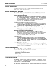
... management programs The SurePOS 500 Models 5x3 and 544/564 supports the following products with the SurePOS 500 Models 5x3 and 544/564. This allows access to reduce power consumption. RDM can be accessed are the BIOS level, processor type, speed, manufacturer, system-board information, and detailed memory information. Power up on LAN This feature enables the system to power on a network. These applications are supported: v Selectable startup sequence v Update POST/BIOS from the network v Ethernet setup v Power up on LAN in the Setup Utility...
... management programs The SurePOS 500 Models 5x3 and 544/564 supports the following products with the SurePOS 500 Models 5x3 and 544/564. This allows access to reduce power consumption. RDM can be accessed are the BIOS level, processor type, speed, manufacturer, system-board information, and detailed memory information. Power up on LAN This feature enables the system to power on a network. These applications are supported: v Selectable startup sequence v Update POST/BIOS from the network v Ethernet setup v Power up on LAN in the Setup Utility...
Service Guide
Page 48
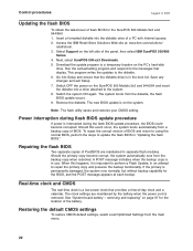
... settings are maintained in the boot list. Restoring the default CMOS settings To restore CMOS default settings, select Load Optimized Settings from the backup copy when rebooted. Next, select SurePOS 500-xx3 Downloads. 5. Control procedures August 3, 2006 Updating the flash BIOS To obtain the latest level of a PC with Internet access. 2. Select Support on the system. The system boots from a backup copy of the panel, then select IBM SurePOS 500/600 Series. 4. The new BIOS update is removed. Note: The flash utility saves and restores your CMOS setting...
... settings are maintained in the boot list. Restoring the default CMOS settings To restore CMOS default settings, select Load Optimized Settings from the backup copy when rebooted. Next, select SurePOS 500-xx3 Downloads. 5. Control procedures August 3, 2006 Updating the flash BIOS To obtain the latest level of a PC with Internet access. 2. Select Support on the system. The system boots from a backup copy of the panel, then select IBM SurePOS 500/600 Series. 4. The new BIOS update is removed. Note: The flash utility saves and restores your CMOS setting...

Service Guide
Page 49
... Clearing the CMOS settings The SurePOS 500 Models 5x3 and 544/564 uses battery-backed CMOS memory to pins 1 and 2. 6. This resets the CMOS. 5. Return the jumper to store system settings. Power ON the system. 7. If the CMOS memory becomes corrupted and the system does not boot, you restart the system after resetting the CMOS, the following these errors, run the Setup Utility and select Load Optimized Defaults. Remove the jumper, which is normally located on pins 1 and 2. (Pin 1 is displayed: CMOS checksum error - This restores...
... Clearing the CMOS settings The SurePOS 500 Models 5x3 and 544/564 uses battery-backed CMOS memory to pins 1 and 2. 6. This resets the CMOS. 5. Return the jumper to store system settings. Power ON the system. 7. If the CMOS memory becomes corrupted and the system does not boot, you restart the system after resetting the CMOS, the following these errors, run the Setup Utility and select Load Optimized Defaults. Remove the jumper, which is normally located on pins 1 and 2. (Pin 1 is displayed: CMOS checksum error - This restores...
Service Guide
Page 51
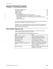
... up a part number. Update the flash BIOS. "The Setup Utility" on page 145. Review service tips. Start problem diagnosis here If you determine the cause of a problem and resolve it. Run the Setup Utility. Appendix A, "Parts catalog," on page 18. | Run diagnostics. Appendix D, "SurePOS 500 Models 5x3 and 544/564 tips," on page 22. Table 6. August 3, 2006 Chapter 3. Chapter 4, "Removing and replacing FRUs for the SurePOS 500 Models 5x3 and 544/564 and peripheral I/O devices. A software error or a hardware failure can cause a problem with...
... up a part number. Update the flash BIOS. "The Setup Utility" on page 145. Review service tips. Start problem diagnosis here If you determine the cause of a problem and resolve it. Run the Setup Utility. Appendix A, "Parts catalog," on page 18. | Run diagnostics. Appendix D, "SurePOS 500 Models 5x3 and 544/564 tips," on page 22. Table 6. August 3, 2006 Chapter 3. Chapter 4, "Removing and replacing FRUs for the SurePOS 500 Models 5x3 and 544/564 and peripheral I/O devices. A software error or a hardware failure can cause a problem with...

Service Guide
Page 53
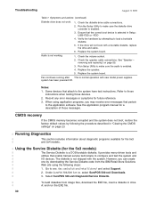
...'s what to the open position. 1. Verify the LED card cable is plugged in an attempt to fix a problem, go to "Clearing the CMOS settings" on page 23 and reset CMOS to find problem symptoms and take the related action. Verify the power cable is ... Replace the system board. Operator display exhibits: Blank screen No cursor displayed Screen is unreadable Other display problems. 1. See "Display tablet - Cash drawer does not open position to "Running | Diagnostics" on page 30...
...'s what to the open position. 1. Verify the LED card cable is plugged in an attempt to fix a problem, go to "Clearing the CMOS settings" on page 23 and reset CMOS to find problem symptoms and take the related action. Verify the power cable is ... Replace the system board. Operator display exhibits: Blank screen No cursor displayed Screen is unreadable Other display problems. 1. See "Display tablet - Cash drawer does not open position to "Running | Diagnostics" on page 30...
Service Guide
Page 55
.... 5. Run the keyboard test. Compact ANPOS keyboard problem solving. 1. Resolving problems 29 Reset to "Running Diagnostics" on page 135 for either side or rear connectors. 2. See "LED card and cable - Check the three-track MSR dip switch settings for CANPOS Keyboard problem solving. Run Setup and check the setting in the MSR serial port. 3. removing and replacing" on page 30. 3. Touch screen not working . 1. Refer to either RS232 or keyboard interface. 2. See "System board - removing and replacing" on them. 5. Replace the LED board. PS...
.... 5. Run the keyboard test. Compact ANPOS keyboard problem solving. 1. Resolving problems 29 Reset to "Running Diagnostics" on page 135 for either side or rear connectors. 2. See "LED card and cable - Check the three-track MSR dip switch settings for CANPOS Keyboard problem solving. Run Setup and check the setting in the MSR serial port. 3. removing and replacing" on page 30. 3. Touch screen not working . 1. Refer to either RS232 or keyboard interface. 2. See "System board - removing and replacing" on them. 5. Replace the LED board. PS...
Service Guide
Page 56
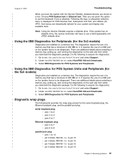
... Series select SurePOS 500-xx3 Downloads. | 3. Check the volume control. 2. See "Speaker - Notes: 1. CMOS recovery If the CMOS memory becomes corrupted and the system does not boot, restore the factory default values by following steps: | 1. The diskette is enabled. 3. Verify the hardware by downloading the Service Diskette code from image files, download the EXE file, insert a diskette in "Clearing the CMOS settings" on page 55. 3. Refer to www.ibm.com/solutions/retail/store/ and select Support...
... Series select SurePOS 500-xx3 Downloads. | 3. Check the volume control. 2. See "Speaker - Notes: 1. CMOS recovery If the CMOS memory becomes corrupted and the system does not boot, restore the factory default values by following steps: | 1. The diskette is enabled. 3. Verify the hardware by downloading the Service Diskette code from image files, download the EXE file, insert a diskette in "Clearing the CMOS settings" on page 55. 3. Refer to www.ibm.com/solutions/retail/store/ and select Support...
Service Guide
Page 57
... 256 MB on a memory key. There are installed on it . Following the logo, a subsystem selection | menu is attached. Under SurePOS 500/600 Series select SurePOS 500-xx3 Downloads. | 3. Choose POS System test or Ethernet test. Go to www.ibm.com/solutions/retail/store/ and select Support. | 2. Select IBM Diagnostics for POS Systems and Peripherals | Using the IBM Diagnostics for POS System Units and Peripherals (for | the 5x4 models) | Diagnostics are additional details about selecting a | memory key, setting...
... 256 MB on a memory key. There are installed on it . Following the logo, a subsystem selection | menu is attached. Under SurePOS 500/600 Series select SurePOS 500-xx3 Downloads. | 3. Choose POS System test or Ethernet test. Go to www.ibm.com/solutions/retail/store/ and select Support. | 2. Select IBM Diagnostics for POS Systems and Peripherals | Using the IBM Diagnostics for POS System Units and Peripherals (for | the 5x4 models) | Diagnostics are additional details about selecting a | memory key, setting...
Service Guide
Page 59
... options - removing from the base 82 Non-keyboard integration tray - removing and replacing 55 Power supply - removing and replacing 80 Mounting foot - Removing and replacing FRUs for counter mount systems . . . . 59 Connecting cables to the side access panel 59 Connecting cables to the rear connector panel 59 Dual-video adapter - removing and replacing 37 Rear cover - removing and replacing 42 Side I /O EMC shield - removing and replacing 52 LED card and cable - removing and replacing 67 System-board battery - removing and replacing 74 Rear connector panel (tailgate...
... options - removing from the base 82 Non-keyboard integration tray - removing and replacing 55 Power supply - removing and replacing 80 Mounting foot - Removing and replacing FRUs for counter mount systems . . . . 59 Connecting cables to the side access panel 59 Connecting cables to the rear connector panel 59 Dual-video adapter - removing and replacing 37 Rear cover - removing and replacing 42 Side I /O EMC shield - removing and replacing 52 LED card and cable - removing and replacing 67 System-board battery - removing and replacing 74 Rear connector panel (tailgate...
Service Guide
Page 249
... option 9 © Copyright IBM Corp. 2004, 2006 checklist, problem diagnosis 26 clearing CMOS settings 23 system password 21 clock, real-time 22 CMOS RAM 22 recovery 30 settings clearing 23 restoring defaults 22 standard features 20 coin roll cutter, removing and replacing 111 CompactFlash removing and replacing 51 compatible products 14 configuration, main window 19 configuring hard disk time-out 21 I/O devices 21 power savings 21 video time-out 21 configuring the system 17 connector 15-pin serial pin assignments 183 9-pin serial pin...
... option 9 © Copyright IBM Corp. 2004, 2006 checklist, problem diagnosis 26 clearing CMOS settings 23 system password 21 clock, real-time 22 CMOS RAM 22 recovery 30 settings clearing 23 restoring defaults 22 standard features 20 coin roll cutter, removing and replacing 111 CompactFlash removing and replacing 51 compatible products 14 configuration, main window 19 configuring hard disk time-out 21 I/O devices 21 power savings 21 video time-out 21 configuring the system 17 connector 15-pin serial pin assignments 183 9-pin serial pin...
Service Guide
Page 250
... connectors 179 External video connector pin assignments 185 F fansink removing and replacing 69 features i, 2 accessibility 198 dual display feature 4 optional 4 standard 3 system management 14 system software 5 flash BIOS update procedure 22 power interruption 22 flash, update 22 foot, mounting removing and replacing 81 free standing mounting option 6 removing and replacing 82 FRUs system board 148 wall mount 150 full size cash drawer removing and replacing 105 August 3, 2006 H handling static-sensitive devices xx, 34 hard disk time-out configuration 21 HDD cables 52 HDD cover 36 HDD fan...
... connectors 179 External video connector pin assignments 185 F fansink removing and replacing 69 features i, 2 accessibility 198 dual display feature 4 optional 4 standard 3 system management 14 system software 5 flash BIOS update procedure 22 power interruption 22 flash, update 22 foot, mounting removing and replacing 81 free standing mounting option 6 removing and replacing 82 FRUs system board 148 wall mount 150 full size cash drawer removing and replacing 105 August 3, 2006 H handling static-sensitive devices xx, 34 hard disk time-out configuration 21 HDD cables 52 HDD cover 36 HDD fan...
Service Guide
Page 253
...100 y-cable, keyboard integration tray 93 replacement parts 145 replacing FRUs 34 requirements power 178 resolving problems 25 restoring default CMOS settings 22 RJ-45 connector pin assignments 181 rollers removing and replacing 110 running diagnostics 30 running setup utility 18 S safety laser xiii notice translations xiii notices xiii safety information xiii, 199 safety notices 201 security clip, removing and replacing 112 serial number location 16 serial number, location 20 serial port 15 Service Diskette 30 service tools 189 setting changing, clearing password 21 clearing CMOS 23 restoring...
...100 y-cable, keyboard integration tray 93 replacement parts 145 replacing FRUs 34 requirements power 178 resolving problems 25 restoring default CMOS settings 22 RJ-45 connector pin assignments 181 rollers removing and replacing 110 running diagnostics 30 running setup utility 18 S safety laser xiii notice translations xiii notices xiii safety information xiii, 199 safety notices 201 security clip, removing and replacing 112 serial number location 16 serial number, location 20 serial port 15 Service Diskette 30 service tools 189 setting changing, clearing password 21 clearing CMOS 23 restoring...
Service Guide
Page 254
... Power Management window 21 starting the 19 using 18 side access panel 59 side covers, removing and replacing 42 size of unit 172 skills needed to install, configure, and administer this product xxi slide latches 108 software options 5 speaker 55 speaker panel 36 speaker, connector pin assignments 179 specifications height 170 weight 170 standard features 3 start problem diagnosis here 25 starting the Setup Utility 19 static-sensitive devices, handling xx, 34 summary of changes xxii summary window, configuration 19 support xxii, 30 support...
... Power Management window 21 starting the 19 using 18 side access panel 59 side covers, removing and replacing 42 size of unit 172 skills needed to install, configure, and administer this product xxi slide latches 108 software options 5 speaker 55 speaker panel 36 speaker, connector pin assignments 179 specifications height 170 weight 170 standard features 3 start problem diagnosis here 25 starting the Setup Utility 19 static-sensitive devices, handling xx, 34 summary of changes xxii summary window, configuration 19 support xxii, 30 support...


