
Installation Guide
Page 4
... Model x4x of the IBM 4810/4910 Point of Retail Store Solutions documentation are available on page 57. IBM welcomes your comments to the following address: IBM Corporation Retail Store Solutions Information Development, Department ZBDA PO Box 12195 Research Triangle Park, North Carolina, 27709 U.S.A. Current versions of Sale terminal and to you supply in any way it supports, be sure to read...
... Model x4x of the IBM 4810/4910 Point of Retail Store Solutions documentation are available on page 57. IBM welcomes your comments to the following address: IBM Corporation Retail Store Solutions Information Development, Department ZBDA PO Box 12195 Research Triangle Park, North Carolina, 27709 U.S.A. Current versions of Sale terminal and to you supply in any way it supports, be sure to read...
Installation Guide
Page 5
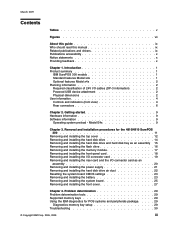
... Contents Tables v Figures vii About this guide ix Who should read this manual ix Related publications and drivers ix Publications accessibility x Notice statements x Providing feedback x Chapter 1. Removal and installation procedures for POS systems and peripherals package. . . . . 29 Diagnostics memory key setup 29 Troubleshooting 30 © Copyright IBM Corp. 2005, 2009 iii Problem determination 29 Problem determination tools 29 Supported memory keys 29 Using the IBM diagnostics for the 4810/4910 SurePOS...
... Contents Tables v Figures vii About this guide ix Who should read this manual ix Related publications and drivers ix Publications accessibility x Notice statements x Providing feedback x Chapter 1. Removal and installation procedures for POS systems and peripherals package. . . . . 29 Diagnostics memory key setup 29 Troubleshooting 30 © Copyright IBM Corp. 2005, 2009 iii Problem determination 29 Problem determination tools 29 Supported memory keys 29 Using the IBM diagnostics for the 4810/4910 SurePOS...

Installation Guide
Page 6
... information 62 Cable ferrite requirement 62 Electrostatic Discharge (ESD 62 Product Recycling and disposal 63 Battery return program 64 For Taiwan 64 For the European Union 65 For California 65 Flat panel displays 66 Monitors and workstations 66 Trademarks 66 Index 67 Part number index 69 iv SurePOS Installation and Service Parts catalog 37 Assembly 1: Field-replaceable units 38 Chapter 6.
... information 62 Cable ferrite requirement 62 Electrostatic Discharge (ESD 62 Product Recycling and disposal 63 Battery return program 64 For Taiwan 64 For the European Union 65 For California 65 Flat panel displays 66 Monitors and workstations 66 Trademarks 66 Index 67 Part number index 69 iv SurePOS Installation and Service Parts catalog 37 Assembly 1: Field-replaceable units 38 Chapter 6.
Installation Guide
Page 9
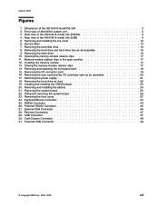
.... Opening the memory-module retainer clips 17 11. Installing the memory module 17 13. Removing the riser card and the I /O connector card 19 16. Removing and installing the battery 24 21. Removing the hard drive air duct 22 19. Powered RS232 Connector 45 27. Powered USB Connector 49 © Copyright IBM Corp. 2005, 2009 vii Rear view of the 4810/4910 model x4x (RS232 6 4. USB Connector 47 30. Closing...
.... Opening the memory-module retainer clips 17 11. Installing the memory module 17 13. Removing the riser card and the I /O connector card 19 16. Removing and installing the battery 24 21. Removing the hard drive air duct 22 19. Powered RS232 Connector 45 27. Powered USB Connector 49 © Copyright IBM Corp. 2005, 2009 vii Rear view of the 4810/4910 model x4x (RS232 6 4. USB Connector 47 30. Closing...
Installation Guide
Page 11
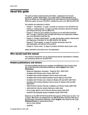
... SurePoint Solution Planning, Installation and Service Guide, GA27-4231 v 4820 SurePoint Solution System Reference, SA27-4249 v Point of Sale Options and I/O Devices Service Guide, GC30-9737 v SurePOS 300 Operating System Installation Guide, GA27-4360 Model x4x of the IBM 4810/4910 SurePOS 300 requires UPOS drivers at level 1.9.6 or higher. v Chapter 5, "Parts catalog," on page 37 provides information about power cords. v Chapter 3, "Removal and installation procedures for the...
... SurePoint Solution Planning, Installation and Service Guide, GA27-4231 v 4820 SurePoint Solution System Reference, SA27-4249 v Point of Sale Options and I/O Devices Service Guide, GC30-9737 v SurePOS 300 Operating System Installation Guide, GA27-4360 Model x4x of the IBM 4810/4910 SurePOS 300 requires UPOS drivers at level 1.9.6 or higher. v Chapter 5, "Parts catalog," on page 37 provides information about power cords. v Chapter 3, "Removal and installation procedures for the...

Installation Guide
Page 12
.../support. Box 12195 Research Triangle Park, North Carolina 27709 USA Be sure to include the name and form number of this guide are accessibility enabled. Danger: These statements indicate situations that might help you . To provide feedback: v Go to the specific location of a potentially hazardous procedure step or situation. v You can be potentially hazardous to programs, devices, or data...
.../support. Box 12195 Research Triangle Park, North Carolina 27709 USA Be sure to include the name and form number of this guide are accessibility enabled. Danger: These statements indicate situations that might help you . To provide feedback: v Go to the specific location of a potentially hazardous procedure step or situation. v You can be potentially hazardous to programs, devices, or data...
Installation Guide
Page 13
About this document, there might be minor technical updates. March 2009 Between major revisions of this document is available on the Retail Store Solutions Web site at www.ibm.com/solutions/retail/store/support/publications/. The latest version of this guide xi
About this document, there might be minor technical updates. March 2009 Between major revisions of this document is available on the Retail Store Solutions Web site at www.ibm.com/solutions/retail/store/support/publications/. The latest version of this guide xi
Installation Guide
Page 15
... Accelerator 900 © Copyright IBM Corp. 2005, 2009 1 Table 1. Summary of features Type of Sale terminal. microphone v One - March 2009 Chapter 1. line in some countries) v 4910-E4D 4810-E40 base system unit bundled with a 4610 Dual Station Printer and Non-Touch Monitor (in v One - Three 5V/12V powered RS232 (nine pin female D-shell) v USB Connector Card installed - Designed specifically for 400 MHz DDR2 RAM...
... Accelerator 900 © Copyright IBM Corp. 2005, 2009 1 Table 1. Summary of features Type of Sale terminal. microphone v One - March 2009 Chapter 1. line in some countries) v 4910-E4D 4810-E40 base system unit bundled with a 4610 Dual Station Printer and Non-Touch Monitor (in v One - Three 5V/12V powered RS232 (nine pin female D-shell) v USB Connector Card installed - Designed specifically for 400 MHz DDR2 RAM...
Installation Guide
Page 16
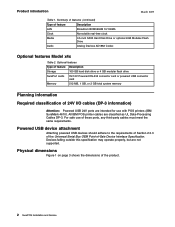
... Table 1. All IBM POS printer cables are not supported. For safe use of 24V I/O cables (DP-3 information) Attention: Powered USB 24V ports are intended for use with POS printers (IBM SureMark 4610). Optional features Type of feature Description Storage 160 GB hard disk drive or 4 GB modular flash drive SurePort cards 5V/12V Powered RS-232 connector card or powered USB connector card Memory 512 MB, 1 GB, or 2 GB total system memory...
... Table 1. All IBM POS printer cables are not supported. For safe use of 24V I/O cables (DP-3 information) Attention: Powered USB 24V ports are intended for use with POS printers (IBM SureMark 4610). Optional features Type of feature Description Storage 160 GB hard disk drive or 4 GB modular flash drive SurePort cards 5V/12V Powered RS-232 connector card or powered USB connector card Memory 512 MB, 1 GB, or 2 GB total system memory...

Installation Guide
Page 18
...; to 140° F) A fan contained in .) minimum clearance. Combined, the wake-enabled USB ports 1 and 2, the 12V USB port, and the PS/2 keyboard and mouse ports can only support a maximum 5V load of the 4810/4910 system unit. 4 SurePOS Installation and Service E Cash Drawer Keyboard and Mouse Port Voltage Ratings 5V 12V 5V 12V 24V 24V 5V Maximum Current 1.0A 1.0A 0.5A...
...; to 140° F) A fan contained in .) minimum clearance. Combined, the wake-enabled USB ports 1 and 2, the 12V USB port, and the PS/2 keyboard and mouse ports can only support a maximum 5V load of the 4810/4910 system unit. 4 SurePOS Installation and Service E Cash Drawer Keyboard and Mouse Port Voltage Ratings 5V 12V 5V 12V 24V 24V 5V Maximum Current 1.0A 1.0A 0.5A...

Installation Guide
Page 19
... 4810 power state. LED operation System state Off (No AC supplied) Off (AC supplied) (Note: this state can be entered by holding the power button down the power button for at least 4 seconds) On (POST) On (Normal operation after post '8B'h) S1 (Standby) S3 (Suspend to power ...) Blinking (0.5 second ON, 0.5 second OFF) Chapter 1. Introduction 5 This LED indicates HDD activity. Front view of 4810/4910 system unit These are the descriptions of the indicators that are on the front cover: This indicates a standard USB port. Table 5. March 2009 Product introduction Figure 2.
... 4810 power state. LED operation System state Off (No AC supplied) Off (AC supplied) (Note: this state can be entered by holding the power button down the power button for at least 4 seconds) On (POST) On (Normal operation after post '8B'h) S1 (Standby) S3 (Suspend to power ...) Blinking (0.5 second ON, 0.5 second OFF) Chapter 1. Introduction 5 This LED indicates HDD activity. Front view of 4810/4910 system unit These are the descriptions of the indicators that are on the front cover: This indicates a standard USB port. Table 5. March 2009 Product introduction Figure 2.

Installation Guide
Page 28
... disk drive To remove the hard disk drive: 1. To install the hard disk drive: 1. See "Removing and installing the top cover" on a unit where the modular flash drive is firmly in the figure. 3. Open the unit. Replace the cover. Note: The hard drive assembly might not be installed on page 12. 14 SurePOS Installation and Service Grasp the hard drive on...
... disk drive To remove the hard disk drive: 1. To install the hard disk drive: 1. See "Removing and installing the top cover" on a unit where the modular flash drive is firmly in the figure. 3. Open the unit. Replace the cover. Note: The hard drive assembly might not be installed on page 12. 14 SurePOS Installation and Service Grasp the hard drive on...

Installation Guide
Page 29
... 1 3 3 2 2 3 Figure 8. Replace the cover. this will disengage the tray assembly retainers. Align the hard drive tray with the three alignment features 3 . See "Removing and installing the top cover" on the chassis. 3. March 2009 Removing and installing the hard disk drive and hard disk tray as... 2. Removal and installation procedures for the 4810/4910 SurePOS 300 15 Ensure that the hard drive is completely seated on the alignment pins and the front of the tray is correctly positioned in an upward direction as an assembly: v Open the unit. See "Removing and installing the top...
... 1 3 3 2 2 3 Figure 8. Replace the cover. this will disengage the tray assembly retainers. Align the hard drive tray with the three alignment features 3 . See "Removing and installing the top cover" on the chassis. 3. March 2009 Removing and installing the hard disk drive and hard disk tray as... 2. Removal and installation procedures for the 4810/4910 SurePOS 300 15 Ensure that the hard drive is completely seated on the alignment pins and the front of the tray is correctly positioned in an upward direction as an assembly: v Open the unit. See "Removing and installing the top...
Installation Guide
Page 43
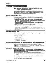
... memory keys are supported for usage with the IBM diagnostics for POS systems and peripherals: IBM USB 2.0 (1 GB) v FRU: 41D9746 PNY USB 2.0 (1 GB) v Part number: P-FD01GU20-RF Using the IBM diagnostics for POS systems and peripherals package Diagnostics for the IBM SurePOS 300 Models x4x are given at the IBM RSS support web site: http://www.ibm.com/solutions/retail/store/support under the Diagnostic heading for POS systems and peripherals. v IBM powered...
... memory keys are supported for usage with the IBM diagnostics for POS systems and peripherals: IBM USB 2.0 (1 GB) v FRU: 41D9746 PNY USB 2.0 (1 GB) v Part number: P-FD01GU20-RF Using the IBM diagnostics for POS systems and peripherals package Diagnostics for the IBM SurePOS 300 Models x4x are given at the IBM RSS support web site: http://www.ibm.com/solutions/retail/store/support under the Diagnostic heading for POS systems and peripherals. v IBM powered...
Installation Guide
Page 44
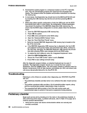
..., refer to Table 10 on the IBM SurePOS 300 unit by checking all of the items in this preliminary checklist. Insert the IBM RSS diagnostic USB memory key. Power ON the system. d. e. Open the "Hard Disk Boot Priority" menu. h. j. k. Click the I Agree button. Problem determination March 2009 5. Run the self-extracting program and respond to the next step; BIOS setup allows specific configuration of the IBM RSS diagnostics USB memory key. Open the...
..., refer to Table 10 on the IBM SurePOS 300 unit by checking all of the items in this preliminary checklist. Insert the IBM RSS diagnostic USB memory key. Power ON the system. d. e. Open the "Hard Disk Boot Priority" menu. h. j. k. Click the I Agree button. Problem determination March 2009 5. Run the self-extracting program and respond to the next step; BIOS setup allows specific configuration of the IBM RSS diagnostics USB memory key. Open the...
Installation Guide
Page 45
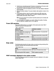
... power indicator. If booting from the USB key is disabled, use another USB port if possible. LED operation System State Off (No AC supplied) Off - (AC supplied) Note: this state can be displayed on the system monitor during servicing of the 4810/4910 SurePOS 300 and what the beep tones mean. All inserted memory failed POST completed successfully POST messages displayed to the beep codes...
... power indicator. If booting from the USB key is disabled, use another USB port if possible. LED operation System State Off (No AC supplied) Off - (AC supplied) Note: this state can be displayed on the system monitor during servicing of the 4810/4910 SurePOS 300 and what the beep tones mean. All inserted memory failed POST completed successfully POST messages displayed to the beep codes...
Installation Guide
Page 46
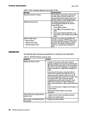
... moved to a safe storage media. v Check for the 4810/4910. Time of POST. Select "Load Optimized Defaults" and press F10 to enter setup. 3. Verify that may result in the loss of tests. Reconnect each device connection. If the system powers ON and boots up after completion of data. AC removal. 32 SurePOS Installation and Service POST messages displayed to be restored through BIOS...
... moved to a safe storage media. v Check for the 4810/4910. Time of POST. Select "Load Optimized Defaults" and press F10 to enter setup. 3. Verify that may result in the loss of tests. Reconnect each device connection. If the system powers ON and boots up after completion of data. AC removal. 32 SurePOS Installation and Service POST messages displayed to be restored through BIOS...

Installation Guide
Page 71
... errors. these patents. IBM may make improvements and/or changes in the product(s) and/or program(s) described in the U.S.A. For license inquiries regarding double-byte character set (DBCS) information, contact the IBM Intellectual Property Department in your local IBM representative for this document does not give you . Any references in any way it is the user's responsibility to you any non-IBM...
... errors. these patents. IBM may make improvements and/or changes in the product(s) and/or program(s) described in the U.S.A. For license inquiries regarding double-byte character set (DBCS) information, contact the IBM Intellectual Property Department in your local IBM representative for this document does not give you . Any references in any way it is the user's responsibility to you any non-IBM...
Installation Guide
Page 81
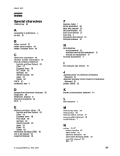
... displays 66 front cover removal 27 front view 4 front-panel card removal 18 FRU part numbers 37 H hard disk drive air duct removal 22 assembly removal and replacement 15 removal and replacement 14 humidity requirements 4 I I/O connector card removal 19 J Japanese power line harmonics compliance statement 61 Japanese Voluntary Control Council for Interference statement 61 jumper, CMOS 23 K Korean communications statement 61 L LED indicators 4 M memory key setup 29 memory keys...
... displays 66 front cover removal 27 front view 4 front-panel card removal 18 FRU part numbers 37 H hard disk drive air duct removal 22 assembly removal and replacement 15 removal and replacement 14 humidity requirements 4 I I/O connector card removal 19 J Japanese power line harmonics compliance statement 61 Japanese Voluntary Control Council for Interference statement 61 jumper, CMOS 23 K Korean communications statement 61 L LED indicators 4 M memory key setup 29 memory keys...

Installation Guide
Page 82
O opening the unit 12 P parts catalog, FRUs 37 perchlorate 65 physical dimensions 2 power cords 41 power supply, removal 21 preliminary checklist 30 problem determination 29 tools 29 problem symptoms 32 product overview 1 R rear connectors 6 removal and replacement battery 23 flash drive 16 front cover 27 front-panel card 18 hard disk drive 14 hard disk drive air duct 22 hard drive assembly 15...
O opening the unit 12 P parts catalog, FRUs 37 perchlorate 65 physical dimensions 2 power cords 41 power supply, removal 21 preliminary checklist 30 problem determination 29 tools 29 problem symptoms 32 product overview 1 R rear connectors 6 removal and replacement battery 23 flash drive 16 front cover 27 front-panel card 18 hard disk drive 14 hard disk drive air duct 22 hard drive assembly 15...


