

User Manual
Page 11
... The IBM® NetBAY™ Local Console Manager (LCM) provides flexible, centralized control of Servers CCO Cable Chained C2T Servers LCM Figure 1.1: Example LCM Configuration Analog Connection KCO Cables KCO Cables Switch Rack of Servers Rack of data center servers. The built-in memory of up to -end cable length of the CO simplifies configuration by assigning and retaining unique server identification codes for connecting servers, that operates over standard LAN connections. The CO cable is powered...
... The IBM® NetBAY™ Local Console Manager (LCM) provides flexible, centralized control of Servers CCO Cable Chained C2T Servers LCM Figure 1.1: Example LCM Configuration Analog Connection KCO Cables KCO Cables Switch Rack of Servers Rack of data center servers. The built-in memory of up to -end cable length of the CO simplifies configuration by assigning and retaining unique server identification codes for connecting servers, that operates over standard LAN connections. The CO cable is powered...

User Manual
Page 12
.... Consider equipment nameplate ratings for example, use a 2-wire extension cord in a closed rack assembly, the operation temperature of the equipment in the rack should be on overcurrent protection and supply wiring. 4 LCM Installer and User Guide Safety Precautions To avoid potential video and/or keyboard problems when using a backup uninterruptible power supply, power the computer, the monitor and the LCM off the supply. IBM warranties do not apply...
.... Consider equipment nameplate ratings for example, use a 2-wire extension cord in a closed rack assembly, the operation temperature of the equipment in the rack should be on overcurrent protection and supply wiring. 4 LCM Installer and User Guide Safety Precautions To avoid potential video and/or keyboard problems when using a backup uninterruptible power supply, power the computer, the monitor and the LCM off the supply. IBM warranties do not apply...

User Manual
Page 17
... well as other components in the rack, stabilize the rack in length • Rack mounting kit • LCM Installer and User Guide on CD • LCM Quick Installation Guide • One straight-through serial cable Additional items needed • One KCO cable per attached PS/2 server or switch • One UCO cable per attached USB server or switch • One CCO cable per attached IBM C2T server Installing Your LCM Your LCM ships...
... well as other components in the rack, stabilize the rack in length • Rack mounting kit • LCM Installer and User Guide on CD • LCM Quick Installation Guide • One straight-through serial cable Additional items needed • One KCO cable per attached PS/2 server or switch • One UCO cable per attached USB server or switch • One CCO cable per attached IBM C2T server Installing Your LCM Your LCM ships...

User Manual
Page 18
..., unless instructed otherwise in the installation and configuration procedures. • Connect and disconnect cables as described in the switch. 2. Cap the screw with the screw holes in the following table when installing, moving, or opening covers on your equipment rack. First, attach all cables from connectors. 4. With a Phillips screwdriver, fasten the mounting brackets to connect or disconnect signal cables. • Never turn on any...
..., unless instructed otherwise in the installation and configuration procedures. • Connect and disconnect cables as described in the switch. 2. Cap the screw with the screw holes in the following table when installing, moving, or opening covers on your equipment rack. First, attach all cables from connectors. 4. With a Phillips screwdriver, fasten the mounting brackets to connect or disconnect signal cables. • Never turn on any...

User Manual
Page 20
Follow the detailed set of procedures following Figure 2.3 to 16 chained servers per ARI port Server Server Server CAT 5 CAT 5 CAT 5 KVM Figure 2.3: Basic LCM Configuration Analog Port LCM Chained C2T Servers CAT 5 CCO CAT 5 ARI Ports IBM NetBAY Switch KCO Server Server Server Up to successfully install your LCM. 12 LCM Installer and User Guide Figure 2.2: LCM Horizontal Installation Cabling the LCM Figure 2.3 shows one possible configuration for your LCM.
Follow the detailed set of procedures following Figure 2.3 to 16 chained servers per ARI port Server Server Server CAT 5 CAT 5 CAT 5 KVM Figure 2.3: Basic LCM Configuration Analog Port LCM Chained C2T Servers CAT 5 CCO CAT 5 ARI Ports IBM NetBAY Switch KCO Server Server Server Up to successfully install your LCM. 12 LCM Installer and User Guide Figure 2.2: LCM Horizontal Installation Cabling the LCM Figure 2.3 shows one possible configuration for your LCM.

User Manual
Page 22
.... Settings - Set the pointer speed to mouse acceleration must be connecting to the second RJ45 connector on the LCM. 4. Control Panel - To connect a CCO cable to an ARI port on the KCO cable for your LCM. 2. Locate the CCO cables and CAT 5 cabling for Server 1. 6. Use the default Microsoft® Windows® PS/2 mouse driver for all servers you will be accessing the Windows NT system through the LCM. Control...
.... Settings - Set the pointer speed to mouse acceleration must be connecting to the second RJ45 connector on the LCM. 4. Control Panel - To connect a CCO cable to an ARI port on the KCO cable for your LCM. 2. Locate the CCO cables and CAT 5 cabling for Server 1. 6. Use the default Microsoft® Windows® PS/2 mouse driver for all servers you will be accessing the Windows NT system through the LCM. Control...

User Manual
Page 23
...) KCO Cable ARI Port KCO Cable Server 1 KCO Cable Server 2 Terminator Figure 2.4: Chaining Servers Together with KCO Cables Server 3 To chain servers together using UCO cables: 1. Attach one end of the chain, attach a terminator to the second RJ45 connector on the UCO cable for all servers you will be connecting to the USB and monitor ports on the UCO cable. 3. When you reach the end of the CAT 5 cabling that will connect the...
...) KCO Cable ARI Port KCO Cable Server 1 KCO Cable Server 2 Terminator Figure 2.4: Chaining Servers Together with KCO Cables Server 3 To chain servers together using UCO cables: 1. Attach one end of the chain, attach a terminator to the second RJ45 connector on the UCO cable for all servers you will be connecting to the USB and monitor ports on the UCO cable. 3. When you reach the end of the CAT 5 cabling that will connect the...
User Manual
Page 25
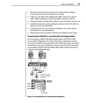
... cascaded switch. Chapter 2: Installation 17 1. Repeat steps 2-5 for your RCM or LCM. Connect the other . In a cascaded configuration, the remote and analog workstations can cascade a NetBAY 2x8 console switch under your switch. 2. Locate a length of the switch IBM NetBAY 2x8 Switch KVM Figure 2.7: Cascaded Multi-user Legacy Switch Configuration Connect the servers to your LCM. 4. Attach the keyboard, monitor and mouse connectors of your switch according to access different servers on...
... cascaded switch. Chapter 2: Installation 17 1. Repeat steps 2-5 for your RCM or LCM. Connect the other . In a cascaded configuration, the remote and analog workstations can cascade a NetBAY 2x8 console switch under your switch. 2. Locate a length of the switch IBM NetBAY 2x8 Switch KVM Figure 2.7: Cascaded Multi-user Legacy Switch Configuration Connect the servers to your LCM. 4. Attach the keyboard, monitor and mouse connectors of your switch according to access different servers on...

User Manual
Page 26
... will be preempted, you are powered by the servers, turn on the servers first and then turn on the remote workstation (English keyboard). For other operating systems, see the user guide that comes with the target server: 1. This means that server is accessing server 1 via KCO cable A and the remote user switches to the switch. 18 LCM Installer and User Guide Preemptive behavior By default, the console switch operates in a system: You may...
... will be preempted, you are powered by the servers, turn on the servers first and then turn on the remote workstation (English keyboard). For other operating systems, see the user guide that comes with the target server: 1. This means that server is accessing server 1 via KCO cable A and the remote user switches to the switch. 18 LCM Installer and User Guide Preemptive behavior By default, the console switch operates in a system: You may...

User Manual
Page 29
... IBM which has intuitive menus to configure your servers by name, port or by default when you connect a legacy switch to the LCM, the port numbering displays the ARI port first, then the port to which a server is connected. You will see Setting console security in the LCM system. Type in Figure 3.1, servers 06-03 and 01-02 are connected to view, configure and control servers in this Installer and User Guide. Viewing and Selecting Ports and Servers Use...
... IBM which has intuitive menus to configure your servers by name, port or by default when you connect a legacy switch to the LCM, the port numbering displays the ARI port first, then the port to which a server is connected. You will see Setting console security in the LCM system. Type in Figure 3.1, servers 06-03 and 01-02 are connected to view, configure and control servers in this Installer and User Guide. Viewing and Selecting Ports and Servers Use...

User Manual
Page 30
... time set and you press the key sequences before that server. CO cable is offline or is the ability to switch servers using a hotkey sequence. When you between the previous and current connections. Connected switch is depressed), type the first few characters of its name or number. To select servers: Double-click the server name, eID or port number. -orIf the display order of your server list...
... time set and you press the key sequences before that server. CO cable is offline or is the ability to switch servers using a hotkey sequence. When you between the previous and current connections. Connected switch is depressed), type the first few characters of its name or number. To select servers: Double-click the server name, eID or port number. -orIf the display order of your server list...

User Manual
Page 31
...Ø on the keyboard and not the keypad.) Status flag displays Free. (This only applies to quit the edit mode. The Main dialog box appears. 2. For delay time, type the number of seconds of the server or the eID number to establish it closes the pop-up box and returns... The following table describes how to use the keyboard and mouse to the currently selected device. Closes the current dialog box without saving changes and returns to move the cursor. Selects the OK button, then returns to the previous server, press Print Screen then Backspace. To select a server, press Print...
...Ø on the keyboard and not the keypad.) Status flag displays Free. (This only applies to quit the edit mode. The Main dialog box appears. 2. For delay time, type the number of seconds of the server or the eID number to establish it closes the pop-up box and returns... The following table describes how to use the keyboard and mouse to the currently selected device. Closes the current dialog box without saving changes and returns to move the cursor. Selects the OK button, then returns to the previous server, press Print Screen then Backspace. To select a server, press Print...

User Manual
Page 32
.... When editing a text box, these keys move the cursor within OSCAR. Select the Names button when initially setting up and down through Name and Port lists. Figure 3.2: Setup Dialog Box Use the Shift key to identify servers by unique names. Click Setup. To access the Setup menu: 1. Numbers Type from the Setup menu within the column. 24 LCM Installer and User Guide OSCAR Navigation Basics (continued) This Keystroke...
.... When editing a text box, these keys move the cursor within OSCAR. Select the Names button when initially setting up and down through Name and Port lists. Figure 3.2: Setup Dialog Box Use the Shift key to identify servers by unique names. Click Setup. To access the Setup menu: 1. Numbers Type from the Setup menu within the column. 24 LCM Installer and User Guide OSCAR Navigation Basics (continued) This Keystroke...

User Manual
Page 33
... to 16 servers. Flag Change display, timing, color or location of ports on an attached cascade switch. Scan Set up a custom scan pattern for Your Servers Feature Purpose Menu Change the server listing between numerically by port or eID number and alphabetically by the LCM. Enable the screen saver. NOTE: If a server is turned off, its respective CO cable will be accepted until the list update is automatically...
... to 16 servers. Flag Change display, timing, color or location of ports on an attached cascade switch. Scan Set up a custom scan pattern for Your Servers Feature Purpose Menu Change the server listing between numerically by port or eID number and alphabetically by the LCM. Enable the screen saver. NOTE: If a server is turned off, its respective CO cable will be accepted until the list update is automatically...

User Manual
Page 35
Choose the number of ports supported by your switch and click OK. 4. The Device Modify dialog box appears. Figure 3.6: Device Modify Dialog Box 3. To assign a device type: 1. Click Modify. For example, if the switch is connected to port 2, the switch port would be listed as 02 and each port to which you will notice the port numbering change to accommodate each server under it would be numbered sequentially 02...
Choose the number of ports supported by your switch and click OK. 4. The Device Modify dialog box appears. Figure 3.6: Device Modify Dialog Box 3. To assign a device type: 1. Click Modify. For example, if the switch is connected to port 2, the switch port would be listed as 02 and each port to which you will notice the port numbering change to accommodate each server under it would be numbered sequentially 02...

User Manual
Page 36
... servers and set a Screen Delay Time for OSCAR. 28 LCM Installer and User Guide NOTE: Changes made in the Device Modify dialog box are not saved until you click OK in the Main dialog box. Menu in the Devices dialog box. Select Name to display servers alphabetically by name. -orSelect eID to display servers numerically by port number. 2. Click Setup - To set a Screen Delay Time...
... servers and set a Screen Delay Time for OSCAR. 28 LCM Installer and User Guide NOTE: Changes made in the Device Modify dialog box are not saved until you click OK in the Main dialog box. Menu in the Devices dialog box. Select Name to display servers alphabetically by name. -orSelect eID to display servers numerically by port number. 2. Click Setup - To set a Screen Delay Time...

User Manual
Page 38
... Setup - Click OK to save settings. -orClick X to the Flag dialog box. You can establish a screen saver mode that engages after your analog port console. NOTE: If a password has been previously set or change your console will remain locked until you to set security on the title bar and drag to the desired location. The Security dialog box appears. c. Setting console security OSCAR enables...
... Setup - Click OK to save settings. -orClick X to the Flag dialog box. You can establish a screen saver mode that engages after your analog port console. NOTE: If a password has been previously set or change your console will remain locked until you to set security on the title bar and drag to the desired location. The Security dialog box appears. c. Setting console security OSCAR enables...

User Manual
Page 40
... communication re-established between the server and the LCM, functionality is selected. Reset PS/2. 32 LCM Installer and User Guide -orIf your mouse. In the Security dialog box, clear Enable Screen Saver. 2. A message box displays indicating that you want to delay activation of the screen saver mode disconnects the user from the use of Energy mode with monitors not compliant with ENERGY...
... communication re-established between the server and the LCM, functionality is selected. Reset PS/2. 32 LCM Installer and User Guide -orIf your mouse. In the Security dialog box, clear Enable Screen Saver. 2. A message box displays indicating that you want to delay activation of the screen saver mode disconnects the user from the use of Energy mode with monitors not compliant with ENERGY...

User Manual
Page 49
... COM port you have saved the firmware upgrade and unzip the file. 3. Click Load. ATTENTION : While downloading, do not use your computer, and switching to another window may cause the download to the drive where you have chosen, then turn on the server • Standard serial cable (DB-male) that no other program is used, not a null modem serial cable. • Verify in Advanced Port Settings...
... COM port you have saved the firmware upgrade and unzip the file. 3. Click Load. ATTENTION : While downloading, do not use your computer, and switching to another window may cause the download to the drive where you have chosen, then turn on the server • Standard serial cable (DB-male) that no other program is used, not a null modem serial cable. • Verify in Advanced Port Settings...

User Manual
Page 53
...figuration Port Number 1 Type Serial RS232 Connector DB9 Female Analog Port Number 1 Type PS/2 and VGA Connectors PS/2 MiniDIN and 15-pin D Dimensions Dimensions (HxWxD) 4.38 x 43.18 x 13.97 cm 1U form factor (1.72 x 17.00 x 5.75 in) Weight 1.6 kg (3.6 lb) without cables Heat Dissipation 17 BTU/Hr Power Consumption 5 W AC-input power 10 W maximum AC-input voltage rating 100...
...figuration Port Number 1 Type Serial RS232 Connector DB9 Female Analog Port Number 1 Type PS/2 and VGA Connectors PS/2 MiniDIN and 15-pin D Dimensions Dimensions (HxWxD) 4.38 x 43.18 x 13.97 cm 1U form factor (1.72 x 17.00 x 5.75 in) Weight 1.6 kg (3.6 lb) without cables Heat Dissipation 17 BTU/Hr Power Consumption 5 W AC-input power 10 W maximum AC-input voltage rating 100...


