
Owners Manual
Page 2
...operate the riding mower safely enough to prevent accidental starting , stopping, or turning on the ground. • Do not mow near rotating parts or under the influence of alcohol or drugs. • Watch for wheel weights or counterweights. • Keep machine free of California to...reproductive harm. Operate only at all slopes requires extra caution. Wash hands after handling. GENERAL OPERATION • Read, understand, and follow all parts to come to plow leaves or other debris build-up and down a hill in . 2 SLOPE OPERATION Slopes are recommended by putting your tractor...
...operate the riding mower safely enough to prevent accidental starting , stopping, or turning on the ground. • Do not mow near rotating parts or under the influence of alcohol or drugs. • Watch for wheel weights or counterweights. • Keep machine free of California to...reproductive harm. Operate only at all slopes requires extra caution. Wash hands after handling. GENERAL OPERATION • Read, understand, and follow all parts to come to plow leaves or other debris build-up and down a hill in . 2 SLOPE OPERATION Slopes are recommended by putting your tractor...

Owners Manual
Page 3
...; If machine stops while going uphill, disengage blades, shift into reverse and back down and behind before operating. TOWING • Tow only with manufacturer's recommended parts, when necessary. • Mower blades are sharp. Repair, if necessary, before storing. • If you last saw them . • Check brake operation frequently. Children who...
...; If machine stops while going uphill, disengage blades, shift into reverse and back down and behind before operating. TOWING • Tow only with manufacturer's recommended parts, when necessary. • Mower blades are sharp. Repair, if necessary, before storing. • If you last saw them . • Check brake operation frequently. Children who...
Owners Manual
Page 4
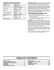
... OF CONTENTS SAFETY RULES 2-3 MAINTENANCE 14-18 PRODUCT SPECIFICATIONS 4 SERVICE AND ADJUSTMENTS 19-24 CUSTOMER RESPONSIBILITIES 4 STORAGE 25 ASSEMBLY 5-6 TROUBLESHOOTING 26-27 OPERATION 7-13 REPAIR PARTS 28-42 MAINTENANCE SCHEDULE 14 4 A spark arrester for and using your purchase of this manual. CCA: Case Size: 28 230 U1R Blade Bolt Torque: 45...
... OF CONTENTS SAFETY RULES 2-3 MAINTENANCE 14-18 PRODUCT SPECIFICATIONS 4 SERVICE AND ADJUSTMENTS 19-24 CUSTOMER RESPONSIBILITIES 4 STORAGE 25 ASSEMBLY 5-6 TROUBLESHOOTING 26-27 OPERATION 7-13 REPAIR PARTS 28-42 MAINTENANCE SCHEDULE 14 4 A spark arrester for and using your purchase of this manual. CCA: Case Size: 28 230 U1R Blade Bolt Torque: 45...
Owners Manual
Page 5
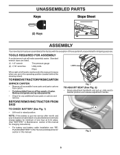
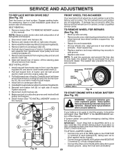
...; Lift hood to desired position and release adjustment handle. LABEL TO REMOVE TRACTOR FROM CARTON UNPACK CARTON • Remove all accessible loose parts and parts cartons from carton . • Cut along dotted lines on label (label is located between terminals) charge battery for minimum of one ...listed. (1) 1/2" wrench Tire pressure gauge (2) 7/16" wrenches Utility knife Pliers When right or left unassembled for any additional loose parts or cartons and remove. Standard wrench sizes are in this battery is put into service after month and year indicated on all four ...
...; Lift hood to desired position and release adjustment handle. LABEL TO REMOVE TRACTOR FROM CARTON UNPACK CARTON • Remove all accessible loose parts and parts cartons from carton . • Cut along dotted lines on label (label is located between terminals) charge battery for minimum of one ...listed. (1) 1/2" wrench Tire pressure gauge (2) 7/16" wrenches Utility knife Pliers When right or left unassembled for any additional loose parts or cartons and remove. Standard wrench sizes are in this battery is put into service after month and year indicated on all four ...
Owners Manual
Page 6
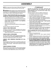
... this manual). • Roll tractor forward off the skid. PLEASE REVIEW THE FOLLOWING CHECKLIST: ✓ All assembly instructions have been completed. ✓ No remaining loose parts in carton. ✓ Battery is properly prepared and charged. ✓ Seat is adjusted comfortably and tightened securely. ✓ All tires are working properly (See the...
... this manual). • Roll tractor forward off the skid. PLEASE REVIEW THE FOLLOWING CHECKLIST: ✓ All assembly instructions have been completed. ✓ No remaining loose parts in carton. ✓ Battery is properly prepared and charged. ✓ Seat is adjusted comfortably and tightened securely. ✓ All tires are working properly (See the...
Owners Manual
Page 15
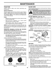
... PRESENCE SYSTEM AND REVERSE OPERATION SYSTEM (ROS) (See Fig. 13) Be sure operator presence and reverse operation systems are working properly. NOTE: Protect your local parts dealer. IMPORTANT: SPECIAL BLADE BOLT HEAT TREATED. CHECK REVERSE OPERATION (ROS) SYSTEM • When the engine is not necessary. TO CLEAN BATTERY AND TERMINALS Corrosion...
... PRESENCE SYSTEM AND REVERSE OPERATION SYSTEM (ROS) (See Fig. 13) Be sure operator presence and reverse operation systems are working properly. NOTE: Protect your local parts dealer. IMPORTANT: SPECIAL BLADE BOLT HEAT TREATED. CHECK REVERSE OPERATION (ROS) SYSTEM • When the engine is not necessary. TO CLEAN BATTERY AND TERMINALS Corrosion...
Owners Manual
Page 17
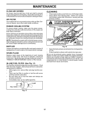
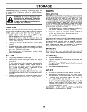
... cooling shrouds are kept clean at the beginning of all foreign matter. • Clean debris from steering plate. CAUTION: Avoid all pinch points and movable parts (See Fig. 18) CLUTCH/BRAKE PEDAL CLEAN TOP SIDE STEERING PLATE STEERING SYSTEM, DASH, FENDER AND MOWER NOT SHOWN CAUTION: PINCH POINTS Fig. 18 •...
... cooling shrouds are kept clean at the beginning of all foreign matter. • Clean debris from steering plate. CAUTION: Avoid all pinch points and movable parts (See Fig. 18) CLUTCH/BRAKE PEDAL CLEAN TOP SIDE STEERING PLATE STEERING SYSTEM, DASH, FENDER AND MOWER NOT SHOWN CAUTION: PINCH POINTS Fig. 18 •...
Owners Manual
Page 18
... could expose you or others to thrown objects from the nozzle washout port. 10.Move the tractor to lock the adapter on its surface as part of the mower deck. Pull back the lock collar of the nozzle adapter and push the adapter onto the deck washout port at the left...
... could expose you or others to thrown objects from the nozzle washout port. 10.Move the tractor to lock the adapter on its surface as part of the mower deck. Pull back the lock collar of the nozzle adapter and push the adapter onto the deck washout port at the left...
Owners Manual
Page 19
... brake. • Place attachment clutch in "DISENGAGED" position. • Turn ignition key to "STOP" and remove key. • Make sure the blades and all moving parts have completely stopped. • Disconnect spark plug wire from spark plug and place wire where it cannot come in contact with retainer spring. • Repeat...
... brake. • Place attachment clutch in "DISENGAGED" position. • Turn ignition key to "STOP" and remove key. • Make sure the blades and all moving parts have completely stopped. • Disconnect spark plug wire from spark plug and place wire where it cannot come in contact with retainer spring. • Repeat...
Owners Manual
Page 23
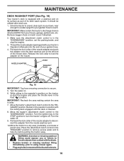
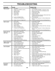
... to start the engine, it should be purchased from tractor. Always wear eye protection when around electric clutch (G). 8. H B A C D J E F 02953 electric Fig. 33 If your local parts dealer. If "jumper cables" are not adjustable. THE OTHER VEHICLE MUST ALSO BE A 12 VOLT SYSTEM. DO NOT USE YOUR TRACTOR BATTERY TO START OTHER...
... to start the engine, it should be purchased from tractor. Always wear eye protection when around electric clutch (G). 8. H B A C D J E F 02953 electric Fig. 33 If your local parts dealer. If "jumper cables" are not adjustable. THE OTHER VEHICLE MUST ALSO BE A 12 VOLT SYSTEM. DO NOT USE YOUR TRACTOR BATTERY TO START OTHER...
Owners Manual
Page 25
... store battery directly on stabilizer container. ENGINE FUEL SYSTEM IMPORTANT: IT IS IMPORTANT TO PREVENT GUM DEPOSITS FROM FORMING IN ESSENTIAL FUEL SYSTEM PARTS SUCH AS CARBURETOR, FUEL FILTER, FUEL HOSE, OR TANK DURING STORAGE. ALSO, EXPERIENCE INDICATES THAT ALCOHOL BLENDED FUELS (CALLED GASOHOL OR USING... oil. (See "ENGINE" in the tank inside a building where fumes may occur. • Use fresh fuel next season. Inspect moving parts for winter storage. Always follow the mix ratio found on concrete or damp surfaces. NOTE: Fuel stabilizer is removed from one ounce of this...
... store battery directly on stabilizer container. ENGINE FUEL SYSTEM IMPORTANT: IT IS IMPORTANT TO PREVENT GUM DEPOSITS FROM FORMING IN ESSENTIAL FUEL SYSTEM PARTS SUCH AS CARBURETOR, FUEL FILTER, FUEL HOSE, OR TANK DURING STORAGE. ALSO, EXPERIENCE INDICATES THAT ALCOHOL BLENDED FUELS (CALLED GASOHOL OR USING... oil. (See "ENGINE" in the tank inside a building where fumes may occur. • Use fresh fuel next season. Inspect moving parts for winter storage. Always follow the mix ratio found on concrete or damp surfaces. NOTE: Fuel stabilizer is removed from one ounce of this...
Owners Manual
Page 26
... Corroded battery terminals. 6. Check all wiring. 7. Cutting too much grass/too fast. 1. Spark plug wire loose. 10. Loose/damaged part(s). 1. Bad spark plug. 5. Check all wiring. 9. Hard to start CAUSE 1. See "To Adjust Carburetor" in Service Adjustments section. ...refill tank with fresh, clean gas. 9. Replace fuel filter. 5. Attachment clutch is engaged. 3. Build-up of fuel. 2. Tighten loose part(s). See "To Adjust Carburetor" in Service Adjustments section. 8. Loose or damaged wiring. 7. Check/replace solenoid or starter. 9. Depress brake ...
... Corroded battery terminals. 6. Check all wiring. 7. Cutting too much grass/too fast. 1. Spark plug wire loose. 10. Loose/damaged part(s). 1. Bad spark plug. 5. Check all wiring. 9. Hard to start CAUSE 1. See "To Adjust Carburetor" in Service Adjustments section. ...refill tank with fresh, clean gas. 9. Replace fuel filter. 5. Attachment clutch is engaged. 3. Build-up of fuel. 2. Tighten loose part(s). See "To Adjust Carburetor" in Service Adjustments section. 8. Loose or damaged wiring. 7. Check/replace solenoid or starter. 9. Depress brake ...
Owners Manual
Page 27
... not rotate 1. Check/clean all connections. 3. Replace mower drive belt. 9. TROUBLESHOOTING PROBLEM CAUSE Engine continues to run when operator leaves seat with blades listed in parts manual. 11. Faulty operator-safety presence control system. CORRECTION 1. uneven Mower blades will not charge 1. Worn, bent or loose blade. 2. Worn/damaged mower drive belt...
... not rotate 1. Check/clean all connections. 3. Replace mower drive belt. 9. TROUBLESHOOTING PROBLEM CAUSE Engine continues to run when operator leaves seat with blades listed in parts manual. 11. Faulty operator-safety presence control system. CORRECTION 1. uneven Mower blades will not charge 1. Worn, bent or loose blade. 2. Worn/damaged mower drive belt...
Owners Manual
Page 28
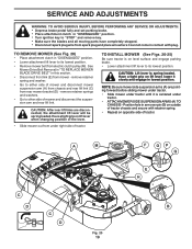
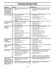
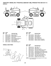
...24 9 532 14 50-05 DESCRIPTION Decal, Operators Badge, Hood Decal, Emblem Panel SD Decal, Eng. TRACTOR - YTH22V42LS (96043011300), PRODUCT NO. 960 43 01-13 DECALS 2 56 2 3 1 7 8 9 4 11 10 7 KEY PART NO. NO. 10 532 41 86-00 11 532 19 87-85 - - 532 16 69-60 - - ... Bypass Pad, Footrest, LH Pad, Footrest, RH Manual, Owner's (English) Manual, Owner's (Spanish) WHEELS AND TIRES 1 2 11 3 4 7 10 6 wheel_art_1-tex 5 9 8 KEY PART NO. NO. MODEL NO. Tube) NOTE: All component dimensions given in U.S. Decal, Replacement Decal, No Step Decal, Warning Decal, Battery Dnge/Poi KEY...
...24 9 532 14 50-05 DESCRIPTION Decal, Operators Badge, Hood Decal, Emblem Panel SD Decal, Eng. TRACTOR - YTH22V42LS (96043011300), PRODUCT NO. 960 43 01-13 DECALS 2 56 2 3 1 7 8 9 4 11 10 7 KEY PART NO. NO. 10 532 41 86-00 11 532 19 87-85 - - 532 16 69-60 - - ... Bypass Pad, Footrest, LH Pad, Footrest, RH Manual, Owner's (English) Manual, Owner's (Spanish) WHEELS AND TIRES 1 2 11 3 4 7 10 6 wheel_art_1-tex 5 9 8 KEY PART NO. NO. MODEL NO. Tube) NOTE: All component dimensions given in U.S. Decal, Replacement Decal, No Step Decal, Warning Decal, Battery Dnge/Poi KEY...
Owners Manual
Page 31
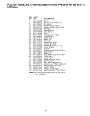
... Harness 12-Volt Pigtail 105 532 40 75-68 Switch Reverse TT Pedal Control NOTE: All component dimensions given in U.S. NO. YTH22V42LS (96043011300), PRODUCT NO. 960 43 01-13 ELECTRICAL KEY PART NO. DESCRIPTION 1 532 16 34-65 Battery 2 874 76 04-12 Bolt Hex Head 1/4-20 x 3/4 8 532 18 64-91 Box...
... Harness 12-Volt Pigtail 105 532 40 75-68 Switch Reverse TT Pedal Control NOTE: All component dimensions given in U.S. NO. YTH22V42LS (96043011300), PRODUCT NO. 960 43 01-13 ELECTRICAL KEY PART NO. DESCRIPTION 1 532 16 34-65 Battery 2 874 76 04-12 Bolt Hex Head 1/4-20 x 3/4 8 532 18 64-91 Box...

Owners Manual
Page 33
Dash Hood Lens LH Grille/Lens Asm. YTH22V42LS (96043011300), PRODUCT NO. 960 43 01-13 CHASSIS KEY PART NO. NO. 2 532 41 22-82 3 532 43 97-52 5 532 43 74-69 14 532 44 11-77 15 532 43 97-33 18 ... given in U.S. TRACTOR - Chassis Dash Lower Bolt 5/16-18 x 1-1/4 Screw 5/16-18 x 3/4 Insert Reflective RH Nut Lock Hex Flange 5/16-18 Plate Deck Lift KEY PART NO. inches 1 inch = 25.4 mm 33 Lens RH Screw 5/16-18 x 3/4 Fender Drawbar Upper Screw Thdrol 5/16-18 x 1/2 Screw 10 x 0.750 BOS Thread Bumper Dash...
Dash Hood Lens LH Grille/Lens Asm. YTH22V42LS (96043011300), PRODUCT NO. 960 43 01-13 CHASSIS KEY PART NO. NO. 2 532 41 22-82 3 532 43 97-52 5 532 43 74-69 14 532 44 11-77 15 532 43 97-33 18 ... given in U.S. TRACTOR - Chassis Dash Lower Bolt 5/16-18 x 1-1/4 Screw 5/16-18 x 3/4 Insert Reflective RH Nut Lock Hex Flange 5/16-18 Plate Deck Lift KEY PART NO. inches 1 inch = 25.4 mm 33 Lens RH Screw 5/16-18 x 3/4 Fender Drawbar Upper Screw Thdrol 5/16-18 x 1/2 Screw 10 x 0.750 BOS Thread Bumper Dash...
Owners Manual
Page 35
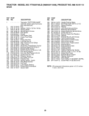
YTH22V42LS (96043011300), PRODUCT NO. 960 43 01-13 DRIVE KEY PART NO. NO. inches 1 inch = 25.4 mm 35 DESCRIPTION 1 Transaxle, TUFFTORQ K46BT (426120) (Order parts from transaxle manufacturer) 2 532 12 35-83 Key 15 819 13 13-16 Washer 13/32 x 13/16 x 16 Ga. 17 532 41 36-78 ... Push 167 532 40 52-57 Latch Brake Parking 170 532 41 34-30 Keeper Belt Centerspan 183 532 13 70-57 Spacer Split KEY PART NO. MODEL NO. DESCRIPTION 184 532 44 14-55 Handle Parking Brake 185 872 11 06-22 Bolt Rdhd Sqnk 3/8-16 x 2-1/2 186 532 19 43...
YTH22V42LS (96043011300), PRODUCT NO. 960 43 01-13 DRIVE KEY PART NO. NO. inches 1 inch = 25.4 mm 35 DESCRIPTION 1 Transaxle, TUFFTORQ K46BT (426120) (Order parts from transaxle manufacturer) 2 532 12 35-83 Key 15 819 13 13-16 Washer 13/32 x 13/16 x 16 Ga. 17 532 41 36-78 ... Push 167 532 40 52-57 Latch Brake Parking 170 532 41 34-30 Keeper Belt Centerspan 183 532 13 70-57 Spacer Split KEY PART NO. MODEL NO. DESCRIPTION 184 532 44 14-55 Handle Parking Brake 185 872 11 06-22 Bolt Rdhd Sqnk 3/8-16 x 2-1/2 186 532 19 43...
Owners Manual
Page 37
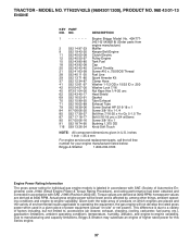
...77 90 817 00 06-16 91 532 18 74-95 116 539 13 26-24 Engine Briggs Model No. 40H7772421-G1(438218) (Order parts from engine manufacture) Muffler Keeper Belt Engine Clutch Electric Pulley Engine Tank Fuel Cap Control Throttle Screw #10 x .750 BOS Thread Fuel ...of Automotive Engineers) code J1940 (Small Engine Power & Torque Rating Procedure), and rating performance has been obtained and corrected in U.S. YTH22V42LS (96043011300), PRODUCT NO. 960 43 01-13 ENGINE KEY PART NO. NO. This difference is labeled in accordance with SAE J1995 (Revision 2002-05). MODEL NO. inches 1 inch = 25...
...77 90 817 00 06-16 91 532 18 74-95 116 539 13 26-24 Engine Briggs Model No. 40H7772421-G1(438218) (Order parts from engine manufacture) Muffler Keeper Belt Engine Clutch Electric Pulley Engine Tank Fuel Cap Control Throttle Screw #10 x .750 BOS Thread Fuel ...of Automotive Engineers) code J1940 (Small Engine Power & Torque Rating Procedure), and rating performance has been obtained and corrected in U.S. YTH22V42LS (96043011300), PRODUCT NO. 960 43 01-13 ENGINE KEY PART NO. NO. This difference is labeled in accordance with SAE J1995 (Revision 2002-05). MODEL NO. inches 1 inch = 25...
Owners Manual
Page 38
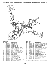
... 70-79 Washer Thrust NOTE: All component dimensions given in U.S. Nut Lock Flg. 3/8-16 unc KEY PART NO. inches 1 inch = 25.4 mm 38 DESCRIPTION 51 873 94 08-00 Nut Hex Jam Toplock... Support Lower Insert, Wheel Steering Screw 3/8-16 x 3/4 Gear, Sector Plate Washer 9/16 ID x 2-3/8 OD 12 Ga. YTH22V42LS (96043011300), PRODUCT NO. 960 43 01-13 STEERING ASSEMBLY 26 51 45 1 21 16 13 64 28 28 63 22 60... 67 7 55 78 2 8 6 9 7 55 67 6 14 5 62 14 15 54 66 54 13 13 8 53 Steering-tex_LEGND2_37 KEY PART NO. NO. 1 532 43 97-40 2 532 19 59-68 4 532 40 30-89 5 532 40 30-90 6 532 12 49-31...
... 70-79 Washer Thrust NOTE: All component dimensions given in U.S. Nut Lock Flg. 3/8-16 unc KEY PART NO. inches 1 inch = 25.4 mm 38 DESCRIPTION 51 873 94 08-00 Nut Hex Jam Toplock... Support Lower Insert, Wheel Steering Screw 3/8-16 x 3/4 Gear, Sector Plate Washer 9/16 ID x 2-3/8 OD 12 Ga. YTH22V42LS (96043011300), PRODUCT NO. 960 43 01-13 STEERING ASSEMBLY 26 51 45 1 21 16 13 64 28 28 63 22 60... 67 7 55 78 2 8 6 9 7 55 67 6 14 5 62 14 15 54 66 54 13 13 8 53 Steering-tex_LEGND2_37 KEY PART NO. NO. 1 532 43 97-40 2 532 19 59-68 4 532 40 30-89 5 532 40 30-90 6 532 12 49-31...

Owners Manual
Page 39
... Pivot Fender Strap, Asm Fender Nut, Lock w/Ins. 3/8-16 unc Spring, Seat Cprsn Bolt 5/16-18 unc x 3/4 w/Sems Pan, Seat Bolt, Shoulder 5/16-18 3 KEY PART NO. YTH22V42LS (96043011300), PRODUCT NO. 960 43 01-13 SEAT ASSEMBLY 1 8 7 41 40 88 7 8 10 21 6 37 6 37 2 44 43 21 seat-tex_6.5SL_3 KEY... PART NO. inches 1 inch = 25.4 mm 39 NO. 37 873 80 05-00 40 532 43 98-71 41 532 19 82-00 43 874 76 ...
... Pivot Fender Strap, Asm Fender Nut, Lock w/Ins. 3/8-16 unc Spring, Seat Cprsn Bolt 5/16-18 unc x 3/4 w/Sems Pan, Seat Bolt, Shoulder 5/16-18 3 KEY PART NO. YTH22V42LS (96043011300), PRODUCT NO. 960 43 01-13 SEAT ASSEMBLY 1 8 7 41 40 88 7 8 10 21 6 37 6 37 2 44 43 21 seat-tex_6.5SL_3 KEY... PART NO. inches 1 inch = 25.4 mm 39 NO. 37 873 80 05-00 40 532 43 98-71 41 532 19 82-00 43 874 76 ...


