
Owners Manual
Page 6
... charged. ✓ Seat is adjusted comfortably and tightened securely. ✓ All tires are shown for leveling). ✓ Check mower and drive belts. See that are properly inflated. (For shipping purposes, the tires were overinflated at the factory). ✓ Be sure mower deck is in ...Reverse Op- Be sure they are properly clamped. ✓ Before driving tractor, be properly leveled. CHECK FOR PROPER POSITION OF ALL BELTS See the figures that all connections are still secure and wires are routed properly around pulleys and inside all controls, their location and ...
... charged. ✓ Seat is adjusted comfortably and tightened securely. ✓ All tires are shown for leveling). ✓ Check mower and drive belts. See that are properly inflated. (For shipping purposes, the tires were overinflated at the factory). ✓ Be sure mower deck is in ...Reverse Op- Be sure they are properly clamped. ✓ Before driving tractor, be properly leveled. CHECK FOR PROPER POSITION OF ALL BELTS See the figures that all connections are still secure and wires are routed properly around pulleys and inside all controls, their location and ...
Owners Manual
Page 13
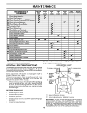
... Blades T Lubrication Chart 0 Check Battery Level R Clean Battery and Terminals Clean Debris Off Steering Plate Check Transaxle Cooling Check Mower Levelness Check V-Belts Check Engine Oil Level Change Engine Oil (with maintenance-free battery. 5 - A new spark plug and clean air filter assure proper air-fuel.... • At least once a year you should replace the spark plug, clean or replace air filter, and check blades and belts for wear. Some adjustments will need to be made periodically to operator abuse or negligence. GENERAL RECOMMENDATIONS LUBRICATION CHART The warranty on this...
... Blades T Lubrication Chart 0 Check Battery Level R Clean Battery and Terminals Clean Debris Off Steering Plate Check Transaxle Cooling Check Mower Levelness Check V-Belts Check Engine Oil Level Change Engine Oil (with maintenance-free battery. 5 - A new spark plug and clean air filter assure proper air-fuel.... • At least once a year you should replace the spark plug, clean or replace air filter, and check blades and belts for wear. Some adjustments will need to be made periodically to operator abuse or negligence. GENERAL RECOMMENDATIONS LUBRICATION CHART The warranty on this...
Owners Manual
Page 14
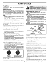
...or petroleum jelly. • Reinstall battery (See "REPLACING BATTERY" in the SERVICE AND ADJUSTMENTS section of your warranty. Fig. 14 V-BELTS BLADE CARE Check V-belts for deterioration and wear after 100 hours For best results mower blades must be checked and adjusted. (See "TO CHECK BRAKE" in ...the ROS "ON" position and the attachment clutch engaged, any attempt by the manufacturer of this manual). Replace belts if they begin to slip from your hands with gloves and/or wrap blade with heavy cloth. • Remove blade bolt by turning counterclockwise....
...or petroleum jelly. • Reinstall battery (See "REPLACING BATTERY" in the SERVICE AND ADJUSTMENTS section of your warranty. Fig. 14 V-BELTS BLADE CARE Check V-belts for deterioration and wear after 100 hours For best results mower blades must be checked and adjusted. (See "TO CHECK BRAKE" in ...the ROS "ON" position and the attachment clutch engaged, any attempt by the manufacturer of this manual). Replace belts if they begin to slip from your hands with gloves and/or wrap blade with heavy cloth. • Remove blade bolt by turning counterclockwise....
Owners Manual
Page 16
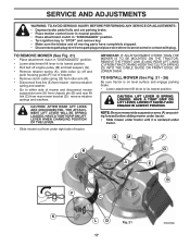
... in mower with the cutting deck engaged until the deck is directed AWAY from steering plate. Debris can restrict clutch/brake pedal shaft movement, causing belt slip and loss of the mower deck. Make sure the attachment clutch control is clear. 7. Move the tractor's attachment clutch control to help dry before...
... in mower with the cutting deck engaged until the deck is directed AWAY from steering plate. Debris can restrict clutch/brake pedal shaft movement, causing belt slip and loss of the mower deck. Make sure the attachment clutch control is clear. 7. Move the tractor's attachment clutch control to help dry before...
Owners Manual
Page 17
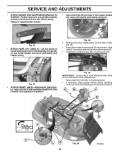
.... • Slide mower under tractor until it cannot come in "DISENGAGED" position. • Lower attachment lift lever to its lowest position. • Roll belt off engine pulley (M) and belt keepers (G). • Remove retainer spring (K), slide collar (L) off and push housing guide (P) out of mower and disconnect mower suspension arm (A) from chassis pin...
.... • Slide mower under tractor until it cannot come in "DISENGAGED" position. • Lower attachment lift lever to its lowest position. • Roll belt off engine pulley (M) and belt keepers (G). • Remove retainer spring (K), slide collar (L) off and push housing guide (P) out of mower and disconnect mower suspension arm (A) from chassis pin...
Owners Manual
Page 18
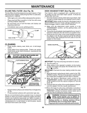
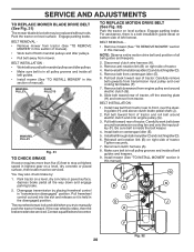
... (F). F J H Fig. 24 • Hook end of clutch cable spring (Q) into hole in idler arm (R). • Push clutch cable housing guide (P) into hole in belt keepers (G). G M F G A E B P C K LD Fig. 26 18 Lift rear corner of mower and position slot in link assembly over pin (B) on outside of... washer and retainer spring. Position hole in arm over pin (D) on rear mower bracket and secure with retainer spring (K). • Install belt on opposite side of tractor. • Insert end of tractor chassis and secure with retainer spring. • Repeat on engine pulley (M),...
... (F). F J H Fig. 24 • Hook end of clutch cable spring (Q) into hole in idler arm (R). • Push clutch cable housing guide (P) into hole in belt keepers (G). G M F G A E B P C K LD Fig. 26 18 Lift rear corner of mower and position slot in link assembly over pin (B) on outside of... washer and retainer spring. Position hole in arm over pin (D) on rear mower bracket and secure with retainer spring (K). • Install belt on opposite side of tractor. • Insert end of tractor chassis and secure with retainer spring. • Repeat on engine pulley (M),...
Owners Manual
Page 20
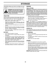
... rotate, then the brake needs to stop at highest speed in highest gear on bottom side of tractor. 4. For assistance, there is a belt installation guide decal on a level, dry concrete or paved surface, then brake must lock and skid when you try to front, over cooling... disengaged" position. Reinstall anti-rotation link (B) on right side of left footrest. Remove mower (See "TO REMOVE MOWER" section in this manual). Remove belt from engine pulley and around electric clutch and onto engine pulley (G). 3. Install mower (See "TO INSTALL MOWER" section in this section of manual). &#...
... rotate, then the brake needs to stop at highest speed in highest gear on bottom side of tractor. 4. For assistance, there is a belt installation guide decal on a level, dry concrete or paved surface, then brake must lock and skid when you try to front, over cooling... disengaged" position. Reinstall anti-rotation link (B) on right side of left footrest. Remove mower (See "TO REMOVE MOWER" section in this manual). Remove belt from engine pulley and around electric clutch and onto engine pulley (G). 3. Install mower (See "TO INSTALL MOWER" section in this section of manual). &#...
Owners Manual
Page 23
... enclosure. Store in a clean, dry area. • Clean entire tractor (See "CLEANING" in the Maintenance section of this manual). • Inspect and replace belts, if necessary (See belt replacement instructions in the Service and Adjustments section of this manual). WARNING: Never store the tractor with battery terminals. • If battery is to...
... enclosure. Store in a clean, dry area. • Clean entire tractor (See "CLEANING" in the Maintenance section of this manual). • Inspect and replace belts, if necessary (See belt replacement instructions in the Service and Adjustments section of this manual). WARNING: Never store the tractor with battery terminals. • If battery is to...
Owners Manual
Page 25
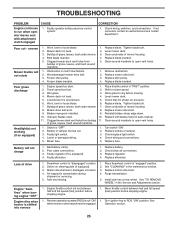
...deck not level. 3. Clogged mower deck vent holes from buildup 11. Frozen blade mandrel. 1. Replace blade mandrel. 5. Replace mower drive belt. 3. Place throttle control in "disengaged" position. 2. Allow grass to dry before stopping engine. 1. Check tires for proper air pressure. 6.... too slow. 1. Low/uneven tire air pressure. 5. Tighten blade bolt. 7. Clean underside of mower housing. 4. Replace mower drive belt. 9. Turn switch "ON". 2. Battery will not rotate 1. Level mower deck. 5. Buildup of grass, leaves, and trash around mandrels ...
...deck not level. 3. Clogged mower deck vent holes from buildup 11. Frozen blade mandrel. 1. Replace blade mandrel. 5. Replace mower drive belt. 3. Place throttle control in "disengaged" position. 2. Allow grass to dry before stopping engine. 1. Check tires for proper air pressure. 6.... too slow. 1. Low/uneven tire air pressure. 5. Tighten blade bolt. 7. Clean underside of mower housing. 4. Replace mower drive belt. 9. Turn switch "ON". 2. Battery will not rotate 1. Level mower deck. 5. Buildup of grass, leaves, and trash around mandrels ...
Owners Manual
Page 26
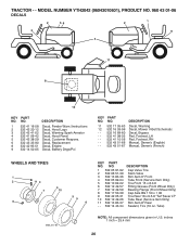
... - - 532 16 69-60 - - 532 41 08-05 - - 532 41 10-56 - - 532 43 51-66 - - 532 43 51-67 DESCRIPTION Decal, Warning Decal, Mower V-Belt Schematic Decal, Bypass Pad, Footrest, LH Pad, Footrest, RH Manual, Owner's (English) Manual, Owner's (French) WHEELS AND TIRES 1 2 11 3 4 7 10 6 wheel_art_1-tex 5 9 8 KEY PART...Decal, Warning Spark Arrestor Decal, Hood Panel Decal, Customer Respons. Decal, Replacement Decal, Engine Decal, Battery Dnge/Poi KEY PART NO. TRACTOR - - MODEL NUMBER YTH2042 (96043010601), PRODUCT NO. 960 43 01-06 DECALS 2 56 2 1 3 9 4 11 8 12 KEY PART NO.
... - - 532 16 69-60 - - 532 41 08-05 - - 532 41 10-56 - - 532 43 51-66 - - 532 43 51-67 DESCRIPTION Decal, Warning Decal, Mower V-Belt Schematic Decal, Bypass Pad, Footrest, LH Pad, Footrest, RH Manual, Owner's (English) Manual, Owner's (French) WHEELS AND TIRES 1 2 11 3 4 7 10 6 wheel_art_1-tex 5 9 8 KEY PART...Decal, Warning Spark Arrestor Decal, Hood Panel Decal, Customer Respons. Decal, Replacement Decal, Engine Decal, Battery Dnge/Poi KEY PART NO. TRACTOR - - MODEL NUMBER YTH2042 (96043010601), PRODUCT NO. 960 43 01-06 DECALS 2 56 2 1 3 9 4 11 8 12 KEY PART NO.
Owners Manual
Page 33
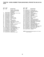
...06-00 Lock Nut 3/8-16 52 532 19 43-26 Idler V-Groove 910" Offset 56 532 13 09-69 V-Belt, Drive 64 532 19 62-00 Shaft Asm. NO. inches 1 inch = 25.4 mm 33 DESCRIPTION 166 532 ...-31 Bracket Pulley Idler 221 532 40 31-87 Retainer Spring Clip Handle 225 532 40 33-19 Keeper Belt Transaxle 226 532 40 15-64 Bracket Mount Torque 230 532 18 89-67 Washer Harden .793 x 1.... 532 40 52-96 Washer Serrated 279 532 41 31-50 Link Shift NOTE: All component dimensions given in U.S. MODEL NUMBER YTH2042 (96043010601), PRODUCT NO. 960 43 01-06 DRIVE KEY PART NO. NO. TRACTOR - - Pedal Brake Control 70 532 ...
...06-00 Lock Nut 3/8-16 52 532 19 43-26 Idler V-Groove 910" Offset 56 532 13 09-69 V-Belt, Drive 64 532 19 62-00 Shaft Asm. NO. inches 1 inch = 25.4 mm 33 DESCRIPTION 166 532 ...-31 Bracket Pulley Idler 221 532 40 31-87 Retainer Spring Clip Handle 225 532 40 33-19 Keeper Belt Transaxle 226 532 40 15-64 Bracket Mount Torque 230 532 18 89-67 Washer Harden .793 x 1.... 532 40 52-96 Washer Serrated 279 532 41 31-50 Link Shift NOTE: All component dimensions given in U.S. MODEL NUMBER YTH2042 (96043010601), PRODUCT NO. 960 43 01-06 DRIVE KEY PART NO. NO. TRACTOR - - Pedal Brake Control 70 532 ...
Owners Manual
Page 35
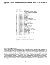
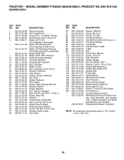
MODEL NUMBER YTH2042 (96043010601), PRODUCT NO. 960 43 01-06 ENGINE KEY PART NO. inches 1 inch = 25.4 mm For engine service and replacement parts, call the toll free ... variability. NO. TRACTOR - - DESCRIPTION 1 Engine Briggs Model No. 3317771372-G1 (Order parts from engine manufacturer) 2 532 18 86-55 Muffler 9 532 19 43-20 Keeper Belt Engine 12 532 40 54-71 Pulley Engine 15 532 41 41-51 Tank Fuel 18 532 43 02-13 Cap Asm 20 532 40...
MODEL NUMBER YTH2042 (96043010601), PRODUCT NO. 960 43 01-06 ENGINE KEY PART NO. inches 1 inch = 25.4 mm For engine service and replacement parts, call the toll free ... variability. NO. TRACTOR - - DESCRIPTION 1 Engine Briggs Model No. 3317771372-G1 (Order parts from engine manufacturer) 2 532 18 86-55 Muffler 9 532 19 43-20 Keeper Belt Engine 12 532 40 54-71 Pulley Engine 15 532 41 41-51 Tank Fuel 18 532 43 02-13 Cap Asm 20 532 40...
Owners Manual
Page 39
... Thdrol Rolling Wsh Hd Washer, Spacer Pulley, Mandrel Nut, Toplock, Flanged Bolt Carr Sh. 3/8-16 x 1-1/2 Gr. 5 Pulley, Idler, Flat Washer Keeper Belt LH Mandrel Nut, Lock Flg. 3/8-16 unc Spring Torsion Brake Spring Torsion Retainer Screw Thd Roll 1/4-20 x 5/8 Bracket Clutch Cable Arm, Idler KEY PART... NO. inches 1 inch = 25.4 mm 39 MODEL NUMBER YTH2042 (96043010601), PRODUCT NO. 960 43 01-06 MOWER DECK KEY PART NO. Keeper Belt Engine LH Keeper Belt Engine RH Keeper Belt Pulley Idler Spring Return Manual Clutch Cable Stud Fastener Nut Lock Hex Flange Bracket Brake Stand...
... Thdrol Rolling Wsh Hd Washer, Spacer Pulley, Mandrel Nut, Toplock, Flanged Bolt Carr Sh. 3/8-16 x 1-1/2 Gr. 5 Pulley, Idler, Flat Washer Keeper Belt LH Mandrel Nut, Lock Flg. 3/8-16 unc Spring Torsion Brake Spring Torsion Retainer Screw Thd Roll 1/4-20 x 5/8 Bracket Clutch Cable Arm, Idler KEY PART... NO. inches 1 inch = 25.4 mm 39 MODEL NUMBER YTH2042 (96043010601), PRODUCT NO. 960 43 01-06 MOWER DECK KEY PART NO. Keeper Belt Engine LH Keeper Belt Engine RH Keeper Belt Pulley Idler Spring Return Manual Clutch Cable Stud Fastener Nut Lock Hex Flange Bracket Brake Stand...


