Owner's Manual
Page 12
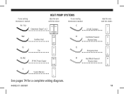
if your existing thermostat is marked: HEAT PUMP SYSTEMS label the wire with this sticker: if your existing thermostat is marked: label the wire with this sticker: Y1 / Y2 Compressor Stage 1 or 2 Y1 Y2 Y2 Y1 C 24 VAC Common C C O W2 Auxilliary Heat W2 W2 O Cool Mode Powered Reverse Valve O G Fan G G E Emergency Heat E E R/RC R / RC 24 VAC Power Supply R/RC B B Heat Mode Powered Reverse Valve B L L System Monitor L See pages 74 for a complete wiring diagram. 44002-01 r051807 11
if your existing thermostat is marked: HEAT PUMP SYSTEMS label the wire with this sticker: if your existing thermostat is marked: label the wire with this sticker: Y1 / Y2 Compressor Stage 1 or 2 Y1 Y2 Y2 Y1 C 24 VAC Common C C O W2 Auxilliary Heat W2 W2 O Cool Mode Powered Reverse Valve O G Fan G G E Emergency Heat E E R/RC R / RC 24 VAC Power Supply R/RC B B Heat Mode Powered Reverse Valve B L L System Monitor L See pages 74 for a complete wiring diagram. 44002-01 r051807 11

Owner's Manual
Page 75
Not all terminals need to be connected. • Add jumper between W2 and E terminals on the heat pump system requirement. RC/R C Y1 Heat Pump Systems Optional Jumper Y2 W2 E O B G L 24VAC Supply Compressor Compressor Auxiliary Emergency Reversing Valve Reversing Valve Fan System Stage 1 Stage 2 Heat Heat Cool Heat Control Monitor 24VAC Common (if available) Number of wires connected depends on systems without an E wire. 74 44002-01 r051807
Not all terminals need to be connected. • Add jumper between W2 and E terminals on the heat pump system requirement. RC/R C Y1 Heat Pump Systems Optional Jumper Y2 W2 E O B G L 24VAC Supply Compressor Compressor Auxiliary Emergency Reversing Valve Reversing Valve Fan System Stage 1 Stage 2 Heat Heat Cool Heat Control Monitor 24VAC Common (if available) Number of wires connected depends on systems without an E wire. 74 44002-01 r051807


