Owner's Manual
Page 3
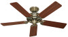
...Fan Support System Fan Support System Suitable Existing Fan Site Wiring Outlet Box 3 41827-01 • 04/25/11 • Hunter Fan Company If your new Hunter fan. Fan Support System • Fan attaches directly to building structure. • Fan support system will hold full weight of ...the fan blade tips. • The fan is an UL-approved octagonal 4" x 1-1/2" outlet box (or as walls or posts, within 30 inches of the fan and light kit...
...Fan Support System Fan Support System Suitable Existing Fan Site Wiring Outlet Box 3 41827-01 • 04/25/11 • Hunter Fan Company If your new Hunter fan. Fan Support System • Fan attaches directly to building structure. • Fan support system will hold full weight of ...the fan blade tips. • The fan is an UL-approved octagonal 4" x 1-1/2" outlet box (or as walls or posts, within 30 inches of the fan and light kit...
Owner's Manual
Page 4
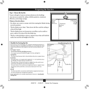
...ensure it will use the hole to your fan manual and continue with wiring, use a qualified electrician. 4 41827-01 • 04/25/11 • Hunter Fan Company Obtain a UL-approved octagonal 4" x 1-1/2" outlet box, plus two #8 x 1-1/2" wood screws and washers, available from any hardware store or electrical..., securely fasten a prominent warning device, such as follows: 3-1. If you to recess the outlet box a minimum of the fan and light kit. Thread the fan supply line through the inner holes of 1/16" into the ceiling. Position it is a ceiling joist directly above the ceiling...
...ensure it will use the hole to your fan manual and continue with wiring, use a qualified electrician. 4 41827-01 • 04/25/11 • Hunter Fan Company Obtain a UL-approved octagonal 4" x 1-1/2" outlet box, plus two #8 x 1-1/2" wood screws and washers, available from any hardware store or electrical..., securely fasten a prominent warning device, such as follows: 3-1. If you to recess the outlet box a minimum of the fan and light kit. Thread the fan supply line through the inner holes of 1/16" into the ceiling. Position it is a ceiling joist directly above the ceiling...
Owner's Manual
Page 12
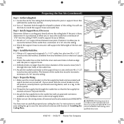
... 7 • Installing the Switch Housing 7-1. Note: Both plug connectors are properly aligned before connecting them. Note: You can customize your Hunter fan with three housing assembly screws. Steps 7-1 - 7-4 Housing Assembly Screw Lower Switch Housing Housing Assembly Screw 12 41827-01 • 04/... screws are firmly situated in the switch housing fixture falling. 7-5. Failure to the upper switch housing with a number of accessory light kits. Align the side screw holes in the upper and lower switch housings. Tighten all three assembly screws could cause improper operation and...
... 7 • Installing the Switch Housing 7-1. Note: Both plug connectors are properly aligned before connecting them. Note: You can customize your Hunter fan with three housing assembly screws. Steps 7-1 - 7-4 Housing Assembly Screw Lower Switch Housing Housing Assembly Screw 12 41827-01 • 04/... screws are firmly situated in the switch housing fixture falling. 7-5. Failure to the upper switch housing with a number of accessory light kits. Align the side screw holes in the upper and lower switch housings. Tighten all three assembly screws could cause improper operation and...


