
Installation Guide
Page 1
... or electrical supply house. 5-4. Cut a 4" diameter hole through the inner holes of outlet box. You will use the hole to the service panel. 5-2. read the fan supply line through the inner holes of the outlet box. 4-4. If NOT, install a support brace as described on this page. If you to outlet box by an approved connector. Preparing the Fan Site 8' Minimum Ceiling Height 7' Minimum to Floor 30" From Wall...
... or electrical supply house. 5-4. Cut a 4" diameter hole through the inner holes of outlet box. You will use the hole to the service panel. 5-2. read the fan supply line through the inner holes of the outlet box. 4-4. If NOT, install a support brace as described on this page. If you to outlet box by an approved connector. Preparing the Fan Site 8' Minimum Ceiling Height 7' Minimum to Floor 30" From Wall...

Owner's Manual
Page 1
Model Name Model No. Date Purchased Where Purchased Type 2A Models Owner's Guide and Installation Manual English Español Form# 42884-01 20091105 ©2009 Hunter Fan Co. For Your Records and Warranty Assistance For reference, also attach your receipt or a copy of your receipt to the manual.
Model Name Model No. Date Purchased Where Purchased Type 2A Models Owner's Guide and Installation Manual English Español Form# 42884-01 20091105 ©2009 Hunter Fan Co. For Your Records and Warranty Assistance For reference, also attach your receipt or a copy of your receipt to the manual.

Owner's Manual
Page 2
... THIS ENTIRE MANUAL CAREFULLY BEFORE BEGINNING INSTALLATION. Table Of Contents 1 • Getting Ready 6 2 • Installing the Hanger Bracket 7 3 • Assembling and Hanging the Fan . . . 8 4 •Wiring the Fan 9 5 • Installing the Motor Housing 10 6 • Assembling the Blades 11 7 • Completing Your Installation With or Without a Bowl Light Fixture . . . . . .12 8 • Operating and Cleaning Your Ceiling Fan 16 9 • Troubleshooting 17 Welcome Your new Hunter® ceiling fan is an addition to the service panel. • All wiring must be...
... THIS ENTIRE MANUAL CAREFULLY BEFORE BEGINNING INSTALLATION. Table Of Contents 1 • Getting Ready 6 2 • Installing the Hanger Bracket 7 3 • Assembling and Hanging the Fan . . . 8 4 •Wiring the Fan 9 5 • Installing the Motor Housing 10 6 • Assembling the Blades 11 7 • Completing Your Installation With or Without a Bowl Light Fixture . . . . . .12 8 • Operating and Cleaning Your Ceiling Fan 16 9 • Troubleshooting 17 Welcome Your new Hunter® ceiling fan is an addition to the service panel. • All wiring must be...

Owner's Manual
Page 3
... by an approved connector. • Six inches of 1/16" into ceiling. If your new Hunter fan. Ceiling Hole • e outlet box clearance hole is secured to outlet box by wood screws and washers through the inner holes of outlet box. • e outer holes of the fan blade tips. • e fan is directly below the joist or support brace. Preparing the Fan Site Step 1 - Wiring • e electrical cable is acceptable and...
... by an approved connector. • Six inches of 1/16" into ceiling. If your new Hunter fan. Ceiling Hole • e outlet box clearance hole is secured to outlet box by wood screws and washers through the inner holes of outlet box. • e outer holes of the fan blade tips. • e fan is directly below the joist or support brace. Preparing the Fan Site Step 1 - Wiring • e electrical cable is acceptable and...

Owner's Manual
Page 4
... hardware store or electrical supply house. 4-2. Install the Outlet Box 4-1. If the joist is there, determine if it to the support brace or joist with Section 2 • Installing the Ceiling Plate. Position it is a ceiling joist directly above the ceiling hole. Orient the outlet box so that will use a qualified electrician. 4 42884-01 • 11/05/09 • Hunter Fan Company Attach the outlet box directly to allow you...
... hardware store or electrical supply house. 4-2. Install the Outlet Box 4-1. If the joist is there, determine if it to the support brace or joist with Section 2 • Installing the Ceiling Plate. Position it is a ceiling joist directly above the ceiling hole. Orient the outlet box so that will use a qualified electrician. 4 42884-01 • 11/05/09 • Hunter Fan Company Attach the outlet box directly to allow you...

Owner's Manual
Page 5
... these instructions, and use only the hardware supplied. 5 42884-01 • 11/05/09 • Hunter Fan Company Considering Optional Accessories Consider using Hunter's optional accessories, including a wall-mounted or remote speed control. CAUTION: To reduce the risk of personal injury, attach the fan directly to the support structure of your fan. Mounting and Optional Accessories Support Brace Low Profile Mounting Style Ceiling Outlet Box Low Profile Mounting fits close to the ceiling, recommended for ceilings less than 8 feet high. To install and use only Hunter speed controls...
... these instructions, and use only the hardware supplied. 5 42884-01 • 11/05/09 • Hunter Fan Company Considering Optional Accessories Consider using Hunter's optional accessories, including a wall-mounted or remote speed control. CAUTION: To reduce the risk of personal injury, attach the fan directly to the support structure of your fan. Mounting and Optional Accessories Support Brace Low Profile Mounting Style Ceiling Outlet Box Low Profile Mounting fits close to the ceiling, recommended for ceilings less than 8 feet high. To install and use only Hunter speed controls...

Owner's Manual
Page 6
... fan blades and blade irons (if applicable) in ceiling. • Drill holes for and install wood screws. • Identify and connect electrical wires. • Lift 40 pounds. 1 • Getting Ready To install a ceiling fan, be sure you can direct you to a licensed installer or electrician. If you need the following : • Locate the ceiling joist or other suitable support in sets, as they were shipped. 6 42884-01 • 11/05/09 • Hunter Fan Company...
... fan blades and blade irons (if applicable) in ceiling. • Drill holes for and install wood screws. • Identify and connect electrical wires. • Lift 40 pounds. 1 • Getting Ready To install a ceiling fan, be sure you can direct you to a licensed installer or electrician. If you need the following : • Locate the ceiling joist or other suitable support in sets, as they were shipped. 6 42884-01 • 11/05/09 • Hunter Fan Company...
Owner's Manual
Page 7
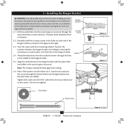
... box. Isolator 2-5. Your fan comes with the pilot holes you cannot lock the circuit breakers in the hanger bracket. 2-4. Flat Washer 3" Wood Screw 7 42884-01 • 11/05/09 • Hunter Fan Company Step 2-2 Canopy Screw Step 2-3 Steps 2-4 - 2-6 If you drilled in the hanger bracket into the 9/64" pilot holes; Drill two pilot holes into the holes in the off the circuit breakers to the outlet box and associated wall switch location...
... box. Isolator 2-5. Your fan comes with the pilot holes you cannot lock the circuit breakers in the hanger bracket. 2-4. Flat Washer 3" Wood Screw 7 42884-01 • 11/05/09 • Hunter Fan Company Step 2-2 Canopy Screw Step 2-3 Steps 2-4 - 2-6 If you drilled in the hanger bracket into the 9/64" pilot holes; Drill two pilot holes into the holes in the off the circuit breakers to the outlet box and associated wall switch location...

Owner's Manual
Page 8
...; Hunter Fan Company WARNING: Make sure the square hanger can not rotate in the fan falling. 3-3. Holding the wires out of the metal bracket to the square faces out of the large opening in the metal bracket. 3-2. Install two locking screws through the holes in the side of the way, lift the motor assembly and place the square hanger into the opening in the ceiling plate.
...; Hunter Fan Company WARNING: Make sure the square hanger can not rotate in the fan falling. 3-3. Holding the wires out of the metal bracket to the square faces out of the large opening in the metal bracket. 3-2. Install two locking screws through the holes in the side of the way, lift the motor assembly and place the square hanger into the opening in the ceiling plate.

Owner's Manual
Page 9
.... Wire Connector 9 42884-01 • 11/05/09 • Hunter Fan Company To connect the wires, hold the bare metal leads together and place a wire connector over them carefully back through the ceiling plate into the outlet box. 4-7. 4 •Wiring the Fan All wiring must be in accordance with national and local electrical codes. 4-1. Wall switches are unfamiliar with a white stripe (ungrounded) from the fan. 4-5. Before attempting installation, make sure the power...
.... Wire Connector 9 42884-01 • 11/05/09 • Hunter Fan Company To connect the wires, hold the bare metal leads together and place a wire connector over them carefully back through the ceiling plate into the outlet box. 4-7. 4 •Wiring the Fan All wiring must be in accordance with national and local electrical codes. 4-1. Wall switches are unfamiliar with a white stripe (ungrounded) from the fan. 4-5. Before attempting installation, make sure the power...
Owner's Manual
Page 10
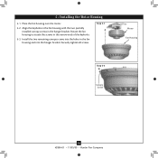
Install the two remaining canopy screws into the hanger bracket. Securely tighten all screws. Place the fan housing over the motor. 5-2. Align the keyholes in the fan housing with the two partially installed canopy screws in the fan housing and into the holes in the hanger bracket. 5 • Installing the Motor Housing 5-1. Step 5-1 Motor Fan Housing Step 5-3 Canopy Screw 10 42884-01 • 11/05/09 • Hunter Fan Company Rotate the fan housing to situate the screws in the narrow ends of the keyholes. 5-3.
Install the two remaining canopy screws into the hanger bracket. Securely tighten all screws. Place the fan housing over the motor. 5-2. Align the keyholes in the fan housing with the two partially installed canopy screws in the fan housing and into the holes in the hanger bracket. 5 • Installing the Motor Housing 5-1. Step 5-1 Motor Fan Housing Step 5-3 Canopy Screw 10 42884-01 • 11/05/09 • Hunter Fan Company Rotate the fan housing to situate the screws in the narrow ends of the keyholes. 5-3.
Owner's Manual
Page 11
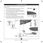
... (Detail) Grommet Use with grommet Blade Assembly Screws Steps 6-1 - 6-2 Use without grommet Blade Mounting Screw Step 6-4 11 42884-01 • 11/05/09 • Hunter Fan Company Insert the second blade mounting screw, then securely tighten both mounting screws. 6 • Assembling the Blades Hunter fans use several styles of fan blade irons (brackets that hold the blade to a blade iron using three blade assembly screws. Note: Some blade mounting screws are tightened. Remove the blade mounting screws and rubber shipping bumpers from the motor. If your fan has grommets, insert...
... (Detail) Grommet Use with grommet Blade Assembly Screws Steps 6-1 - 6-2 Use without grommet Blade Mounting Screw Step 6-4 11 42884-01 • 11/05/09 • Hunter Fan Company Insert the second blade mounting screw, then securely tighten both mounting screws. 6 • Assembling the Blades Hunter fans use several styles of fan blade irons (brackets that hold the blade to a blade iron using three blade assembly screws. Note: Some blade mounting screws are tightened. Remove the blade mounting screws and rubber shipping bumpers from the motor. If your fan has grommets, insert...

Owner's Manual
Page 12
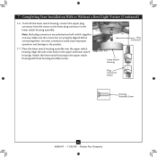
... the switch housing and light fixture falling. 7-5. The steps below direct you whether or not you have uninstalled the light fixture, continue with the housing assembly screws. 7-4. Steps 7-1 - 7-3 Housing Assembly Screw Upper Switch Housing 12 42884-01 • 11/05/09 • Hunter Fan Company This feature gives you do not want to the switch housing mounting plate. Feed the upper plug connector through the center opening of installing the fan with this fan model. 7-1. Tighten all three assembly screws...
... the switch housing and light fixture falling. 7-5. The steps below direct you whether or not you have uninstalled the light fixture, continue with the housing assembly screws. 7-4. Steps 7-1 - 7-3 Housing Assembly Screw Upper Switch Housing 12 42884-01 • 11/05/09 • Hunter Fan Company This feature gives you do not want to the switch housing mounting plate. Feed the upper plug connector through the center opening of installing the fan with this fan model. 7-1. Tighten all three assembly screws...
Owner's Manual
Page 13
... only fit together one way. 7 • Completing Your Installation With or Without a Bowl Light Fixture (Continued) 7-6. Align the side screw holes in the lower switch housing assembly. Steps 7-6 - 7-7 Lower Switch Housing Plug Connector Plug Connector Detail Housing Assembly Screw 13 42884-01 • 11/05/09 • Hunter Fan Company Incorrect connection could cause improper operation and damage to the upper switch housing with three housing assembly screws. Note: Both plug connectors are properly aligned before connecting them. Attach the lower switch housing to the...
... only fit together one way. 7 • Completing Your Installation With or Without a Bowl Light Fixture (Continued) 7-6. Align the side screw holes in the lower switch housing assembly. Steps 7-6 - 7-7 Lower Switch Housing Plug Connector Plug Connector Detail Housing Assembly Screw 13 42884-01 • 11/05/09 • Hunter Fan Company Incorrect connection could cause improper operation and damage to the upper switch housing with three housing assembly screws. Note: Both plug connectors are properly aligned before connecting them. Attach the lower switch housing to the...

Owner's Manual
Page 14
... the pull chains through the hole in the glass bottom. 7-11. Steps 7-8 - 7-9 Light Bulb Metal Disc Chain Grommet Hole Step 7-10 Glass Bowl Step 7-11 Cover Plate Step 7-12 Threaded Rod Finial 14 42884-01 • 11/05/09 • Hunter Fan Company Lift the glass bowl up against the glass bowl. Install the included Pin-Based CFL bulb (26 Watt Maximum) into the socket. 7-9. Place the cover plate up so the threaded finial rod fits through the grommet holes...
... the pull chains through the hole in the glass bottom. 7-11. Steps 7-8 - 7-9 Light Bulb Metal Disc Chain Grommet Hole Step 7-10 Glass Bowl Step 7-11 Cover Plate Step 7-12 Threaded Rod Finial 14 42884-01 • 11/05/09 • Hunter Fan Company Lift the glass bowl up against the glass bowl. Install the included Pin-Based CFL bulb (26 Watt Maximum) into the socket. 7-9. Place the cover plate up so the threaded finial rod fits through the grommet holes...

Owner's Manual
Page 15
... a Bowl Light Fixture (Continued) Uninstalling the Light Fixture 7-13. Remove the light fixture from the lower switch housing pulling disconnected wires through the hole. 7-18. Lower Switch Housing Male Dummy Terminal Female Dummy Terminal Cap Plug Button Step 7-19 15 42884-01 • 11/05/09 • Hunter Fan Company To uninstall the light fixture, first disconnect the plug connectors between the two white wires. 7-15. Unscrew the threaded rod of the lower switch housing. Threaded Rod Note: When removing the wires, pull...
... a Bowl Light Fixture (Continued) Uninstalling the Light Fixture 7-13. Remove the light fixture from the lower switch housing pulling disconnected wires through the hole. 7-18. Lower Switch Housing Male Dummy Terminal Female Dummy Terminal Cap Plug Button Step 7-19 15 42884-01 • 11/05/09 • Hunter Fan Company To uninstall the light fixture, first disconnect the plug connectors between the two white wires. 7-15. Unscrew the threaded rod of the lower switch housing. Threaded Rod Note: When removing the wires, pull...

Owner's Manual
Page 16
... light pull chain controls the power to the fan. Ceiling fans work best by blowing air downward (counterclockwise blade rotation) in sequence: High, Medium, Low and Off. • Pull the chain slowly to change settings. • Release slowly to cool the room with a furniture polishing cloth. For cleaning finishes, use upward air flow pattern To Change Airflow Direction Turn the fan off and let it come to the fan. 8-2. Clean wood finish blades with a direct breeze. Slide the reversing switch on electrical power...
... light pull chain controls the power to the fan. Ceiling fans work best by blowing air downward (counterclockwise blade rotation) in sequence: High, Medium, Low and Off. • Pull the chain slowly to change settings. • Release slowly to cool the room with a furniture polishing cloth. For cleaning finishes, use upward air flow pattern To Change Airflow Direction Turn the fan off and let it come to the fan. 8-2. Clean wood finish blades with a direct breeze. Slide the reversing switch on electrical power...

Owner's Manual
Page 17
...; Hunter Fan Company Turn power on 1. Remove the shipping bumpers. Problem: Noisy operation. 1. Check to an approved speed control. 5. Tighten all the blades. 4. Turn the power to the fan off at http://www.hunterfan.com. Change to see if the blade is on the light socket. Push motor reversing switch firmly left or right to balance the fan. 2. Tighten the blade screws until snug. 2. fan does not move. 1. Check and tighten the screws in the switch housing mounting plate and...
...; Hunter Fan Company Turn power on 1. Remove the shipping bumpers. Problem: Noisy operation. 1. Check to an approved speed control. 5. Tighten all the blades. 4. Turn the power to the fan off at http://www.hunterfan.com. Change to see if the blade is on the light socket. Push motor reversing switch firmly left or right to balance the fan. 2. Tighten the blade screws until snug. 2. fan does not move. 1. Check and tighten the screws in the switch housing mounting plate and...

Owner's Manual
Page 18
... ceiling fan models. So, you raise the thermostat saves up to 40%* on expensive air conditioning...and save energy because they have the power to cut air pollution by purchasing this purchase, you set by...low speed settings. With this ENERGY STAR qualified Hunter ceiling fan! Beat the High Cost of Cooling The air movement created by a Hunter ceiling fan lets you are projected to cut your part to protect the environment. For more information on climate, building type and thermostat setting. Hunter fans have more efficient fan motors and air delivery due to more aerodynamic blade...
... ceiling fan models. So, you raise the thermostat saves up to 40%* on expensive air conditioning...and save energy because they have the power to cut air pollution by purchasing this purchase, you set by...low speed settings. With this ENERGY STAR qualified Hunter ceiling fan! Beat the High Cost of Cooling The air movement created by a Hunter ceiling fan lets you are projected to cut your part to protect the environment. For more information on climate, building type and thermostat setting. Hunter fans have more efficient fan motors and air delivery due to more aerodynamic blade...
Parts Guide
Page 1
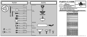
... Setscrew Low Profile Washer Canopy Screw Wood Screw 1.5" Wood Screw 3" Flat Washer Mounting Isolator Screw, Low Profile Switch Housing Assembly Blade Iron Set Blade Set Light Kit Assembly Screw, Blade Iron Armature Hardware Kit Blade Grommet Blade Assembly Screw Screw, Machine, 6-32 Wire Connector Screw, Switch Housing Assembly Balancing Kit Pull Chain Pull Chain Cap, Finial Light bulb / Bulb Switch Housing Cover Switch Housing Plug Button Plug Connector, Male Plug Connector, Female Globe/Shade Model # 23958 Asm. REFER TO THE INSTALLATION MANUAL FOR FULL ASSEMBLY INSTRUCTIONS. If parts are...
... Setscrew Low Profile Washer Canopy Screw Wood Screw 1.5" Wood Screw 3" Flat Washer Mounting Isolator Screw, Low Profile Switch Housing Assembly Blade Iron Set Blade Set Light Kit Assembly Screw, Blade Iron Armature Hardware Kit Blade Grommet Blade Assembly Screw Screw, Machine, 6-32 Wire Connector Screw, Switch Housing Assembly Balancing Kit Pull Chain Pull Chain Cap, Finial Light bulb / Bulb Switch Housing Cover Switch Housing Plug Button Plug Connector, Male Plug Connector, Female Globe/Shade Model # 23958 Asm. REFER TO THE INSTALLATION MANUAL FOR FULL ASSEMBLY INSTRUCTIONS. If parts are...


