
Installation Guide
Page 1
... Box 4-1. Fan Support System o Fan attaches directly to building structure. You will hold the outlet box and the full weight of the ceiling. For instructions to install your ceiling fan, go to your new Hunter fan. Outlet Box o e outlet box is acceptable and safe for safety, reliable operation, maximum efficiency, and energy savings. Wiring o e electrical cable is recessed a minimum of lead wires extend from any hardware store or electrical supply house. 5-4. Ceiling Hole...
... Box 4-1. Fan Support System o Fan attaches directly to building structure. You will hold the outlet box and the full weight of the ceiling. For instructions to install your ceiling fan, go to your new Hunter fan. Outlet Box o e outlet box is acceptable and safe for safety, reliable operation, maximum efficiency, and energy savings. Wiring o e electrical cable is recessed a minimum of lead wires extend from any hardware store or electrical supply house. 5-4. Ceiling Hole...

Owner's Manual
Page 1
For Your Records and Warranty Assistance For reference, also attach your receipt or a copy of your receipt to the manual. Date Purchased Where Purchased Type 2A Models Owner's Guide and Installation Manual English Español Form# 42882-01 20101214 ©2010 Hunter Fan Co. Model Name Model No.
For Your Records and Warranty Assistance For reference, also attach your receipt or a copy of your receipt to the manual. Date Purchased Where Purchased Type 2A Models Owner's Guide and Installation Manual English Español Form# 42882-01 20101214 ©2010 Hunter Fan Co. Model Name Model No.
Owner's Manual
Page 2
...; Installing the Hanger Bracket 7 3 • Assembling and Hanging the Fan . . . . 8 4 •Wiring the Fan 9 5 • Installing the Motor Housing 10 6 • Assembling the Blades 11 7 • Completing Your Installation With a Multi Staked Light Fixture 12 8 • Operating and Cleaning Your Ceiling Fan 14 9 • Troubleshooting 15 Before installing your fan, for your fan. Use only Hunter speed controls. • This product conforms to UL STD 507 and is complete. © 2010 Hunter Fan Company 2 42882-01 • 12/14/10 • Hunter Fan Company...
...; Installing the Hanger Bracket 7 3 • Assembling and Hanging the Fan . . . . 8 4 •Wiring the Fan 9 5 • Installing the Motor Housing 10 6 • Assembling the Blades 11 7 • Completing Your Installation With a Multi Staked Light Fixture 12 8 • Operating and Cleaning Your Ceiling Fan 14 9 • Troubleshooting 15 Before installing your fan, for your fan. Use only Hunter speed controls. • This product conforms to UL STD 507 and is complete. © 2010 Hunter Fan Company 2 42882-01 • 12/14/10 • Hunter Fan Company...
Owner's Manual
Page 3
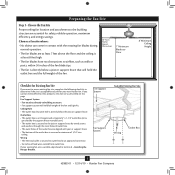
... existing fan site is directly below a joist or support brace that will hold the outlet box and the full weight of 1/16" into ceiling. Fan Support System Fan Support System Suitable Existing Fan Site Wiring Outlet Box 3 42882-01 • 12/14/10 • Hunter Fan Company Preparing the Fan Site Step 1 - Choose the Fan Site Proper ceiling fan location and attachment to Section 2 • Installing the Hanger Bracket. Wiring • e electrical cable is directly below...
... existing fan site is directly below a joist or support brace that will hold the outlet box and the full weight of 1/16" into ceiling. Fan Support System Fan Support System Suitable Existing Fan Site Wiring Outlet Box 3 42882-01 • 12/14/10 • Hunter Fan Company Preparing the Fan Site Step 1 - Choose the Fan Site Proper ceiling fan location and attachment to Section 2 • Installing the Hanger Bracket. Wiring • e electrical cable is directly below...
Owner's Manual
Page 4
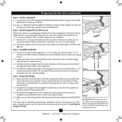
.../14/10 • Hunter Fan Company Step 3 - If NOT, install a support brace as a tag, to recess the outlet box a minimum of the ceiling. Steps 2 - 3 3-2. Prepare the Wiring 5-1. Cut a 4" diameter hole through the inner holes of the outlet box. 4-4. Obtain a UL-approved octagonal 4" x 1-1/2" outlet box, plus two #8 x 1-1/2" wood screws and washers, available from any hardware store or electrical supply house. 5-4. If you to the service panel. 5-2. read...
.../14/10 • Hunter Fan Company Step 3 - If NOT, install a support brace as a tag, to recess the outlet box a minimum of the ceiling. Steps 2 - 3 3-2. Prepare the Wiring 5-1. Cut a 4" diameter hole through the inner holes of the outlet box. 4-4. Obtain a UL-approved octagonal 4" x 1-1/2" outlet box, plus two #8 x 1-1/2" wood screws and washers, available from any hardware store or electrical supply house. 5-4. If you to the service panel. 5-2. read...
Owner's Manual
Page 5
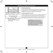
... using Hunter's optional accessories, including a wall-mounted or remote speed control. For quiet and optimum performance of the building according to these instructions, and use the accessories, follow the instructions included with each product. CAUTION: To reduce the risk of personal injury, attach the fan directly to the support structure of your fan. Mounting and Optional Accessories Support Brace Low Profile Mounting Style Ceiling Outlet Box Low Profile Mounting fits close to the ceiling, recommended for ceilings less than 8 feet high...
... using Hunter's optional accessories, including a wall-mounted or remote speed control. For quiet and optimum performance of the building according to these instructions, and use the accessories, follow the instructions included with each product. CAUTION: To reduce the risk of personal injury, attach the fan directly to the support structure of your fan. Mounting and Optional Accessories Support Brace Low Profile Mounting Style Ceiling Outlet Box Low Profile Mounting fits close to the ceiling, recommended for ceilings less than 8 feet high...
Owner's Manual
Page 6
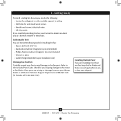
... Canada, call 1-866-268-1936). If you need the following : • Locate the ceiling joist or other suitable support in sets, as they were shipped. 6 42882-01 • 12/14/10 • Hunter Fan Company Refer to the included Parts Guide. If any shipping damage to the motor or fan blades. Installing Multiple Fans? 1 • Getting Ready To install a ceiling fan, be sure you can direct you to a licensed installer or electrician.
... Canada, call 1-866-268-1936). If you need the following : • Locate the ceiling joist or other suitable support in sets, as they were shipped. 6 42882-01 • 12/14/10 • Hunter Fan Company Refer to the included Parts Guide. If any shipping damage to the motor or fan blades. Installing Multiple Fans? 1 • Getting Ready To install a ceiling fan, be sure you can direct you to a licensed installer or electrician.
Owner's Manual
Page 7
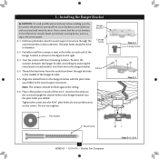
... service panel. 2-1. Isolator 2-5. Tighten the screws into the wood support structure through the hole in the off the circuit breakers to the outlet box and associated wall switch location. Position the isolators between the hanger bracket and ceiling by turning off position, securely fasten a prominent warning device, such as shown in the outlet box. Do not over tighten. 2 • Installing the Hanger Bracket CAUTION: To avoid possible electrical...
... service panel. 2-1. Isolator 2-5. Tighten the screws into the wood support structure through the hole in the off the circuit breakers to the outlet box and associated wall switch location. Position the isolators between the hanger bracket and ceiling by turning off position, securely fasten a prominent warning device, such as shown in the outlet box. Do not over tighten. 2 • Installing the Hanger Bracket CAUTION: To avoid possible electrical...
Owner's Manual
Page 8
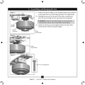
... faces out of the large opening in the side of the way, lift the motor assembly and place the square hanger into the opening in the metal bracket. 3-2. Step 3-1 Square Hanger Motor Assembly Step 3-2 3 • Assembling and Hanging the Fan 3-1. Green Ground Wire Step 3-3 Green Ground Wire #8-32 x 1" Screw Locking Screw 8 42882-01 • 12/14/10 • Hunter Fan Company Install two locking screws through the holes in the ceiling plate.
... faces out of the large opening in the side of the way, lift the motor assembly and place the square hanger into the opening in the metal bracket. 3-2. Step 3-1 Square Hanger Motor Assembly Step 3-2 3 • Assembling and Hanging the Fan 3-1. Green Ground Wire Step 3-3 Green Ground Wire #8-32 x 1" Screw Locking Screw 8 42882-01 • 12/14/10 • Hunter Fan Company Install two locking screws through the holes in the ceiling plate.
Owner's Manual
Page 9
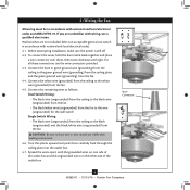
...: Dual Switch Wiring: • The black wire (ungrounded) from the ceiling to the black wire (ungrounded) from the fan • The black/white wire (ungrounded) from the fan to the wire (ungrounded) for the wall switch Single Switch Wiring: • The black wire (ungrounded) from the ceiling to the white wire (grounded) from the fan. 4-4. Wire Connector 9 42882-01 • 12/14/10 • Hunter Fan Company Spread the wires apart, with national and local electrical codes. 4-1. 4 •Wiring the Fan All wiring...
...: Dual Switch Wiring: • The black wire (ungrounded) from the ceiling to the black wire (ungrounded) from the fan • The black/white wire (ungrounded) from the fan to the wire (ungrounded) for the wall switch Single Switch Wiring: • The black wire (ungrounded) from the ceiling to the white wire (grounded) from the fan. 4-4. Wire Connector 9 42882-01 • 12/14/10 • Hunter Fan Company Spread the wires apart, with national and local electrical codes. 4-1. 4 •Wiring the Fan All wiring...
Owner's Manual
Page 10
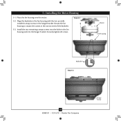
Align the keyholes in the fan housing with the two partially installed canopy screws in the fan housing and into the hanger bracket. Securely tighten all screws. 5 • Installing the Motor Housing 5-1. Install the two remaining canopy screws into the holes in the hanger bracket. Step 5-1 Motor Fan Housing Keyhole Step 5-3 10 42882-01 • 12/14/10 • Hunter Fan Company Canopy Screw Rotate the fan housing to situate the screws in the narrow ends of the keyholes. 5-3. Place the fan housing over the motor. 5-2.
Align the keyholes in the fan housing with the two partially installed canopy screws in the fan housing and into the hanger bracket. Securely tighten all screws. 5 • Installing the Motor Housing 5-1. Install the two remaining canopy screws into the holes in the hanger bracket. Step 5-1 Motor Fan Housing Keyhole Step 5-3 10 42882-01 • 12/14/10 • Hunter Fan Company Canopy Screw Rotate the fan housing to situate the screws in the narrow ends of the keyholes. 5-3. Place the fan housing over the motor. 5-2.

Owner's Manual
Page 11
... after screws are installed in the motor to a blade iron using three blade assembly screws. Remove the blade mounting screws and rubber shipping bumpers from the motor. Use a dry or slightly damp lint free cloth to the fan. If your fan has grommets, insert them by hand into the holes on the blades. This is normal. 6-3. For each blade to secure shipping blocks. 6-4. Step 6-1 (Detail) Grommet Note: The blades on this fan have been treated with grommet Blade Assembly Screws Step 6-4 Use without grommet...
... after screws are installed in the motor to a blade iron using three blade assembly screws. Remove the blade mounting screws and rubber shipping bumpers from the motor. Use a dry or slightly damp lint free cloth to the fan. If your fan has grommets, insert them by hand into the holes on the blades. This is normal. 6-3. For each blade to secure shipping blocks. 6-4. Step 6-1 (Detail) Grommet Note: The blades on this fan have been treated with grommet Blade Assembly Screws Step 6-4 Use without grommet...
Owner's Manual
Page 12
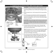
... and lower switch housings. Steps 7-1 - 7-3 Housing Assembly Screw Upper Switch Housing CAUTION: Make sure the upper switch housing is securely attached to the product. 7-5. Place the lower switch housing assembly over the upper switch housing. Align the side screw holes in the narrow end of the keyhole slots. 7 • Completing Your Installation With a Multi Staked Light Fixture WARNING: Use only the light fixture supplied with this fan model. 7-1. To attach the lower switch housing, connect the upper plug connector from the motor to...
... and lower switch housings. Steps 7-1 - 7-3 Housing Assembly Screw Upper Switch Housing CAUTION: Make sure the upper switch housing is securely attached to the product. 7-5. Place the lower switch housing assembly over the upper switch housing. Align the side screw holes in the narrow end of the keyhole slots. 7 • Completing Your Installation With a Multi Staked Light Fixture WARNING: Use only the light fixture supplied with this fan model. 7-1. To attach the lower switch housing, connect the upper plug connector from the motor to...
Owner's Manual
Page 13
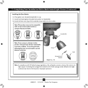
... a Multi Staked Light Fixture (Continued) Installing the Glass Shades 7-6. Note: This product may result in cup. 7-7. Lampholder Note: If you connect a dimmer to this product, the pull chain dimmer will disable to this ceiling fan contains a device that restricts its light output. Exceeding the wattage limit marked on lampholder. 7-8. Bulb Threaded lock Washer Steps 7-6 - 7-8 Note: In compliance with certain remote/wall controls or compact fluorescent bulbs. Install 60 Watt max (Type B10) candelabra...
... a Multi Staked Light Fixture (Continued) Installing the Glass Shades 7-6. Note: This product may result in cup. 7-7. Lampholder Note: If you connect a dimmer to this product, the pull chain dimmer will disable to this ceiling fan contains a device that restricts its light output. Exceeding the wattage limit marked on lampholder. 7-8. Bulb Threaded lock Washer Steps 7-6 - 7-8 Note: In compliance with certain remote/wall controls or compact fluorescent bulbs. Install 60 Watt max (Type B10) candelabra...
Owner's Manual
Page 14
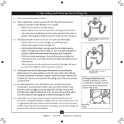
The fan pull chain controls power to clean the blades. If this fan have been treated with a direct breeze. For cleaning finishes, use upward air flow pattern To Change Airflow Direction Turn the fan off and let it come to a complete stop. Remove surface smudges or accumulated dirt and dust using a mild detergent and a slightly dampened cloth. Restart fan. 8-6. The light varies from recoiling into the connector. 8-3. Release the chain when the desired...
The fan pull chain controls power to clean the blades. If this fan have been treated with a direct breeze. For cleaning finishes, use upward air flow pattern To Change Airflow Direction Turn the fan off and let it come to a complete stop. Remove surface smudges or accumulated dirt and dust using a mild detergent and a slightly dampened cloth. Restart fan. 8-6. The light varies from recoiling into the connector. 8-3. Release the chain when the desired...

Owner's Manual
Page 15
... switch housing mounting plate and in the upper and lower switch housing. If you need parts or service assistance, please call 888‑830‑1326 (In Canada, call 1-866-268-1936) or visit us at our Web site at the wall switch. Pull the pull chain to ensure it is engaged. 5. Turn power on . 6. Remove the shipping bumpers. Tighten the blade bracket screws until snug. 3. CFL light bulbs are installed meet the specifications on the MAX wattage...
... switch housing mounting plate and in the upper and lower switch housing. If you need parts or service assistance, please call 888‑830‑1326 (In Canada, call 1-866-268-1936) or visit us at our Web site at the wall switch. Pull the pull chain to ensure it is engaged. 5. Turn power on . 6. Remove the shipping bumpers. Tighten the blade bracket screws until snug. 3. CFL light bulbs are installed meet the specifications on the MAX wattage...

Parts Guide
Page 1
Parts List Item Name Ceiling Plate Motor Housing Housing Cover Screw Wood Screw 1.5" Wood Screw 3" Locking Screw Flat Washer Mounting Isolator Light Kit Assembly Globe/Shade Light bulb / Bulb Blade Iron Set Blade Set Screw, Blade Iron Armature Hardware Kit Blade Grommet Blade Assembly Screw Screw, Machine, 6-32 Wire Connector Screw, Switch Housing Assembly Pull Chain Pull Chain Pendant Pull Chain Pendant Globe Assembly Nut Balancing Kit Model # 23903 23898 23908 23909 Asm. Hardware (Drawn to Scale) x 2 x 2 x 4 x 2 x 4 x 4 3" Wood Screw 1.5" Wood Screw Flat Washer Lockinig Screw Canopy...
Parts List Item Name Ceiling Plate Motor Housing Housing Cover Screw Wood Screw 1.5" Wood Screw 3" Locking Screw Flat Washer Mounting Isolator Light Kit Assembly Globe/Shade Light bulb / Bulb Blade Iron Set Blade Set Screw, Blade Iron Armature Hardware Kit Blade Grommet Blade Assembly Screw Screw, Machine, 6-32 Wire Connector Screw, Switch Housing Assembly Pull Chain Pull Chain Pendant Pull Chain Pendant Globe Assembly Nut Balancing Kit Model # 23903 23898 23908 23909 Asm. Hardware (Drawn to Scale) x 2 x 2 x 4 x 2 x 4 x 4 3" Wood Screw 1.5" Wood Screw Flat Washer Lockinig Screw Canopy...


