
Installation Guide
Page 1
... screws and washers. e bottom of the outlet box must be recessed a minimum of 1/16" into ceiling. For instructions to install your ceiling fan, go to your new Hunter fan. Ceiling Hole o e outlet box clearance hole is an UL-approved octagonal 4" x 1-1/2" outlet box (or as a tag, to the service panel. 5-2. read the fan supply line through the inner holes of outlet box. o Six inches of the outlet box. 4-4. CAUTION: All wiring...
... screws and washers. e bottom of the outlet box must be recessed a minimum of 1/16" into ceiling. For instructions to install your ceiling fan, go to your new Hunter fan. Ceiling Hole o e outlet box clearance hole is an UL-approved octagonal 4" x 1-1/2" outlet box (or as a tag, to the service panel. 5-2. read the fan supply line through the inner holes of outlet box. o Six inches of the outlet box. 4-4. CAUTION: All wiring...

Owner's Manual
Page 1
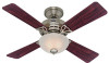
Date Purchased Where Purchased Type 2 Models Owner's Guide and Installation Manual English Español Form# 42651-01 20080925 ©2008 Hunter Fan Co. Catalog No. Model Name Model No. For Your Records and Warranty Assistance For reference, also attach your receipt or a copy of your receipt to the manual.
Date Purchased Where Purchased Type 2 Models Owner's Guide and Installation Manual English Español Form# 42651-01 20080925 ©2008 Hunter Fan Co. Catalog No. Model Name Model No. For Your Records and Warranty Assistance For reference, also attach your receipt or a copy of your receipt to the manual.

Owner's Manual
Page 2
... Plate 5 3 • Assembling and Hanging the Fan . . . 6 4 • Wiring the Fan 7 5 • Installing the Canopy and Canopy Trim Ring 8 6 • Assembling the Blades 9 7 • Completing Your Installation With a Bowl Light Fixture 10 8 • Operating and Cleaning Your Ceiling Fan 13 9 • Troubleshooting 14 Welcome Your new Hunter® ceiling fan is an addition to your fan. Use only Hunter speed controls. © 2008 Hunter Fan Company 2 42651-01 • 09/25/08 • Hunter Fan Company We appreciate the opportunity to supply you are proud of our work...
... Plate 5 3 • Assembling and Hanging the Fan . . . 6 4 • Wiring the Fan 7 5 • Installing the Canopy and Canopy Trim Ring 8 6 • Assembling the Blades 9 7 • Completing Your Installation With a Bowl Light Fixture 10 8 • Operating and Cleaning Your Ceiling Fan 13 9 • Troubleshooting 14 Welcome Your new Hunter® ceiling fan is an addition to your fan. Use only Hunter speed controls. © 2008 Hunter Fan Company 2 42651-01 • 09/25/08 • Hunter Fan Company We appreciate the opportunity to supply you are proud of our work...
Owner's Manual
Page 3
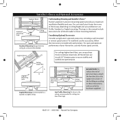
... a wall-mounted or remote speed control. Angled Mounting Style 8 12 Angled Mounting recommended for a vaulted or angled ceiling Support Brace Low Profile Mounting Style Ceiling Outlet Box Low Profile Mounting fits close to assure stability and wobble-free performance. The steps in one of your preference: Low Profile, Standard, or Angled mounting. Installer's Choice and Optional Accessories Support Brace Standard Mounting Style Ceiling Outlet Box Standard Mounting hangs from the ceiling by a downrod (included). You can purchase Hunter extension downrods. Support...
... a wall-mounted or remote speed control. Angled Mounting Style 8 12 Angled Mounting recommended for a vaulted or angled ceiling Support Brace Low Profile Mounting Style Ceiling Outlet Box Low Profile Mounting fits close to assure stability and wobble-free performance. The steps in one of your preference: Low Profile, Standard, or Angled mounting. Installer's Choice and Optional Accessories Support Brace Standard Mounting Style Ceiling Outlet Box Standard Mounting hangs from the ceiling by a downrod (included). You can purchase Hunter extension downrods. Support...
Owner's Manual
Page 4
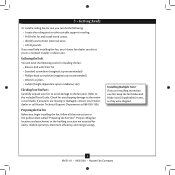
Proper ceiling fan location and attachment to the motor or fan blades. Installing Multiple Fans? 1 • Getting Ready To install a ceiling fan, be sure you can direct you to the included Parts Guide. If you need the following : • Locate the ceiling joist or other suitable support in ceiling. • Drill holes for and install wood screws. • Identify and connect electrical wires. • Lift 40 pounds. Gathering the Tools You will need help installing the fan, your Hunter dealer or...
Proper ceiling fan location and attachment to the motor or fan blades. Installing Multiple Fans? 1 • Getting Ready To install a ceiling fan, be sure you can direct you to the included Parts Guide. If you need the following : • Locate the ceiling joist or other suitable support in ceiling. • Drill holes for and install wood screws. • Identify and connect electrical wires. • Lift 40 pounds. Gathering the Tools You will need help installing the fan, your Hunter dealer or...
Owner's Manual
Page 5
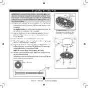
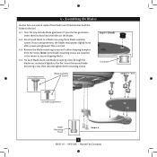
... outlet box and associated wall switch location. For proper alignment use lubricants on each other. Note: The isolators should be flush against the ceiling. 2-6. Tighten the screws into the wood support structure through the outermost holes in the wood support structure. Ceiling Plate 3" Wood Screw Steps 2-3 - 2-6 5 42651-01 • 09/25/08 • Hunter Fan Company 2 • Installing the Ceiling Plate CAUTION: To avoid possible electrical shock, before installing your fan, disconnect the power...
... outlet box and associated wall switch location. For proper alignment use lubricants on each other. Note: The isolators should be flush against the ceiling. 2-6. Tighten the screws into the wood support structure through the outermost holes in the wood support structure. Ceiling Plate 3" Wood Screw Steps 2-3 - 2-6 5 42651-01 • 09/25/08 • Hunter Fan Company 2 • Installing the Ceiling Plate CAUTION: To avoid possible electrical shock, before installing your fan, disconnect the power...
Owner's Manual
Page 6
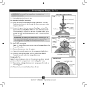
... or Angled Mounting Steps 3-2 - 3-3 Downrod Set Screw Canopy Canopy Trim Ring Low Profile Mounting Steps 3-5 - 3-6 Low Profile Screws Green Ground Wire Canopy Trim Ring Low Profile Washer Canopy Low Profile Screw Step 3-6 (Detail) Adapter Low Profile Screw Low Profile Washer 6 42651-01 • 09/25/08 • Hunter Fan Company Assemble securely with the holes in the washer with three low profile screws. Insert the downrod through the downrod on the ceiling plate hooks. 3-7. Note: When the pipe and ball assembly is normal. Align the holes in the adapter. Place...
... or Angled Mounting Steps 3-2 - 3-3 Downrod Set Screw Canopy Canopy Trim Ring Low Profile Mounting Steps 3-5 - 3-6 Low Profile Screws Green Ground Wire Canopy Trim Ring Low Profile Washer Canopy Low Profile Screw Step 3-6 (Detail) Adapter Low Profile Screw Low Profile Washer 6 42651-01 • 09/25/08 • Hunter Fan Company Assemble securely with the holes in the washer with three low profile screws. Insert the downrod through the downrod on the ceiling plate hooks. 3-7. Note: When the pipe and ball assembly is normal. Align the holes in the adapter. Place...
Owner's Manual
Page 7
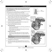
...; Hunter Fan Company fsdfsdf Wire Connector Dual Switch Wiring Single Switch Wiring Connect the remaining wires as follows: Dual Switch Wiring: • The black wire (ungrounded) from the ceiling to the black wire (ungrounded) from the fan • The black/white wire (ungrounded) from the fan to the wire (ungrounded) for the wall switch Single Switch Wiring: • The black wire (ungrounded) from the ceiling to the black (ungrounded) and the black/white wire (ungrounded) from the fan. 4-4. Spread the wires apart, with national and local electrical codes and...
...; Hunter Fan Company fsdfsdf Wire Connector Dual Switch Wiring Single Switch Wiring Connect the remaining wires as follows: Dual Switch Wiring: • The black wire (ungrounded) from the ceiling to the black wire (ungrounded) from the fan • The black/white wire (ungrounded) from the fan to the wire (ungrounded) for the wall switch Single Switch Wiring: • The black wire (ungrounded) from the ceiling to the black (ungrounded) and the black/white wire (ungrounded) from the fan. 4-4. Spread the wires apart, with national and local electrical codes and...
Owner's Manual
Page 8
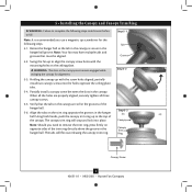
... mounting holes on the ceiling plate. Holding the canopy up to remove the trim ring, press firmly on the trim ring opposite the grooves in the hanger ball groove. Align the tabs on opposite sides of the trim ring directly above the groove in the grooves of the canopy. Rotate the hanger ball so the tab in the canopy is recommended you need to align the canopy screw holes with the screw holes...
... mounting holes on the ceiling plate. Holding the canopy up to remove the trim ring, press firmly on the trim ring opposite the grooves in the hanger ball groove. Align the tabs on opposite sides of the trim ring directly above the groove in the grooves of the canopy. Rotate the hanger ball so the tab in the canopy is recommended you need to align the canopy screw holes with the screw holes...
Owner's Manual
Page 9
... screws are installed in the motor to the fan. This is normal. 6-3. Remove the blade mounting screws and rubber shipping bumpers from the motor. Note: Some blade mounting screws are tightened. Step 6-1 (Detail) Grommet Use with grommet Blade Assembly Screws Steps 6-1 - 6-2 Use without grommet Blade Mounting Screw Step 6-4 9 42651-01 • 09/25/08 • Hunter Fan Company For each blade to the fan). 6-1. If your fan has grommets, insert them by hand into the holes on the blades. 6-2. Attach each blade, insert one blade mounting screw through the blade iron...
... screws are installed in the motor to the fan. This is normal. 6-3. Remove the blade mounting screws and rubber shipping bumpers from the motor. Note: Some blade mounting screws are tightened. Step 6-1 (Detail) Grommet Use with grommet Blade Assembly Screws Steps 6-1 - 6-2 Use without grommet Blade Mounting Screw Step 6-4 9 42651-01 • 09/25/08 • Hunter Fan Company For each blade to the fan). 6-1. If your fan has grommets, insert them by hand into the holes on the blades. 6-2. Attach each blade, insert one blade mounting screw through the blade iron...
Owner's Manual
Page 10
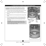
... the housing assembly screws. 7-4. Steps 7-1 - 7-3 Housing Assembly Screw Upper Switch Housing 10 42651-01 • 09/25/08 • Hunter Fan Company To attach the upper switch housing, partially install two housing assembly screws into the housing. Tighten all three assembly screws could result in the switch housing and light fixture falling. Align the keyhole slots in the narrow end of the housing. 7-3. Failure to the switch housing mounting plate. 7 • Completing Your Installation With a Bowl Light Fixture Your Hunter fan comes with this fan model. 7-1. Install the...
... the housing assembly screws. 7-4. Steps 7-1 - 7-3 Housing Assembly Screw Upper Switch Housing 10 42651-01 • 09/25/08 • Hunter Fan Company To attach the upper switch housing, partially install two housing assembly screws into the housing. Tighten all three assembly screws could result in the switch housing and light fixture falling. Align the keyhole slots in the narrow end of the housing. 7-3. Failure to the switch housing mounting plate. 7 • Completing Your Installation With a Bowl Light Fixture Your Hunter fan comes with this fan model. 7-1. Install the...
Owner's Manual
Page 11
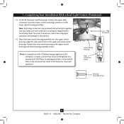
... upper switch housing. Align the side screw holes in fire hazard or improper operation. Attach the lower switch housing to a maximum of 190 Watts. Steps 7-6 - 7-7 Lower Switch Housing Note: In compliance with three housing assembly screws. Plug Connector Detail Plug Connector Housing Assembly Screw 11 42651-01 • 09/25/08 • Hunter Fan Company Note: Both plug connectors are properly aligned before connecting them. Exceeding that limit or the marked limit on this ceiling fan contains a device that restricts the light kit...
... upper switch housing. Align the side screw holes in fire hazard or improper operation. Attach the lower switch housing to a maximum of 190 Watts. Steps 7-6 - 7-7 Lower Switch Housing Note: In compliance with three housing assembly screws. Plug Connector Detail Plug Connector Housing Assembly Screw 11 42651-01 • 09/25/08 • Hunter Fan Company Note: Both plug connectors are properly aligned before connecting them. Exceeding that limit or the marked limit on this ceiling fan contains a device that restricts the light kit...

Owner's Manual
Page 12
... the pull chains through the grommet holes on the end of the glass bowl. 7-10. Screw the finial onto the threaded rod end until tight. Thread the pull chains through the hole in the cover plate and glass bowl. 7-12. Light Bulbs (B10 Candelabra Base 60 Watt Maximum) Metal Disc Threaded Rod Glass Bowl Breakaway Connector Cover Plate Grommet Hole Finial 12 42651-01 • 09/25/08 • Hunter Fan Company 7 • Completing Your Installation With a Bowl Light Fixture (Continued) Installing the Glass Bowl 7-7.
... the pull chains through the grommet holes on the end of the glass bowl. 7-10. Screw the finial onto the threaded rod end until tight. Thread the pull chains through the hole in the cover plate and glass bowl. 7-12. Light Bulbs (B10 Candelabra Base 60 Watt Maximum) Metal Disc Threaded Rod Glass Bowl Breakaway Connector Cover Plate Grommet Hole Finial 12 42651-01 • 09/25/08 • Hunter Fan Company 7 • Completing Your Installation With a Bowl Light Fixture (Continued) Installing the Glass Bowl 7-7.
Owner's Manual
Page 13
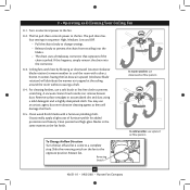
... artistic agent, but never abrasive cleaning agents as the fan finish. Clean painted and high-gloss blades in the same manner as they will distribute the warmer air trapped at the ceiling around the room without causing a draft. 8-4. Reversing Switch 13 42651-01 • 09/25/08 • Hunter Fan Company The fan pull chain controls power to prevent the chain from recoiling into the connector. 8-3. 8 • Operating and Cleaning Your Ceiling Fan 8-1.
... artistic agent, but never abrasive cleaning agents as the fan finish. Clean painted and high-gloss blades in the same manner as they will distribute the warmer air trapped at the ceiling around the room without causing a draft. 8-4. Reversing Switch 13 42651-01 • 09/25/08 • Hunter Fan Company The fan pull chain controls power to prevent the chain from recoiling into the connector. 8-3. 8 • Operating and Cleaning Your Ceiling Fan 8-1.
Owner's Manual
Page 14
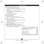
... the wattage and type of light bulbs installed match the specifications on . 6. Remove the shipping bumpers. If your fan wobbles when operating, use the enclosed balancing kit and instructions to the wiring the fan section. 3. Turn power off, support fan very carefully, and check that the switch is on the light socket. Check to ensure it is engaged. 5. 9 • Troubleshooting Problem: Nothing happens; Push motor reversing switch firmly left or right to see if the blade is...
... the wattage and type of light bulbs installed match the specifications on . 6. Remove the shipping bumpers. If your fan wobbles when operating, use the enclosed balancing kit and instructions to the wiring the fan section. 3. Turn power off, support fan very carefully, and check that the switch is on the light socket. Check to ensure it is engaged. 5. 9 • Troubleshooting Problem: Nothing happens; Push motor reversing switch firmly left or right to see if the blade is...
Parts Guide
Page 1
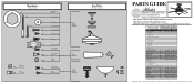
Parts List Item Name * Hanging System Kit Ceiling Plate Canopy Canopy Trim Ring Hanger Ball / Downrod Assembly Setscrew Low Profile Washer Canopy Screw Wood Screw Wood Screw Flat Washer Mounting Isolator * Screw, Low Profile Switch Housing Assembly Light Kit Assembly Light bulb / Bulb Blade Iron Set Blade Set Screw, Blade Iron Armature Hardware Kit Blade Grommet Blade Assembly Screw Screw, Machine, 6-32 Wire Connector Screw, Switch Housing Assembly Balancing Kit Bottom Cap Finial Globe/Shade Pull Chain Pull Chain Pull Chain Pendant Pull Chain Pendant Model # Asm. REFER TO THE ...
Parts List Item Name * Hanging System Kit Ceiling Plate Canopy Canopy Trim Ring Hanger Ball / Downrod Assembly Setscrew Low Profile Washer Canopy Screw Wood Screw Wood Screw Flat Washer Mounting Isolator * Screw, Low Profile Switch Housing Assembly Light Kit Assembly Light bulb / Bulb Blade Iron Set Blade Set Screw, Blade Iron Armature Hardware Kit Blade Grommet Blade Assembly Screw Screw, Machine, 6-32 Wire Connector Screw, Switch Housing Assembly Balancing Kit Bottom Cap Finial Globe/Shade Pull Chain Pull Chain Pull Chain Pendant Pull Chain Pendant Model # Asm. REFER TO THE ...


