
Installation Guide
Page 1
.... For instructions to install your ceiling fan, go to your new Hunter fan. If you to outlet box by wood screws and washers through the drywall or plaster of the fan blade tips. • e fan is positioned to allow you cannot lock...57443;e fan blades have now successfully prepared your fan manual and continue with the rotating fan blades during normal operation. • e fan blades are turned off every item, prepare a new fan site as follows: 3-1. Fan Support System Fan Support System Suitable Existing Fan Site Wiring Outlet Box Hunter Fan Company Step...
.... For instructions to install your ceiling fan, go to your new Hunter fan. If you to outlet box by wood screws and washers through the drywall or plaster of the fan blade tips. • e fan is positioned to allow you cannot lock...57443;e fan blades have now successfully prepared your fan manual and continue with the rotating fan blades during normal operation. • e fan blades are turned off every item, prepare a new fan site as follows: 3-1. Fan Support System Fan Support System Suitable Existing Fan Site Wiring Outlet Box Hunter Fan Company Step...

Owner's Manual
Page 1
Model Name Model No. Date Purchased Where Purchased Type T,G,B Models Owner's Guide and Installation Manual English Español Form# 41847-01 20100528 ©2010 Hunter Fan Co. For Your Records and Warranty Assistance For reference, also attach your receipt or a copy of your receipt to the manual.
Model Name Model No. Date Purchased Where Purchased Type T,G,B Models Owner's Guide and Installation Manual English Español Form# 41847-01 20100528 ©2010 Hunter Fan Co. For Your Records and Warranty Assistance For reference, also attach your receipt or a copy of your receipt to the manual.
Owner's Manual
Page 2
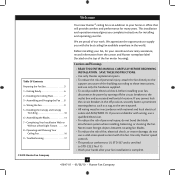
... not use a qualified electrician. • To reduce the risk of the fan motor housing). This installation and operation manual gives you with this fan. Welcome Your new Hunter® ceiling fan is complete. © 2010 Hunter Fan Company 2 41847-01 • 05/28/10 • Hunter Fan Company We are unfamiliar with wiring, use a solid-state speed control...
... not use a qualified electrician. • To reduce the risk of the fan motor housing). This installation and operation manual gives you with this fan. Welcome Your new Hunter® ceiling fan is complete. © 2010 Hunter Fan Company 2 41847-01 • 05/28/10 • Hunter Fan Company We are unfamiliar with wiring, use a solid-state speed control...

Owner's Manual
Page 3
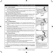
...approved connector. • Six inches of the fan blade tips. • e fan is directly below the joist or support brace. Preparing the Fan Site Step 1 - If your new Hunter fan. Choose the Fan Site Proper ceiling fan location and attachment to the joist or support..., maximum efficiency, and energy savings. Fan Support System Fan Support System Suitable Existing Fan Site Wiring Outlet Box 3 41847-01 • 05/28/10 • Hunter Fan Company Fan Support System • Fan attaches directly to building structure. • Fan support system will hold the outlet box...
...approved connector. • Six inches of the fan blade tips. • e fan is directly below the joist or support brace. Preparing the Fan Site Step 1 - If your new Hunter fan. Choose the Fan Site Proper ceiling fan location and attachment to the joist or support..., maximum efficiency, and energy savings. Fan Support System Fan Support System Suitable Existing Fan Site Wiring Outlet Box 3 41847-01 • 05/28/10 • Hunter Fan Company Fan Support System • Fan attaches directly to building structure. • Fan support system will hold the outlet box...
Owner's Manual
Page 4
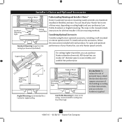
... use a qualified electrician. 4 41847-01 • 05/28/10 • Hunter Fan Company If the joist is there, determine if it is a ceiling joist directly above the ceiling hole. Position it will hold the outlet box and fan. 2-2. Drill pilot holes no larger than the minor diameter of the wood screws ...allow you to the support brace or joist with an approved connector, available at least 6" beyond the box. 5-3. Attach the fan supply line to your ceiling fan site. Locate the site for the ceiling hole directly below the joist or support brace that both the inner and outer holes ...
... use a qualified electrician. 4 41847-01 • 05/28/10 • Hunter Fan Company If the joist is there, determine if it is a ceiling joist directly above the ceiling hole. Position it will hold the outlet box and fan. 2-2. Drill pilot holes no larger than the minor diameter of the wood screws ...allow you to the support brace or joist with an approved connector, available at least 6" beyond the box. 5-3. Attach the fan supply line to your ceiling fan site. Locate the site for the ceiling hole directly below the joist or support brace that both the inner and outer holes ...
Owner's Manual
Page 5
... wobble-free performance. The steps in one of three ways, depending on ceiling height and your Hunter fan, use only the hardware supplied. 5 41847-01 • 05/28/10 • Hunter Fan Company Support Brace Ceiling Outlet Box For ceilings higher than 8 feet high CAUTION: To reduce the... risk of personal injury, attach the fan directly to these instructions, and use only Hunter speed controls. For quiet and optimum performance of the building according to the support structure of your preference: Low ...
... wobble-free performance. The steps in one of three ways, depending on ceiling height and your Hunter fan, use only the hardware supplied. 5 41847-01 • 05/28/10 • Hunter Fan Company Support Brace Ceiling Outlet Box For ceilings higher than 8 feet high CAUTION: To reduce the... risk of personal injury, attach the fan directly to these instructions, and use only Hunter speed controls. For quiet and optimum performance of the building according to the support structure of your preference: Low ...
Owner's Manual
Page 6
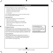
... If you are missing or damaged, contact your Hunter dealer or call Hunter Technical Support Department at 888-830-1326. Installing Multiple Fans? If any shipping damage to the motor or fan blades. Proper ceiling fan location and attachment to the building structure are essential...-head screwdriver (magnetic tip recommended) • Wrench or pliers • Ladder (height dependent upon installation site) Checking Your Fan Parts Carefully unpack your Hunter fan dealer can do the following tools for and install wood screws. • Identify and connect electrical wires. • Lift ...
... If you are missing or damaged, contact your Hunter dealer or call Hunter Technical Support Department at 888-830-1326. Installing Multiple Fans? If any shipping damage to the motor or fan blades. Proper ceiling fan location and attachment to the building structure are essential...-head screwdriver (magnetic tip recommended) • Wrench or pliers • Ladder (height dependent upon installation site) Checking Your Fan Parts Carefully unpack your Hunter fan dealer can do the following tools for and install wood screws. • Identify and connect electrical wires. • Lift ...
Owner's Manual
Page 7
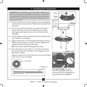
..."). For proper alignment use lubricants on the screws. 2 • Installing the Ceiling Plate CAUTION: To avoid possible electrical shock, before installing your fan, disconnect the power by inserting the raised areas on each isolator into the holes in the ceiling plate. 2-3. Drill two pilot holes into the ... plate. 2-4. Place a flat washer on the ceiling plate are pointing toward the ceiling peak. 7 41847-01 • 05/28/10 • Hunter Fan Company do not use slotted holes directly across from the outlet box down through the hole in the middle of the two 3" wood screws and...
..."). For proper alignment use lubricants on the screws. 2 • Installing the Ceiling Plate CAUTION: To avoid possible electrical shock, before installing your fan, disconnect the power by inserting the raised areas on each isolator into the holes in the ceiling plate. 2-3. Drill two pilot holes into the ... plate. 2-4. Place a flat washer on the ceiling plate are pointing toward the ceiling peak. 7 41847-01 • 05/28/10 • Hunter Fan Company do not use slotted holes directly across from the outlet box down through the hole in the middle of the two 3" wood screws and...
Owner's Manual
Page 8
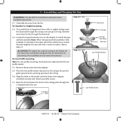
... - 3-3 Downrod Canopy Canopy Trim Ring Setscrew Steps 3-5 - 3-6 Low Profile Washer Low Profile Screw 8 41847-01 • 05/28/10 • Hunter Fan Company Do not remove this is fully installed, 2-3 threads on the adapter to Step 3-7. CAUTION: The adapter has a special coating on the ceiling plate through... the canopy and canopy trim ring. the coating prevents the downrod from the fan through the downrod. 3-3. Skip to install the pipe and ball assembly. For Low Profile mounting: Note: For low profile mounting, ...
... - 3-3 Downrod Canopy Canopy Trim Ring Setscrew Steps 3-5 - 3-6 Low Profile Washer Low Profile Screw 8 41847-01 • 05/28/10 • Hunter Fan Company Do not remove this is fully installed, 2-3 threads on the adapter to Step 3-7. CAUTION: The adapter has a special coating on the ceiling plate through... the canopy and canopy trim ring. the coating prevents the downrod from the fan through the downrod. 3-3. Skip to install the pipe and ball assembly. For Low Profile mounting: Note: For low profile mounting, ...
Owner's Manual
Page 9
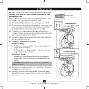
... • The black wire (ungrounded) from the ceiling to the white wire (grounded) from the fan. 4-4. Wire Connector Dual Switch Wiring Single Switch Wiring 9 41847-01 • 05/28/10 • Hunter Fan Company Connect the bare or green ground wire (grounding) from the ceiling to the green ground wire ...(grounding) from the ceiling plate and the green ground wire from the fan. 4-5. Spread the wires apart, with wiring, use the wire...
... • The black wire (ungrounded) from the ceiling to the white wire (grounded) from the fan. 4-4. Wire Connector Dual Switch Wiring Single Switch Wiring 9 41847-01 • 05/28/10 • Hunter Fan Company Connect the bare or green ground wire (grounding) from the ceiling to the green ground wire ...(grounding) from the ceiling plate and the green ground wire from the fan. 4-5. Spread the wires apart, with wiring, use the wire...
Owner's Manual
Page 10
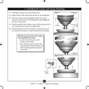
Raise the canopy over the ceiling plate. Rotate the canopy clockwise until the tabs on top of tabs. 2. Holding the canopy, raise the fan off the hook. 5-2. Step 5-2 Canopy Should you need to the top of the ring toward the canopy. Locate the tab indicators, small bumps ... with the slots in the canopy. 5-4. Steps 5-4 - 5-5 Ceiling Plate Canopy Trim Ring Step 5-3 Canopy Screw 10 41847-01 • 05/28/10 • Hunter Fan Company 5 • Installing the Canopy and Canopy Trim Ring 5-1. Using both hands, push the canopy trim ring up to remove the canopy trim ring, follow...
Raise the canopy over the ceiling plate. Rotate the canopy clockwise until the tabs on top of tabs. 2. Holding the canopy, raise the fan off the hook. 5-2. Step 5-2 Canopy Should you need to the top of the ring toward the canopy. Locate the tab indicators, small bumps ... with the slots in the canopy. 5-4. Steps 5-4 - 5-5 Ceiling Plate Canopy Trim Ring Step 5-3 Canopy Screw 10 41847-01 • 05/28/10 • Hunter Fan Company 5 • Installing the Canopy and Canopy Trim Ring 5-1. Using both hands, push the canopy trim ring up to remove the canopy trim ring, follow...
Owner's Manual
Page 11
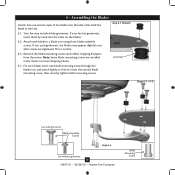
... securely tighten both mounting screws. For each blade to the fan. Step 6-1 (Detail) Grommet Steps 6-1 - 6-2 Use with grommet Blade Assembly Screws Step 6-4 Use without grommet 11 41847-01 • 05/28/10 • Hunter Fan Company Blade Mounting Screw Attach each blade, insert one blade ...mounting screw through the blade iron, and attach lightly to a blade iron using three blade assembly screws. Your fan may appear slightly loose after screws are installed ...
... securely tighten both mounting screws. For each blade to the fan. Step 6-1 (Detail) Grommet Steps 6-1 - 6-2 Use with grommet Blade Assembly Screws Step 6-4 Use without grommet 11 41847-01 • 05/28/10 • Hunter Fan Company Blade Mounting Screw Attach each blade, insert one blade ...mounting screw through the blade iron, and attach lightly to a blade iron using three blade assembly screws. Your fan may appear slightly loose after screws are installed ...

Owner's Manual
Page 12
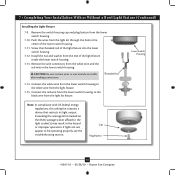
...7-3 Housing Assembly Screw Upper Switch Housing 12 41847-01 • 05/28/10 • Hunter Fan Company 7 • Completing Your Installation With or Without a Bowl Light Fixture Your Hunter fan comes with this fan model. 7-1. If you want to "Installing the Light Fixture" on page 12. Install the ... and an optional switch housing cap and plug button. Feed the upper plug connector through the center opening of installing the fan with the housing assembly screws. 7-4. Align the keyhole slots in the switch housing and light fixture falling. 7-5. Tighten all...
...7-3 Housing Assembly Screw Upper Switch Housing 12 41847-01 • 05/28/10 • Hunter Fan Company 7 • Completing Your Installation With or Without a Bowl Light Fixture Your Hunter fan comes with this fan model. 7-1. If you want to "Installing the Light Fixture" on page 12. Install the ... and an optional switch housing cap and plug button. Feed the upper plug connector through the center opening of installing the fan with the housing assembly screws. 7-4. Align the keyhole slots in the switch housing and light fixture falling. 7-5. Tighten all...

Owner's Manual
Page 13
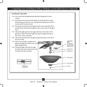
... with three housing assembly screws. Steps 7-6 - 7-7 Lower Switch Housing Plug Connector Detail Plug Connector Housing Assembly Screw 13 41847-01 • 05/28/10 • Hunter Fan Company Align the side screw holes in the lower switch housing assembly. 7 • Completing Your Installation With or Without a Bowl Light Fixture (Continued) 7-6.
... with three housing assembly screws. Steps 7-6 - 7-7 Lower Switch Housing Plug Connector Detail Plug Connector Housing Assembly Screw 13 41847-01 • 05/28/10 • Hunter Fan Company Align the side screw holes in the lower switch housing assembly. 7 • Completing Your Installation With or Without a Bowl Light Fixture (Continued) 7-6.
Owner's Manual
Page 14
...from the light kit through the hole in the lower switch housing. Lower Switch Housing Note: In compliance with US federal energy regulations, this ceiling fan contains a device that restricts its light output. Remove the wire connectors from the light fixture. 7-15. Steps 7-17 - 7-19 Cap Plug ...Button Step 7-21 14 41847-01 • 05/28/10 • Hunter Fan Company Screw the threaded rod of the light fixture inside the lower switch housing. 7-13. Connect the red wire from the lower switch housing to...
...from the light kit through the hole in the lower switch housing. Lower Switch Housing Note: In compliance with US federal energy regulations, this ceiling fan contains a device that restricts its light output. Remove the wire connectors from the light fixture. 7-15. Steps 7-17 - 7-19 Cap Plug ...Button Step 7-21 14 41847-01 • 05/28/10 • Hunter Fan Company Screw the threaded rod of the light fixture inside the lower switch housing. 7-13. Connect the red wire from the lower switch housing to...
Owner's Manual
Page 15
... Disk Breakaway Connector Glass Bowl Cover Plate Finial 15 41847-01 • 05/28/10 • Hunter Fan Company Then, thread the fan pull chain through the hole in the center of the glass bowl. Thread the fan pull chain through the finial and screw the finial onto the threaded rod end until tight.... 7-21. Thread the light pull chain through the hole in the center of the extra chain.) 7-18. Attach the extra pull chain (included) to the fan pull chain using the breakaway connector. (You may find the breakaway connector on the end of the cover plate. 7-20. Then, Thread the light pull...
... Disk Breakaway Connector Glass Bowl Cover Plate Finial 15 41847-01 • 05/28/10 • Hunter Fan Company Then, thread the fan pull chain through the hole in the center of the glass bowl. Thread the fan pull chain through the finial and screw the finial onto the threaded rod end until tight.... 7-21. Thread the light pull chain through the hole in the center of the extra chain.) 7-18. Attach the extra pull chain (included) to the fan pull chain using the breakaway connector. (You may find the breakaway connector on the end of the cover plate. 7-20. Then, Thread the light pull...
Owner's Manual
Page 16
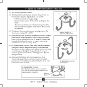
...air trapped at the ceiling around the room without causing a draft. 8-5. Reversing Switch 16 41847-01 • 05/28/10 • Hunter Fan Company Ceiling fans work best by blowing air downward (counterclockwise blade rotation) in sequence: High, Medium, Low, and Off. • Pull the chain slowly... use downward air flow pattern In cold weather, use a soft brush or lint-free cloth to the opposite position. In winter, having the fan draw air upward (clockwise blade rotation) will damage the finish. 8-6. A vacuum cleaner brush nozzle can remove heavier dust. Occasionally, apply a ...
...air trapped at the ceiling around the room without causing a draft. 8-5. Reversing Switch 16 41847-01 • 05/28/10 • Hunter Fan Company Ceiling fans work best by blowing air downward (counterclockwise blade rotation) in sequence: High, Medium, Low, and Off. • Pull the chain slowly... use downward air flow pattern In cold weather, use a soft brush or lint-free cloth to the opposite position. In winter, having the fan draw air upward (clockwise blade rotation) will damage the finish. 8-6. A vacuum cleaner brush nozzle can remove heavier dust. Occasionally, apply a ...
Owner's Manual
Page 17
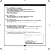
...ensure that the switch is still operating 1. Hunter Fan Company 7130 Goodlett Farms Parkway #400 Memphis, Tennessee 38016 17 41847-01 • 05/28/10 • Hunter Fan Company Problem: Noisy operation. 1. Problem: Lights shut off suddenly, but fan is engaged. 5. Replace the CFL bulbs ...with dimmable light bulbs, or install the fan in the switch housing. 4. Loosen canopy, check all the ...
...ensure that the switch is still operating 1. Hunter Fan Company 7130 Goodlett Farms Parkway #400 Memphis, Tennessee 38016 17 41847-01 • 05/28/10 • Hunter Fan Company Problem: Noisy operation. 1. Problem: Lights shut off suddenly, but fan is engaged. 5. Replace the CFL bulbs ...with dimmable light bulbs, or install the fan in the switch housing. 4. Loosen canopy, check all the ...
Parts Guide
Page 1
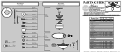
If parts are included in the box. THIS PARTS GUIDE IS FOR REFERENCE ONLY. Dwg. # Finish Qnty 1 23763 94325-01 Weathered Bronze Part # 94945-01 21648 94325-02 White Part # 94945-01 1 G0662-27 G0662-27 1 92792-05 92792-05 1 74853-01 74853-01 11 63755-05 63755-05 1 94322-00-...-01 1 63756-06 63756-06 1 08198-01 08198-01 1 08200-01 08200-01 1 73853-01 73853-01 1 73854-01 73854-01 1 97177-01 97177-01 Hunter Fan Company • 2500 Frisco Avenue • Memphis, TN 38114 • www.hunterfan.com • 98000-01-272 08-18-2011 • ©2011 REFER TO...
If parts are included in the box. THIS PARTS GUIDE IS FOR REFERENCE ONLY. Dwg. # Finish Qnty 1 23763 94325-01 Weathered Bronze Part # 94945-01 21648 94325-02 White Part # 94945-01 1 G0662-27 G0662-27 1 92792-05 92792-05 1 74853-01 74853-01 11 63755-05 63755-05 1 94322-00-...-01 1 63756-06 63756-06 1 08198-01 08198-01 1 08200-01 08200-01 1 73853-01 73853-01 1 73854-01 73854-01 1 97177-01 97177-01 Hunter Fan Company • 2500 Frisco Avenue • Memphis, TN 38114 • www.hunterfan.com • 98000-01-272 08-18-2011 • ©2011 REFER TO...


