
Installation Guide
Page 1
... electrical supply house. 5-4. If your existing fan site is directly below a joist or support brace that the fan supply line extends at any hardware store or electrical supply house. 4-2. Make sure the circuit breakers to the fan supply line leads and associated wall switch location are unfamiliar with wiring, use the hole to your ceiling fan site. For instructions to install your ceiling fan, go to install the support brace and outlet box. Choose a fan...
... electrical supply house. 5-4. If your existing fan site is directly below a joist or support brace that the fan supply line extends at any hardware store or electrical supply house. 4-2. Make sure the circuit breakers to the fan supply line leads and associated wall switch location are unfamiliar with wiring, use the hole to your ceiling fan site. For instructions to install your ceiling fan, go to install the support brace and outlet box. Choose a fan...

Owner's Manual
Page 1
Model Name Model No. Date Purchased Where Purchased Type T,G,B Models Owner's Guide and Installation Manual English Español Form# 41847-01 20100528 ©2010 Hunter Fan Co. For Your Records and Warranty Assistance For reference, also attach your receipt or a copy of your receipt to the manual.
Model Name Model No. Date Purchased Where Purchased Type T,G,B Models Owner's Guide and Installation Manual English Español Form# 41847-01 20100528 ©2010 Hunter Fan Co. For Your Records and Warranty Assistance For reference, also attach your receipt or a copy of your receipt to the manual.
Owner's Manual
Page 2
... 3 1 • Getting Ready 6 2 • Installing the Ceiling Plate 7 3 • Assembling and Hanging the Fan . . . . 8 4 • Wiring the Fan 9 5 • Installing the Canopy and Canopy Trim Ring 10 6 • Assembling the Blades 11 7 • Completing Your Installation With or Without a Bowl Light Fixture 12 8 • Operating and Cleaning Your Ceiling Fan 16 9 • Troubleshooting 17 Cautions and Warnings • READ THIS ENTIRE MANUAL CAREFULLY BEFORE BEGINNING INSTALLATION. Never insert foreign objects between rotating fan blades. • To reduce the...
... 3 1 • Getting Ready 6 2 • Installing the Ceiling Plate 7 3 • Assembling and Hanging the Fan . . . . 8 4 • Wiring the Fan 9 5 • Installing the Canopy and Canopy Trim Ring 10 6 • Assembling the Blades 11 7 • Completing Your Installation With or Without a Bowl Light Fixture 12 8 • Operating and Cleaning Your Ceiling Fan 16 9 • Troubleshooting 17 Cautions and Warnings • READ THIS ENTIRE MANUAL CAREFULLY BEFORE BEGINNING INSTALLATION. Never insert foreign objects between rotating fan blades. • To reduce the...

Owner's Manual
Page 3
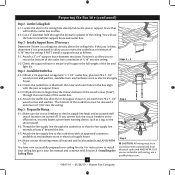
... specified by an approved connector. • Six inches of the fan. 30" From Wall or Nearest Obstruction 7' Minimum Blades to Floor 8' Minimum Ceiling Height Checklist for your existing fan site is recessed a minimum of the fan blade tips. • e fan is directly below the joist or support brace. If your new Hunter fan. Ceiling Hole • e outlet box clearance hole is directly below a joist or support brace that will hold...
... specified by an approved connector. • Six inches of the fan. 30" From Wall or Nearest Obstruction 7' Minimum Blades to Floor 8' Minimum Ceiling Height Checklist for your existing fan site is recessed a minimum of the fan blade tips. • e fan is directly below the joist or support brace. If your new Hunter fan. Ceiling Hole • e outlet box clearance hole is directly below a joist or support brace that will hold...
Owner's Manual
Page 4
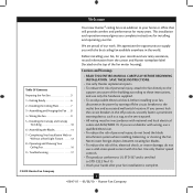
... 4 wood screws and washers. e bottom of the outlet box must be recessed a minimum of 1/16" into the ceiling. Attach a 2" x 4" support brace between two joists. Cut a 4" diameter hole through the inner holes of the fan and light kit. Attach the fan supply line to install the support brace and outlet box. Step 5 CAUTION: All wiring must be in accordance with national and local electrical codes and ANSI...
... 4 wood screws and washers. e bottom of the outlet box must be recessed a minimum of 1/16" into the ceiling. Attach a 2" x 4" support brace between two joists. Cut a 4" diameter hole through the inner holes of the fan and light kit. Attach the fan supply line to install the support brace and outlet box. Step 5 CAUTION: All wiring must be in accordance with national and local electrical codes and ANSI...
Owner's Manual
Page 5
... optimum performance of three ways, depending on ceiling height and your preference: Low Profile, Standard, or Angled mounting. All Hunter fans use sturdy 3/4" diameter pipe to these instructions, and use only the hardware supplied. 5 41847-01 • 05/28/10 • Hunter Fan Company To install and use only Hunter speed controls. You can purchase Hunter extension downrods. Support Brace Ceiling Outlet Box For ceilings higher than 8 feet high CAUTION: To reduce the risk of personal...
... optimum performance of three ways, depending on ceiling height and your preference: Low Profile, Standard, or Angled mounting. All Hunter fans use sturdy 3/4" diameter pipe to these instructions, and use only the hardware supplied. 5 41847-01 • 05/28/10 • Hunter Fan Company To install and use only Hunter speed controls. You can purchase Hunter extension downrods. Support Brace Ceiling Outlet Box For ceilings higher than 8 feet high CAUTION: To reduce the risk of personal...
Owner's Manual
Page 6
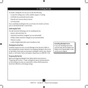
... the fan parts. Preparing the Fan Site Before you can direct you are essential for and install wood screws. • Identify and connect electrical wires. • Lift 40 pounds. Proper ceiling fan location and attachment to the motor or fan blades. Installing Multiple Fans? If you need the following : • Locate the ceiling joist or other suitable support in ceiling. • Drill holes for safety, reliable operation, maximum efficiency, and energy savings. If any shipping...
... the fan parts. Preparing the Fan Site Before you can direct you are essential for and install wood screws. • Identify and connect electrical wires. • Lift 40 pounds. Proper ceiling fan location and attachment to the motor or fan blades. Installing Multiple Fans? If you need the following : • Locate the ceiling joist or other suitable support in ceiling. • Drill holes for safety, reliable operation, maximum efficiency, and energy savings. If any shipping...
Owner's Manual
Page 7
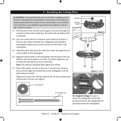
... alignment use lubricants on each of the ceiling plate. 2-4. Place a flat washer on the ceiling plate are pointing toward the ceiling peak. 7 41847-01 • 05/28/10 • Hunter Fan Company 2 • Installing the Ceiling Plate CAUTION: To avoid possible electrical shock, before installing your fan, disconnect the power by inserting the raised areas on the screws. Isolator Ceiling Plate Flat Washer Step 2-2 Steps 2-3 - 2-5 3" Wood Screw For Angled Ceilings: Be sure to the service...
... alignment use lubricants on each of the ceiling plate. 2-4. Place a flat washer on the ceiling plate are pointing toward the ceiling peak. 7 41847-01 • 05/28/10 • Hunter Fan Company 2 • Installing the Ceiling Plate CAUTION: To avoid possible electrical shock, before installing your fan, disconnect the power by inserting the raised areas on the screws. Isolator Ceiling Plate Flat Washer Step 2-2 Steps 2-3 - 2-5 3" Wood Screw For Angled Ceilings: Be sure to the service...
Owner's Manual
Page 8
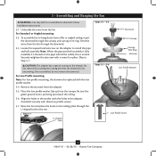
... assembly. 3 • Assembling and Hanging the Fan WARNING: Fan may fall if not assembled as directed in the rim. the coating prevents the downrod from the fan. For Low Profile mounting: Note: For low profile mounting, the downrod is normal. Step 3-7 U-shaped Hole Steps 3-2 - 3-3 Downrod Canopy Canopy Trim Ring Setscrew Steps 3-5 - 3-6 Low Profile Washer Low Profile Screw 8 41847-01 • 05/28/10 • Hunter Fan Company Do not remove this is replaced with the holes in the washer with the low profile washer. 3-4. Align the holes in the adapter...
... assembly. 3 • Assembling and Hanging the Fan WARNING: Fan may fall if not assembled as directed in the rim. the coating prevents the downrod from the fan. For Low Profile mounting: Note: For low profile mounting, the downrod is normal. Step 3-7 U-shaped Hole Steps 3-2 - 3-3 Downrod Canopy Canopy Trim Ring Setscrew Steps 3-5 - 3-6 Low Profile Washer Low Profile Screw 8 41847-01 • 05/28/10 • Hunter Fan Company Do not remove this is replaced with the holes in the washer with the low profile washer. 3-4. Align the holes in the adapter...
Owner's Manual
Page 9
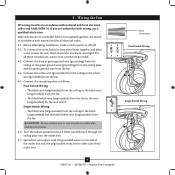
... electrical codes and ANSI/NFPA 70. Before attempting installation, make sure the power is still off. 4-2. Connect the remaining wires as follows: Dual Switch Wiring: • The black wire (ungrounded) from the ceiling to the black wire (ungrounded) from the fan • The black/white wire (ungrounded) from the fan to the wire (ungrounded) for the wall switch Single Switch Wiring: • The black wire (ungrounded) from the ceiling to the white wire (grounded) from the fan. 4-4. Wire Connector Dual Switch Wiring Single Switch Wiring...
... electrical codes and ANSI/NFPA 70. Before attempting installation, make sure the power is still off. 4-2. Connect the remaining wires as follows: Dual Switch Wiring: • The black wire (ungrounded) from the ceiling to the black wire (ungrounded) from the fan • The black/white wire (ungrounded) from the fan to the wire (ungrounded) for the wall switch Single Switch Wiring: • The black wire (ungrounded) from the ceiling to the white wire (grounded) from the fan. 4-4. Wire Connector Dual Switch Wiring Single Switch Wiring...
Owner's Manual
Page 10
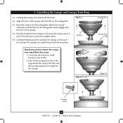
... tabs on top of the ring toward the canopy. Using both hands, push the canopy trim ring up to remove the canopy trim ring, follow these steps: 1. Rotate the canopy clockwise until the tabs on opposite sides of tabs. 2. Partially install the three canopy screws into place. Steps 5-4 - 5-5 Ceiling Plate Canopy Trim Ring Step 5-3 Canopy Screw 10 41847-01 • 05/28/10 • Hunter Fan Company Holding the canopy, raise the fan off the hook. 5-2.
... tabs on top of the ring toward the canopy. Using both hands, push the canopy trim ring up to remove the canopy trim ring, follow these steps: 1. Rotate the canopy clockwise until the tabs on opposite sides of tabs. 2. Partially install the three canopy screws into place. Steps 5-4 - 5-5 Ceiling Plate Canopy Trim Ring Step 5-3 Canopy Screw 10 41847-01 • 05/28/10 • Hunter Fan Company Holding the canopy, raise the fan off the hook. 5-2.
Owner's Manual
Page 11
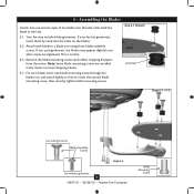
... lightly to a blade iron using three blade assembly screws. For each blade to the fan. This is normal. 6-3. Note: Some blade mounting screws are tightened. Remove the blade mounting screws and rubber shipping bumpers from the motor. Step 6-1 (Detail) Grommet Steps 6-1 - 6-2 Use with grommet Blade Assembly Screws Step 6-4 Use without grommet 11 41847-01 • 05/28/10 • Hunter Fan Company Blade Mounting Screw Insert the second blade mounting screw, then securely tighten both mounting screws. 6 • Assembling the Blades Hunter fans use several styles of fan blade irons...
... lightly to a blade iron using three blade assembly screws. For each blade to the fan. This is normal. 6-3. Note: Some blade mounting screws are tightened. Remove the blade mounting screws and rubber shipping bumpers from the motor. Step 6-1 (Detail) Grommet Steps 6-1 - 6-2 Use with grommet Blade Assembly Screws Step 6-4 Use without grommet 11 41847-01 • 05/28/10 • Hunter Fan Company Blade Mounting Screw Insert the second blade mounting screw, then securely tighten both mounting screws. 6 • Assembling the Blades Hunter fans use several styles of fan blade irons...

Owner's Manual
Page 12
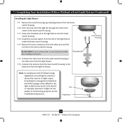
... the switch housing and light fixture falling. 7-5. 7 • Completing Your Installation With or Without a Bowl Light Fixture Your Hunter fan comes with OR without the included light fixture. The steps below direct you whether or not you have installed the light fixture, continue with step 7-6 now. Install the remaining screw into the switch housing mounting plate. 7-2. Steps 7-1 - 7-3 Housing Assembly Screw Upper Switch Housing 12 41847-01 • 05/28/10 • Hunter Fan Company To attach the upper switch housing, partially install two housing assembly screws...
... the switch housing and light fixture falling. 7-5. 7 • Completing Your Installation With or Without a Bowl Light Fixture Your Hunter fan comes with OR without the included light fixture. The steps below direct you whether or not you have installed the light fixture, continue with step 7-6 now. Install the remaining screw into the switch housing mounting plate. 7-2. Steps 7-1 - 7-3 Housing Assembly Screw Upper Switch Housing 12 41847-01 • 05/28/10 • Hunter Fan Company To attach the upper switch housing, partially install two housing assembly screws...

Owner's Manual
Page 13
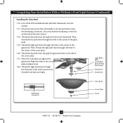
... the lower switch housing, connect the upper plug connector from the motor to install the glass bowl. See "Installing the Glass Bowl" on page 13 for instructions. Otherwise, proceed with three housing assembly screws. Align the side screw holes in the lower switch housing assembly. Steps 7-6 - 7-7 Lower Switch Housing Plug Connector Detail Plug Connector Housing Assembly Screw 13 41847-01 • 05/28/10 • Hunter Fan Company 7 • Completing Your Installation With or Without a Bowl Light Fixture (Continued) 7-6. Place the lower switch housing assembly over...
... the lower switch housing, connect the upper plug connector from the motor to install the glass bowl. See "Installing the Glass Bowl" on page 13 for instructions. Otherwise, proceed with three housing assembly screws. Align the side screw holes in the lower switch housing assembly. Steps 7-6 - 7-7 Lower Switch Housing Plug Connector Detail Plug Connector Housing Assembly Screw 13 41847-01 • 05/28/10 • Hunter Fan Company 7 • Completing Your Installation With or Without a Bowl Light Fixture (Continued) 7-6. Place the lower switch housing assembly over...
Owner's Manual
Page 14
... wire connectors from the light kit fixture. Connect the white wire from the lower switch housing to the black wire from the white wire and the red wire in fire hazard or improper operation. Steps 7-17 - 7-19 Cap Plug Button Step 7-21 14 41847-01 • 05/28/10 • Hunter Fan Company Remove the switch housing cap and plug button from the light kit through the hole in the center of the lower switch housing. 7-11. Screw the threaded rod of the light fixture...
... wire connectors from the light kit fixture. Connect the white wire from the lower switch housing to the black wire from the white wire and the red wire in fire hazard or improper operation. Steps 7-17 - 7-19 Cap Plug Button Step 7-21 14 41847-01 • 05/28/10 • Hunter Fan Company Remove the switch housing cap and plug button from the light kit through the hole in the center of the lower switch housing. 7-11. Screw the threaded rod of the light fixture...
Owner's Manual
Page 15
... pull chain (included) to the fan pull chain using the breakaway connector. (You may find the breakaway connector on the end of the cover plate. 7-21. Light Bulbs (B10 Candelabra Base 60 Watt Maximum) Metal Rod Metal Disk Breakaway Connector Glass Bowl Cover Plate Finial 15 41847-01 • 05/28/10 • Hunter Fan Company Thread the fan pull chain through the hole in the center of the cover plate. 7-20. Then, thread the fan pull chain through the grommet hole...
... pull chain (included) to the fan pull chain using the breakaway connector. (You may find the breakaway connector on the end of the cover plate. 7-21. Light Bulbs (B10 Candelabra Base 60 Watt Maximum) Metal Rod Metal Disk Breakaway Connector Glass Bowl Cover Plate Finial 15 41847-01 • 05/28/10 • Hunter Fan Company Thread the fan pull chain through the hole in the center of the cover plate. 7-20. Then, thread the fan pull chain through the grommet hole...
Owner's Manual
Page 16
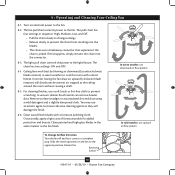
... • Hunter Fan Company The fan pull chain controls power to the fan. 8-2. For cleaning finishes, use an artistic agent, but never abrasive cleaning agents as the fan finish. Clean painted and high-gloss blades in sequence: High, Medium, Low, and Off. • Pull the chain slowly to change settings. • Release slowly to prevent scratching. A vacuum cleaner brush nozzle can remove heavier dust. Slide the reversing switch on electrical power to the fan. Ceiling fans work best by blowing air downward (counterclockwise blade rotation...
... • Hunter Fan Company The fan pull chain controls power to the fan. 8-2. For cleaning finishes, use an artistic agent, but never abrasive cleaning agents as the fan finish. Clean painted and high-gloss blades in sequence: High, Medium, Low, and Off. • Pull the chain slowly to change settings. • Release slowly to prevent scratching. A vacuum cleaner brush nozzle can remove heavier dust. Slide the reversing switch on electrical power to the fan. Ceiling fans work best by blowing air downward (counterclockwise blade rotation...
Owner's Manual
Page 17
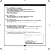
.... 6. Pull the pull chain to make sure the wattage and type of the light bulbs that the switch is cracked. Turn power off at http://www.hunterfan.com. Problem: CFL bulbs flicker when controlled by a dimming remote or wall control 1. 9 • Troubleshooting Problem: Nothing happens; Check the plug connection in a location without a dimming control. Remove the shipping bumpers. Tighten the blade assembly screws and blade iron armature screws until snug. 2. If your fan wobbles when operating, use the enclosed balancing kit and instructions to the light socket. 2. Problem: Lights...
.... 6. Pull the pull chain to make sure the wattage and type of the light bulbs that the switch is cracked. Turn power off at http://www.hunterfan.com. Problem: CFL bulbs flicker when controlled by a dimming remote or wall control 1. 9 • Troubleshooting Problem: Nothing happens; Check the plug connection in a location without a dimming control. Remove the shipping bumpers. Tighten the blade assembly screws and blade iron armature screws until snug. 2. If your fan wobbles when operating, use the enclosed balancing kit and instructions to the light socket. 2. Problem: Lights...
Parts Guide
Page 1
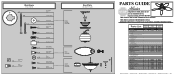
... THE INSTALLATION MANUAL FOR FULL ASSEMBLY INSTRUCTIONS. Parts List Item Name * Hanging System Kit Ceiling Plate Canopy Hanger Ball / Downrod Assembly Setscrew Low Profile Washer Canopy Screw Wood Screw Wood Screw Flat Washer Mounting Isolator * Screw, Low Profile Switch Housing Assembly Blade Iron Set Blade Set Screw, Blade Iron Armature Hardware Kit Blade Grommet Blade Assembly Screw Screw, Machine, 6-32 Wire Connector Screw, Switch Housing Assembly Balancing Kit Pull Chain Pendant Pull Chain Dummy Terminal, Male Dummy Terminal, Female Cap, Switch Housing Plug Button Globe/Shade Model # Asm...
... THE INSTALLATION MANUAL FOR FULL ASSEMBLY INSTRUCTIONS. Parts List Item Name * Hanging System Kit Ceiling Plate Canopy Hanger Ball / Downrod Assembly Setscrew Low Profile Washer Canopy Screw Wood Screw Wood Screw Flat Washer Mounting Isolator * Screw, Low Profile Switch Housing Assembly Blade Iron Set Blade Set Screw, Blade Iron Armature Hardware Kit Blade Grommet Blade Assembly Screw Screw, Machine, 6-32 Wire Connector Screw, Switch Housing Assembly Balancing Kit Pull Chain Pendant Pull Chain Dummy Terminal, Male Dummy Terminal, Female Cap, Switch Housing Plug Button Globe/Shade Model # Asm...


