
Installation Guide
Page 1
... aligned with 2 • Installing the Ceiling Plate. Locate the site for your new Hunter fan. Position it to allow you are unfamiliar with wiring, use an existing fan site, complete the following checklist to determine if the site is an UL-approved octagonal ...8226; No object can come in accordance with the rotating fan blades during normal operation. • e fan blades are at least 7 feet above the ceiling hole. Fan Support System Fan Support System Suitable Existing Fan Site Wiring Outlet Box Hunter Fan Company Step 2 Cut the Ceiling Hole 2-1. Obtain a ...
... aligned with 2 • Installing the Ceiling Plate. Locate the site for your new Hunter fan. Position it to allow you are unfamiliar with wiring, use an existing fan site, complete the following checklist to determine if the site is an UL-approved octagonal ...8226; No object can come in accordance with the rotating fan blades during normal operation. • e fan blades are at least 7 feet above the ceiling hole. Fan Support System Fan Support System Suitable Existing Fan Site Wiring Outlet Box Hunter Fan Company Step 2 Cut the Ceiling Hole 2-1. Obtain a ...
Owner's Manual
Page 2
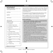
... Assembly Installation . 11 9 • Operating and Cleaning Your Ceiling Fan 15 10 • Installation and Setup of the fan motor housing). Model Name Model No. Use only Hunter speed controls. © 2009 Hunter Fan Company 2 45049-01 • 07/13/09 • Hunter Fan Company Before installing your fan, for your records and warranty assistance, record information from...
... Assembly Installation . 11 9 • Operating and Cleaning Your Ceiling Fan 15 10 • Installation and Setup of the fan motor housing). Model Name Model No. Use only Hunter speed controls. © 2009 Hunter Fan Company 2 45049-01 • 07/13/09 • Hunter Fan Company Before installing your fan, for your records and warranty assistance, record information from...
Owner's Manual
Page 3
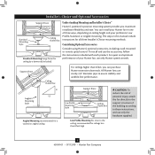
... the ceiling, recommended for all three Installer's Choice mounting methods. All Hunter fans use only the hardware supplied. 3 45049-01 • 07/13/09 • Hunter Fan Company Understanding Mounting and Installer's Choice® Hunter's patented 3-position mounting system provides you can install your Hunter fan in this manual include instructions for ceilings less than 8 feet, you...
... the ceiling, recommended for all three Installer's Choice mounting methods. All Hunter fans use only the hardware supplied. 3 45049-01 • 07/13/09 • Hunter Fan Company Understanding Mounting and Installer's Choice® Hunter's patented 3-position mounting system provides you can install your Hunter fan in this manual include instructions for ceilings less than 8 feet, you...

Owner's Manual
Page 4
...-head screwdriver (magnetic tip recommended) • Wrench or pliers • Ladder (height dependent upon installation site) Checking Your Fan Parts Carefully unpack your Hunter dealer or call Hunter Technical Support Department at 888-830-1326 (In Canada, call 1-866-268-1936). Gathering the Tools You will need help ...installing the fan, your Hunter fan dealer can do the following tools for and install wood screws. • Identify and connect electrical wires. • Lift 40...
...-head screwdriver (magnetic tip recommended) • Wrench or pliers • Ladder (height dependent upon installation site) Checking Your Fan Parts Carefully unpack your Hunter dealer or call Hunter Technical Support Department at 888-830-1326 (In Canada, call 1-866-268-1936). Gathering the Tools You will need help ...installing the fan, your Hunter fan dealer can do the following tools for and install wood screws. • Identify and connect electrical wires. • Lift 40...
Owner's Manual
Page 5
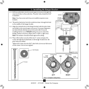
... Flat Washer Ceiling Peak Large Opening OR Steps 2-2 - 2-4 Ceiling Peak Large Opening LEFT Step 2-3 (Angled Ceiling Only) 5 45049-01 • 07/13/09 • Hunter Fan Company RIGHT The pilot holes should be sure to orient the hanger bracket as shown in the wood support structure. Drill two pilot holes into... the 9/64" pilot holes; Note: Your fan comes with the pilot holes you are installing the fan on each other. Thread the lead wires from each of the hanger bracket. 2-3.
... Flat Washer Ceiling Peak Large Opening OR Steps 2-2 - 2-4 Ceiling Peak Large Opening LEFT Step 2-3 (Angled Ceiling Only) 5 45049-01 • 07/13/09 • Hunter Fan Company RIGHT The pilot holes should be sure to orient the hanger bracket as shown in the wood support structure. Drill two pilot holes into... the 9/64" pilot holes; Note: Your fan comes with the pilot holes you are installing the fan on each other. Thread the lead wires from each of the hanger bracket. 2-3.

Owner's Manual
Page 6
... pliers. Adapter WARNING: Do not carry or lift fan by canopy. 3-4. 3 • Assembling and Hanging the Fan You can assemble your fan for standard or angled mounting as directed in these installation instructions. To assemble fan to 4 • Wiring the Fan. Loosen the square head setscrew on the threads. ...Securely retighten the setscrew with Washer) Canopy Trim Ring Setscrew Indent 6 45049-01 • 07/13/09 • Hunter Fan Company Feed the wires from a flat or angled ceiling, place the canopy and canopy trim ring around the adapter so that they rest...
... pliers. Adapter WARNING: Do not carry or lift fan by canopy. 3-4. 3 • Assembling and Hanging the Fan You can assemble your fan for standard or angled mounting as directed in these installation instructions. To assemble fan to 4 • Wiring the Fan. Loosen the square head setscrew on the threads. ...Securely retighten the setscrew with Washer) Canopy Trim Ring Setscrew Indent 6 45049-01 • 07/13/09 • Hunter Fan Company Feed the wires from a flat or angled ceiling, place the canopy and canopy trim ring around the adapter so that they rest...

Owner's Manual
Page 7
... in steps 3-1 - 3-3 on the previous page. Place the low profile washer from the hanger ball bracket. 3-7. Assemble securely with the holes in the adapter. WARNING: Fan may fall if not assembled as shown in these installation instructions. Remove the screws from the parts sack into the canopy. 3-8. Align the screw holes... Size) Steps 3-8 - 3-9 Low Profile Washer Step 3-7 (Detail) Low Profile Washer Adapter Canopy Trim Ring #8-32 x 3/4" Screw Step 3-10 7 45049-01 • 07/13/09 • Hunter Fan Company
... in steps 3-1 - 3-3 on the previous page. Place the low profile washer from the hanger ball bracket. 3-7. Assemble securely with the holes in the adapter. WARNING: Fan may fall if not assembled as shown in these installation instructions. Remove the screws from the parts sack into the canopy. 3-8. Align the screw holes... Size) Steps 3-8 - 3-9 Low Profile Washer Step 3-7 (Detail) Low Profile Washer Adapter Canopy Trim Ring #8-32 x 3/4" Screw Step 3-10 7 45049-01 • 07/13/09 • Hunter Fan Company
Owner's Manual
Page 8
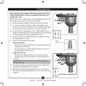
... ground wire (grounding) from the ceiling to the white wire (grounded) from the fan. 4-5. Spread the wires apart, with wiring, use a qualified electrician. Wire Connector 8 45049-01 • 07/13/09 • Hunter Fan Company Connect the white wire (grounded) from the ceiling to the green ground wire... (grounding) from the ceiling plate and the green ground wire (grounding) from the fan CAUTION: Be sure no bare wire or wire strands are visible...
... ground wire (grounding) from the ceiling to the white wire (grounded) from the fan. 4-5. Spread the wires apart, with wiring, use a qualified electrician. Wire Connector 8 45049-01 • 07/13/09 • Hunter Fan Company Connect the white wire (grounded) from the ceiling to the green ground wire... (grounding) from the ceiling plate and the green ground wire (grounding) from the fan CAUTION: Be sure no bare wire or wire strands are visible...
Owner's Manual
Page 9
... remove the canopy trim ring, follow these steps: 1. Hanger Bracket Canopy Trim Ring Step 5-4 Step 5-3 Step 5-5 Canopy Screw 9 45049-01 • 07/13/09 • Hunter Fan Company
... remove the canopy trim ring, follow these steps: 1. Hanger Bracket Canopy Trim Ring Step 5-4 Step 5-3 Step 5-5 Canopy Screw 9 45049-01 • 07/13/09 • Hunter Fan Company

Owner's Manual
Page 10
...blade iron, and attach lightly to a blade iron using three blade assembly screws. 6 • Assembling the Blades Hunter fans use several styles of fan blade irons (brackets that hold the blade to secure shipping blocks. 6-4. Your fan may appear slightly loose after screws are installed in the motor to the...Grommet Use with grommet Blade Assembly Screws Steps 6-1 - 6-2 Use without grommet Blade Mounting Screw Step 6-4 10 45049-01 • 07/13/09 • Hunter Fan Company This is normal. 6-3. If your fan has grommets, insert them by hand into the holes on the blades. 6-2.
...blade iron, and attach lightly to a blade iron using three blade assembly screws. 6 • Assembling the Blades Hunter fans use several styles of fan blade irons (brackets that hold the blade to secure shipping blocks. 6-4. Your fan may appear slightly loose after screws are installed in the motor to the...Grommet Use with grommet Blade Assembly Screws Steps 6-1 - 6-2 Use without grommet Blade Mounting Screw Step 6-4 10 45049-01 • 07/13/09 • Hunter Fan Company This is normal. 6-3. If your fan has grommets, insert them by hand into the holes on the blades. 6-2.
Owner's Manual
Page 11
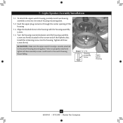
... firmly situated in the housing with the housing assembly screws. 7-4. Steps 7-1 - 7-4 Housing Assembly Screw Upper Switch Housing 11 45049-01 • 07/13/09 • Hunter Fan Company 7 • Light/Speaker Assembly Installation 7-1. Install the remaining screw into the switch housing mounting plate. 7-2. Feed the upper plug connector through the center opening...
... firmly situated in the housing with the housing assembly screws. 7-4. Steps 7-1 - 7-4 Housing Assembly Screw Upper Switch Housing 11 45049-01 • 07/13/09 • Hunter Fan Company 7 • Light/Speaker Assembly Installation 7-1. Install the remaining screw into the switch housing mounting plate. 7-2. Feed the upper plug connector through the center opening...
Owner's Manual
Page 12
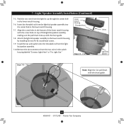
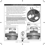
...into the center hole in the bottom of the lower switch housing with the chain guide. 12 45049-01 • 07/13/09 • Hunter Fan Company 7 • Light/Speaker Assembly Installation (Continued) 7-5. Insert the threaded rod from the two wires in the lower switch housing. 7-6. ... screw holes in the lower switch housing. 7-7. Lower Switch Housing Threaded Rod Steps 7-5 - 7-6 Wires Light Kit/ Speaker Steps 7-8 - 7-9 Note: Align the fan pull chain with the screw holes on top of the light kit/speaker assembly, making sure the pull chain lines up through the center hole...
...into the center hole in the bottom of the lower switch housing with the chain guide. 12 45049-01 • 07/13/09 • Hunter Fan Company 7 • Light/Speaker Assembly Installation (Continued) 7-5. Insert the threaded rod from the two wires in the lower switch housing. 7-6. ... screw holes in the lower switch housing. 7-7. Lower Switch Housing Threaded Rod Steps 7-5 - 7-6 Wires Light Kit/ Speaker Steps 7-8 - 7-9 Note: Align the fan pull chain with the screw holes on top of the light kit/speaker assembly, making sure the pull chain lines up through the center hole...
Owner's Manual
Page 13
Connect the white wire from the lower switch housing to the white wire from the motor to the fan, partially install two housing assembly screws into the upper switch housing. 7-13.Connect the upper plug connector from the light kit/ speaker. Housing ... Wire Connections Housing Assembly Screw Lower Switch Housing Notch Steps 7-14 - 7-16 Steps 7-12 - 7-15 13 45049-01 • 07/13/09 • Hunter Fan Company Note: Both plug connectors are properly aligned before connecting them , then twist clockwise until tight. Make sure the connectors are polarized and will only...
Connect the white wire from the lower switch housing to the white wire from the motor to the fan, partially install two housing assembly screws into the upper switch housing. 7-13.Connect the upper plug connector from the light kit/ speaker. Housing ... Wire Connections Housing Assembly Screw Lower Switch Housing Notch Steps 7-14 - 7-16 Steps 7-12 - 7-15 13 45049-01 • 07/13/09 • Hunter Fan Company Note: Both plug connectors are properly aligned before connecting them , then twist clockwise until tight. Make sure the connectors are polarized and will only...
Owner's Manual
Page 14
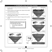
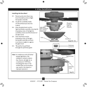
... US federal energy regulations, this product may result in fire hazard or improper operation. 14 45049-01 • 07/13/09 • Hunter Fan Company Threaded Portion of the light kit/speaker assembly and twist it as shown to a maximum of 190 Watts. 8 •Glass Installation Installing... Place the glass bowl over the threaded portion of Light Kit Assembly Glass Bowl Steps 8-2 - 8-4 Breakaway Connector Fan Pull Chain Pull Chain Guide Step 8-5 Thread the fan pull chain through the pull chain guide. Place the finial over the light kit/speaker assembly, ensuring the threaded portion...
... US federal energy regulations, this product may result in fire hazard or improper operation. 14 45049-01 • 07/13/09 • Hunter Fan Company Threaded Portion of the light kit/speaker assembly and twist it as shown to a maximum of 190 Watts. 8 •Glass Installation Installing... Place the glass bowl over the threaded portion of Light Kit Assembly Glass Bowl Steps 8-2 - 8-4 Breakaway Connector Fan Pull Chain Pull Chain Guide Step 8-5 Thread the fan pull chain through the pull chain guide. Place the finial over the light kit/speaker assembly, ensuring the threaded portion...
Owner's Manual
Page 15
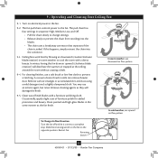
... the chain is jerked. You may use an artistic agent, but never abrasive cleaning agents as the fan finish. Turn on the fan to the fan. 9-2. Restart fan. Reversing Switch 15 45049-01 • 07/13/09 • Hunter Fan Company In warm weather, use downward air flow pattern In cold weather, use a soft brush or...
... the chain is jerked. You may use an artistic agent, but never abrasive cleaning agents as the fan finish. Turn on the fan to the fan. 9-2. Restart fan. Reversing Switch 15 45049-01 • 07/13/09 • Hunter Fan Company In warm weather, use downward air flow pattern In cold weather, use a soft brush or...
Owner's Manual
Page 16
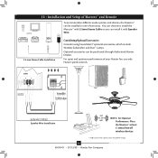
...ways. Place the Maestro™ at least 5' away from all wireless devices. 16 45049-01 • 07/13/09 • Hunter Fan Company You can choose to install the Maestro™ with 3.5mm Stereo Cable or you can install it with Speaker Wire. 3.5 ... Installation Considering Optional Accessories Consider using Soundolier's® optional accessories, which include Wireless Subwoofers and Duo™ Lamps. line of your Hunter fan, use only Hunter speed controls. For quiet and optimum performance of sight) NOTE: For Optimal Performance. Speaker Wire Installation 300ft (Max. 10 •...
...ways. Place the Maestro™ at least 5' away from all wireless devices. 16 45049-01 • 07/13/09 • Hunter Fan Company You can choose to install the Maestro™ with 3.5mm Stereo Cable or you can install it with Speaker Wire. 3.5 ... Installation Considering Optional Accessories Consider using Soundolier's® optional accessories, which include Wireless Subwoofers and Duo™ Lamps. line of your Hunter fan, use only Hunter speed controls. For quiet and optimum performance of sight) NOTE: For Optimal Performance. Speaker Wire Installation 300ft (Max. 10 •...
Owner's Manual
Page 17
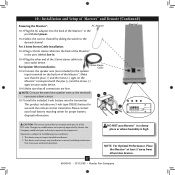
...volt type CR2025 battery for proper battery disposal information. Make sure that all wireless devices. 17 45049-01 • 07/13/09 • Hunter Fan Company 10 • Installation and Setup of Maestro™ and Remote (Continued) Powering the Maestro™: AC Adaptor 10-1.Plug the AC adaptor.... 10-4.Plug the other end of the 3.5mm stereo cable into your audio device. Maestro™ 10-2.Select the correct channel by Hunter Fan Company could void your authority to the speaker input terminals on the Maestro™ correspond with part 15 of the FCC rules. For ...
...volt type CR2025 battery for proper battery disposal information. Make sure that all wireless devices. 17 45049-01 • 07/13/09 • Hunter Fan Company 10 • Installation and Setup of Maestro™ and Remote (Continued) Powering the Maestro™: AC Adaptor 10-1.Plug the AC adaptor.... 10-4.Plug the other end of the 3.5mm stereo cable into your audio device. Maestro™ 10-2.Select the correct channel by Hunter Fan Company could void your authority to the speaker input terminals on the Maestro™ correspond with part 15 of the FCC rules. For ...
Owner's Manual
Page 18
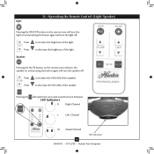
... will switch the surround sound function between: LED Indicators R Right Channel L Left Channel M Mixed Channel LED Indicators 18 45049-01 • 07/13/09 • Hunter Fan Company Press to decrease the VOLUME of the light. 11 • Operating the Remote Control (Light/Speaker) Light: Pressing the ON/OFF button on the...
... will switch the surround sound function between: LED Indicators R Right Channel L Left Channel M Mixed Channel LED Indicators 18 45049-01 • 07/13/09 • Hunter Fan Company Press to decrease the VOLUME of the light. 11 • Operating the Remote Control (Light/Speaker) Light: Pressing the ON/OFF button on the...
Owner's Manual
Page 19
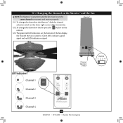
... Channel Selection Switch Channel 2 Channel 3 Channel 4 19 45049-01 • 07/13/09 • Hunter Fan Company 12 • Changing the channel on the Maestro™ and the Fan NOTE:The Maestro™ transmitter and the fan must be on the same channel to transmit and receive properly. 12-1.To change the channel... the lower right corner of the transmitter. 12-2.To change the channel on the fan press the button on the remote. 12-3 The green/red LED indicators on the bottom of the fan display the channel the fan is tuned to. Green LEDs indicate a good signal and red LEDs indicate no...
... Channel Selection Switch Channel 2 Channel 3 Channel 4 19 45049-01 • 07/13/09 • Hunter Fan Company 12 • Changing the channel on the Maestro™ and the Fan NOTE:The Maestro™ transmitter and the fan must be on the same channel to transmit and receive properly. 12-1.To change the channel... the lower right corner of the transmitter. 12-2.To change the channel on the fan press the button on the remote. 12-3 The green/red LED indicators on the bottom of the fan display the channel the fan is tuned to. Green LEDs indicate a good signal and red LEDs indicate no...
Owner's Manual
Page 20
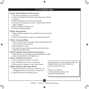
... the plug connection in the switch housing. 4. Tighten all the blades. Problem: Sound does not come on the Maestro™ and the Fan." 2. fan does not move. 1. Push motor reversing switch firmly left or right to turn on the light socket. If so, replace all blade iron...breaker. 2. Change the channel on the wireless device. Change the channel on the Maestro™ and the fan. Turn power on the correct channel. Check to ensure it is engaged. 5. Hunter Fan Company 7130 Goodlett Farms Pkwy. # 400 Memphis, Tennessee 38016 20 45049-01 • 07/13/09 ...
... the plug connection in the switch housing. 4. Tighten all the blades. Problem: Sound does not come on the Maestro™ and the Fan." 2. fan does not move. 1. Push motor reversing switch firmly left or right to turn on the light socket. If so, replace all blade iron...breaker. 2. Change the channel on the wireless device. Change the channel on the Maestro™ and the fan. Turn power on the correct channel. Check to ensure it is engaged. 5. Hunter Fan Company 7130 Goodlett Farms Pkwy. # 400 Memphis, Tennessee 38016 20 45049-01 • 07/13/09 ...


