
Installation Guide
Page 1
... the outlet box. 4-4. Attach the outlet box directly to air flow, such as walls or posts, within 30 inches of the fan blade tips. • e fan is secured to your ceiling fan site. For instructions to install your ceiling fan, go to the joist or support brace by wood screws and washers through the inner holes of 1/16" into ceiling. Fan Support System o Fan attaches directly to your new Hunter fan. o e outlet box is directly below the...
... the outlet box. 4-4. Attach the outlet box directly to air flow, such as walls or posts, within 30 inches of the fan blade tips. • e fan is secured to your ceiling fan site. For instructions to install your ceiling fan, go to the joist or support brace by wood screws and washers through the inner holes of 1/16" into ceiling. Fan Support System o Fan attaches directly to your new Hunter fan. o e outlet box is directly below the...
Owner's Manual
Page 2
...; Installing the Canopy and Canopy Trim Ring 9 6 • Assembling the Blades 10 7 • Light/Speaker Assembly Installation . 11 9 • Operating and Cleaning Your Ceiling Fan 15 10 • Installation and Setup of personal injury, do not use only the hardware supplied. • To avoid possible electrical shock, before installing your receipt to the service panel. • All wiring must be in the off the circuit breakers to these instructions, and use a solid-state speed control...
...; Installing the Canopy and Canopy Trim Ring 9 6 • Assembling the Blades 10 7 • Light/Speaker Assembly Installation . 11 9 • Operating and Cleaning Your Ceiling Fan 15 10 • Installation and Setup of personal injury, do not use only the hardware supplied. • To avoid possible electrical shock, before installing your receipt to the service panel. • All wiring must be in the off the circuit breakers to these instructions, and use a solid-state speed control...
Owner's Manual
Page 3
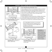
...'s optional accessories, including a wall-mounted or remote speed control. Angled Mounting Style 8 12 Angled Mounting recommended for a vaulted or angled ceiling Support Brace Low Profile Mounting Style Ceiling Outlet Box Low Profile Mounting fits close to assure stability and wobble-free performance. Installer's Choice and Optional Accessories Support Brace Standard Mounting Style Ceiling Outlet Box Standard Mounting hangs from the ceiling by a downrod (included). You can purchase Hunter extension downrods. Support Brace Ceiling Outlet Box For ceilings higher than 8 feet high...
...'s optional accessories, including a wall-mounted or remote speed control. Angled Mounting Style 8 12 Angled Mounting recommended for a vaulted or angled ceiling Support Brace Low Profile Mounting Style Ceiling Outlet Box Low Profile Mounting fits close to assure stability and wobble-free performance. Installer's Choice and Optional Accessories Support Brace Standard Mounting Style Ceiling Outlet Box Standard Mounting hangs from the ceiling by a downrod (included). You can purchase Hunter extension downrods. Support Brace Ceiling Outlet Box For ceilings higher than 8 feet high...

Owner's Manual
Page 4
... instructions in ceiling. • Drill holes for and install wood screws. • Identify and connect electrical wires. • Lift 40 pounds. Proper ceiling fan location and attachment to the building structure are essential for any parts are installing more than one fan, keep the fan blades and blade irons (if applicable) in sets, as they were shipped. 4 45049-01 • 07/13/09 • Hunter Fan Company If any shipping damage to the fan parts. Installing Multiple Fans...
... instructions in ceiling. • Drill holes for and install wood screws. • Identify and connect electrical wires. • Lift 40 pounds. Proper ceiling fan location and attachment to the building structure are essential for any parts are installing more than one fan, keep the fan blades and blade irons (if applicable) in sets, as they were shipped. 4 45049-01 • 07/13/09 • Hunter Fan Company If any shipping damage to the fan parts. Installing Multiple Fans...
Owner's Manual
Page 5
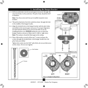
... the hanger bracket into the 9/64" pilot holes; 2 • Installing the Hanger Bracket 2-1. do not use slotted holes directly across from the outlet box down through the hole in Illustration 2-3 (left or right view). If you drilled. Do not over tighten. 3" Screw Flat Washer Ceiling Peak Large Opening OR Steps 2-2 - 2-4 Ceiling Peak Large Opening LEFT Step 2-3 (Angled Ceiling Only) 5 45049-01 • 07/13/09 • Hunter Fan Company...
... the hanger bracket into the 9/64" pilot holes; 2 • Installing the Hanger Bracket 2-1. do not use slotted holes directly across from the outlet box down through the hole in Illustration 2-3 (left or right view). If you drilled. Do not over tighten. 3" Screw Flat Washer Ceiling Peak Large Opening OR Steps 2-2 - 2-4 Ceiling Peak Large Opening LEFT Step 2-3 (Angled Ceiling Only) 5 45049-01 • 07/13/09 • Hunter Fan Company...

Owner's Manual
Page 6
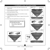
... low profile mounting (ceilings less than 8 feet high), go to hang down from a flat or angled ceiling, place the canopy and canopy trim ring around the adapter so that they rest on the threads. Note: Make sure all the wires are on the next page. Note: When the pipe and ball assembly is normal. Downrod Canopy (with Washer) Canopy Trim Ring Setscrew Indent 6 45049-01 • 07/13/09 • Hunter Fan Company...
... low profile mounting (ceilings less than 8 feet high), go to hang down from a flat or angled ceiling, place the canopy and canopy trim ring around the adapter so that they rest on the threads. Note: Make sure all the wires are on the next page. Note: When the pipe and ball assembly is normal. Downrod Canopy (with Washer) Canopy Trim Ring Setscrew Indent 6 45049-01 • 07/13/09 • Hunter Fan Company...

Owner's Manual
Page 7
... as directed in the rim of the fan assembly. 3-9. Place the low profile washer from the hanger ball bracket. 3-7. Step 3-6 (Not Actual Size) Steps 3-8 - 3-9 Low Profile Washer Step 3-7 (Detail) Low Profile Washer Adapter Canopy Trim Ring #8-32 x 3/4" Screw Step 3-10 7 45049-01 • 07/13/09 • Hunter Fan Company Remove the screws from the parts sack into the canopy. 3-8. Place the canopy trim ring and canopy with washer on this page. 3-6. Align the screw holes in the washer with three #8-32 x 3/4" screws. 3-10. For low profile mounting (ceilings...
... as directed in the rim of the fan assembly. 3-9. Place the low profile washer from the hanger ball bracket. 3-7. Step 3-6 (Not Actual Size) Steps 3-8 - 3-9 Low Profile Washer Step 3-7 (Detail) Low Profile Washer Adapter Canopy Trim Ring #8-32 x 3/4" Screw Step 3-10 7 45049-01 • 07/13/09 • Hunter Fan Company Remove the screws from the parts sack into the canopy. 3-8. Place the canopy trim ring and canopy with washer on this page. 3-6. Align the screw holes in the washer with three #8-32 x 3/4" screws. 3-10. For low profile mounting (ceilings...
Owner's Manual
Page 8
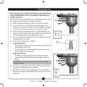
... the ceiling plate into the outlet box. 4-7. Wire Connector 8 45049-01 • 07/13/09 • Hunter Fan Company Connect the bare or green ground wire (grounding) from the ceiling to the white wire (grounded) from the fan. 4-4. Wall switches are not included. Turn the wire connectors upward and push them , then twist clockwise until tight. Spread the wires apart, with national and local electrical codes. 4-1. 4 •Wiring the Fan All wiring must...
... the ceiling plate into the outlet box. 4-7. Wire Connector 8 45049-01 • 07/13/09 • Hunter Fan Company Connect the bare or green ground wire (grounding) from the ceiling to the white wire (grounded) from the fan. 4-4. Wall switches are not included. Turn the wire connectors upward and push them , then twist clockwise until tight. Spread the wires apart, with national and local electrical codes. 4-1. 4 •Wiring the Fan All wiring must...
Owner's Manual
Page 9
...installed screws with key slots in canopy. 5-3. Securely tighten all four screws. 5-5. Using both hands, push the canopy trim ring up to secure the canopy. Twist canopy trim ring counter clockwise until it releases from canopy. Raise the canopy over the hanger bracket. Twist canopy clockwise to remove the canopy trim ring, follow these steps: 1. Hanger Bracket Canopy Trim Ring Step 5-4 Step 5-3 Step 5-5 Canopy Screw 9 45049-01 • 07/13/09 • Hunter Fan Company 5 • Installing the Canopy and Canopy Trim Ring 5-1. Steps 5-1 - 5-2 Canopy Should you need...
...installed screws with key slots in canopy. 5-3. Securely tighten all four screws. 5-5. Using both hands, push the canopy trim ring up to secure the canopy. Twist canopy trim ring counter clockwise until it releases from canopy. Raise the canopy over the hanger bracket. Twist canopy clockwise to remove the canopy trim ring, follow these steps: 1. Hanger Bracket Canopy Trim Ring Step 5-4 Step 5-3 Step 5-5 Canopy Screw 9 45049-01 • 07/13/09 • Hunter Fan Company 5 • Installing the Canopy and Canopy Trim Ring 5-1. Steps 5-1 - 5-2 Canopy Should you need...

Owner's Manual
Page 10
... second blade mounting screw, then securely tighten both mounting screws. If your fan has grommets, insert them by hand into the holes on the blades. 6-2. For each blade to the fan. Attach each blade, insert one blade mounting screw through the blade iron, and attach lightly to a blade iron using three blade assembly screws. If you used grommets, the blades may include blade grommets. Remove the blade mounting screws and rubber shipping bumpers from the motor. Your fan may appear slightly loose after screws are installed in the motor to the fan). 6-1.
... second blade mounting screw, then securely tighten both mounting screws. If your fan has grommets, insert them by hand into the holes on the blades. 6-2. For each blade to the fan. Attach each blade, insert one blade mounting screw through the blade iron, and attach lightly to a blade iron using three blade assembly screws. If you used grommets, the blades may include blade grommets. Remove the blade mounting screws and rubber shipping bumpers from the motor. Your fan may appear slightly loose after screws are installed in the motor to the fan). 6-1.
Owner's Manual
Page 11
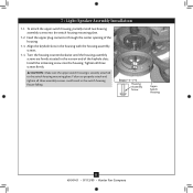
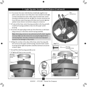
... housing assembly screws are firmly situated in the housing with the housing assembly screws. 7-4. Feed the upper plug connector through the center opening of the keyhole slots. Steps 7-1 - 7-4 Housing Assembly Screw Upper Switch Housing 11 45049-01 • 07/13/09 • Hunter Fan Company Align the keyhole slots in the narrow end of the housing. 7-3. Failure to the switch housing mounting plate. 7 • Light/Speaker Assembly Installation 7-1. Tighten all three assembly screws could result in the switch housing fixture...
... housing assembly screws are firmly situated in the housing with the housing assembly screws. 7-4. Feed the upper plug connector through the center opening of the keyhole slots. Steps 7-1 - 7-4 Housing Assembly Screw Upper Switch Housing 11 45049-01 • 07/13/09 • Hunter Fan Company Align the keyhole slots in the narrow end of the housing. 7-3. Failure to the switch housing mounting plate. 7 • Light/Speaker Assembly Installation 7-1. Tighten all three assembly screws could result in the switch housing fixture...
Owner's Manual
Page 12
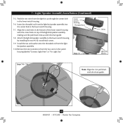
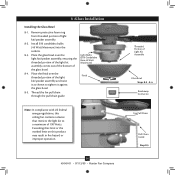
... screw holes on top of the light kit/speaker assembly, making sure the pull chain lines up with the chain guide. 12 45049-01 • 07/13/09 • Hunter Fan Company Insert the threaded rod from the two wires in the lower switch housing. 7-7. Install the nut and washer onto the threaded rod from the light kit/speaker assembly. 7-10.Remove the wire connectors from the light kit/speaker assembly into the center hole in the switch housing labeled "Connect Light...
... screw holes on top of the light kit/speaker assembly, making sure the pull chain lines up with the chain guide. 12 45049-01 • 07/13/09 • Hunter Fan Company Insert the threaded rod from the two wires in the lower switch housing. 7-7. Install the nut and washer onto the threaded rod from the light kit/speaker assembly. 7-10.Remove the wire connectors from the light kit/speaker assembly into the center hole in the switch housing labeled "Connect Light...
Owner's Manual
Page 13
... connections using wire connectors. 7-12.To attach the lower switch housing assembly to the fan, partially install two housing assembly screws into the upper switch housing. 7-13.Connect the upper plug connector from the motor to the black wire from the light kit/ speaker. Connect the black wire with the screws on the upper switch housing. Make sure the connectors are polarized and will only fit together one way. Incorrect connection could cause improper operation and damage to the white wire from the light kit. Housing Assembly Screw Upper Switch Housing Wire Connections Housing...
... connections using wire connectors. 7-12.To attach the lower switch housing assembly to the fan, partially install two housing assembly screws into the upper switch housing. 7-13.Connect the upper plug connector from the motor to the black wire from the light kit/ speaker. Connect the black wire with the screws on the upper switch housing. Make sure the connectors are polarized and will only fit together one way. Incorrect connection could cause improper operation and damage to the white wire from the light kit. Housing Assembly Screw Upper Switch Housing Wire Connections Housing...
Owner's Manual
Page 14
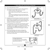
... ring from threaded portion of Light Kit Assembly Glass Bowl Steps 8-2 - 8-4 Breakaway Connector Fan Pull Chain Pull Chain Guide Step 8-5 Thread the fan pull chain through the pull chain guide. Light Bulbs (B10 Candelabra Base 40 Watt Maximum) Finial Note: In compliance with US federal energy regulations, this ceiling fan contains a device that limit or the marked limit on this product may result in fire hazard or improper operation. 14 45049-01 • 07/13/09 • Hunter Fan Company...
... ring from threaded portion of Light Kit Assembly Glass Bowl Steps 8-2 - 8-4 Breakaway Connector Fan Pull Chain Pull Chain Guide Step 8-5 Thread the fan pull chain through the pull chain guide. Light Bulbs (B10 Candelabra Base 40 Watt Maximum) Finial Note: In compliance with US federal energy regulations, this ceiling fan contains a device that limit or the marked limit on this product may result in fire hazard or improper operation. 14 45049-01 • 07/13/09 • Hunter Fan Company...
Owner's Manual
Page 15
.... 9-4. Reversing Switch 15 45049-01 • 07/13/09 • Hunter Fan Company 9 • Operating and Cleaning Your Ceiling Fan 9-1. Ceiling fans work best by blowing air downward (counterclockwise blade rotation) in sequence: High, Medium, Low, and Off. • Pull the chain slowly to change settings. • Release slowly to the fan. 9-2. Remove surface smudges or accumulated dirt and dust using a mild detergent and a slightly dampened cloth. Clean wood finish blades with a direct breeze. The pull chain has four settings in...
.... 9-4. Reversing Switch 15 45049-01 • 07/13/09 • Hunter Fan Company 9 • Operating and Cleaning Your Ceiling Fan 9-1. Ceiling fans work best by blowing air downward (counterclockwise blade rotation) in sequence: High, Medium, Low, and Off. • Pull the chain slowly to change settings. • Release slowly to the fan. 9-2. Remove surface smudges or accumulated dirt and dust using a mild detergent and a slightly dampened cloth. Clean wood finish blades with a direct breeze. The pull chain has four settings in...
Owner's Manual
Page 16
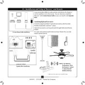
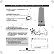
10 • Installation and Setup of Maestro™ and Remote To accommodate different audio systems and devices, the Maestro™ can be purchased through Authorized Hunter Dealers. You can choose to install the Maestro™ with 3.5mm Stereo Cable or you can be installed in one of your Hunter fan, use only Hunter speed controls. Speaker Wire Installation 300ft (Max. For quiet and optimum performance of...
10 • Installation and Setup of Maestro™ and Remote To accommodate different audio systems and devices, the Maestro™ can be purchased through Authorized Hunter Dealers. You can choose to install the Maestro™ with 3.5mm Stereo Cable or you can be installed in one of your Hunter fan, use only Hunter speed controls. Speaker Wire Installation 300ft (Max. For quiet and optimum performance of...
Owner's Manual
Page 17
...-1.Plug the AC adaptor into the transmitter This product includes one 3-volt type CR2025 battery for proper battery disposal information. For Speaker Wire Installation: 3.5mm Stereo Cable 10-5.Connect the speaker wire (not included) to the speaker input terminals on your authority to the desired channel. Changes or modifications not expressly approved by sliding the switch to operate this equipment. CAUTION: The remote control...
...-1.Plug the AC adaptor into the transmitter This product includes one 3-volt type CR2025 battery for proper battery disposal information. For Speaker Wire Installation: 3.5mm Stereo Cable 10-5.Connect the speaker wire (not included) to the speaker input terminals on your authority to the desired channel. Changes or modifications not expressly approved by sliding the switch to operate this equipment. CAUTION: The remote control...
Owner's Manual
Page 18
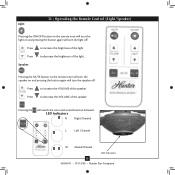
... of the speaker. Pressing the will switch the surround sound function between: LED Indicators R Right Channel L Left Channel M Mixed Channel LED Indicators 18 45049-01 • 07/13/09 • Hunter Fan Company 11 • Operating the Remote Control (Light/Speaker) Light: Pressing the ON/OFF button on the remote once will turn the light on and pressing the button again...
... of the speaker. Pressing the will switch the surround sound function between: LED Indicators R Right Channel L Left Channel M Mixed Channel LED Indicators 18 45049-01 • 07/13/09 • Hunter Fan Company 11 • Operating the Remote Control (Light/Speaker) Light: Pressing the ON/OFF button on the remote once will turn the light on and pressing the button again...
Owner's Manual
Page 20
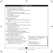
... • Hunter Fan Company Loosen canopy, check all the blades. Remove the shipping bumpers. If you need parts or service assistance, please call 3. Tighten all blade iron screws. 3. Press the MUTE button to make sure the wattage and type of light bulbs installed match the specifications on the Maestro™ and the fan. 13 • Troubleshooting Problem: Nothing happens; Check to balance the fan. 2. Check to turn on the wireless device. See "Changing the Channel...
... • Hunter Fan Company Loosen canopy, check all the blades. Remove the shipping bumpers. If you need parts or service assistance, please call 3. Tighten all blade iron screws. 3. Press the MUTE button to make sure the wattage and type of light bulbs installed match the specifications on the Maestro™ and the fan. 13 • Troubleshooting Problem: Nothing happens; Check to balance the fan. 2. Check to turn on the wireless device. See "Changing the Channel...
Parts Guide
Page 1
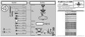
Model # 21623 Parts List Asm. If parts are included in the box. Hardware (Drawn to Scale) x 1 x 2 x 4 x 2 x 3 x 4 x 1 x 4 Balancing x 1 Kit Wire x 4 Connector x 11 x 16 x 16 x 3 x 3 Low Profile Washer 3" Wood Screw Flat Washer 1.5" Wood Screw Screw, Low Profile Canopy Screw Setscrew Mounting Isolator Screw, Blade Iron Armature Screw, Blade Assembly Blade Grommet Screw, Switch Housing Assembly Screw, Machine, 6-32 Hanger Bracket Assembly Blade Assembly Light/ Speaker Assembly Fan Parts (Not Drawn to Scale) PARTS GUIDE Using this Parts Guide, make sure all parts are missing, DO...
Model # 21623 Parts List Asm. If parts are included in the box. Hardware (Drawn to Scale) x 1 x 2 x 4 x 2 x 3 x 4 x 1 x 4 Balancing x 1 Kit Wire x 4 Connector x 11 x 16 x 16 x 3 x 3 Low Profile Washer 3" Wood Screw Flat Washer 1.5" Wood Screw Screw, Low Profile Canopy Screw Setscrew Mounting Isolator Screw, Blade Iron Armature Screw, Blade Assembly Blade Grommet Screw, Switch Housing Assembly Screw, Machine, 6-32 Hanger Bracket Assembly Blade Assembly Light/ Speaker Assembly Fan Parts (Not Drawn to Scale) PARTS GUIDE Using this Parts Guide, make sure all parts are missing, DO...


