
Installation Guide
Page 1
... associated wall switch location are aligned with the joist or support brace. 4-3. If your new Hunter fan. Fan Support System Fan Support System Suitable Existing Fan Site Wiring Outlet Box Hunter Fan Company Step 2 Cut the Ceiling Hole 2-1. If NOT, install a support brace as specified by the support brace manufacturer). Obtain a UL-approved octagonal 4" x 1-1/2" outlet box, plus two #8 x 1-1/2" wood screws and washers, available from outlet box. CAUTION: All wiring must be in contact with 2 • Installing the Ceiling Plate. o Six inches...
... associated wall switch location are aligned with the joist or support brace. 4-3. If your new Hunter fan. Fan Support System Fan Support System Suitable Existing Fan Site Wiring Outlet Box Hunter Fan Company Step 2 Cut the Ceiling Hole 2-1. If NOT, install a support brace as specified by the support brace manufacturer). Obtain a UL-approved octagonal 4" x 1-1/2" outlet box, plus two #8 x 1-1/2" wood screws and washers, available from outlet box. CAUTION: All wiring must be in contact with 2 • Installing the Ceiling Plate. o Six inches...
Owner's Manual
Page 2
...; To reduce the risk of your Hunter fan, use the accessories, follow the instructions included with this manual include specific instructions for installing and operating your Hunter fan in one fan, keep the fan blades in shipment, return all the blades for replacement. 2 ® Your new Hunter® ceiling fan is recommended. We are unfamiliar with wiring, you can purchase Hunter extension downrods. Model Name Catalog/Model No Serial No Date Purchased Where Purchased Please also attach your choice. If...
...; To reduce the risk of your Hunter fan, use the accessories, follow the instructions included with this manual include specific instructions for installing and operating your Hunter fan in one fan, keep the fan blades in shipment, return all the blades for replacement. 2 ® Your new Hunter® ceiling fan is recommended. We are unfamiliar with wiring, you can purchase Hunter extension downrods. Model Name Catalog/Model No Serial No Date Purchased Where Purchased Please also attach your choice. If...

Owner's Manual
Page 3
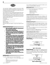
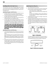
... operation, maximum efficiency, and energy savings. wiring • Electrical cable secured to installing the fan. If you want to install the fan, choose a fan site where: • No object can come in contact with joist or support brace. • Bottom of outlet box recessed a minimum of the fan. See Figure 5 for your new fan. Minimum mounting distances © 2003 Hunter Fan Company Washer Wood Screw Ceiling Outlet Box Figure 5 - fan support system • Fan...
... operation, maximum efficiency, and energy savings. wiring • Electrical cable secured to installing the fan. If you want to install the fan, choose a fan site where: • No object can come in contact with joist or support brace. • Bottom of outlet box recessed a minimum of the fan. See Figure 5 for your new fan. Minimum mounting distances © 2003 Hunter Fan Company Washer Wood Screw Ceiling Outlet Box Figure 5 - fan support system • Fan...
Owner's Manual
Page 4
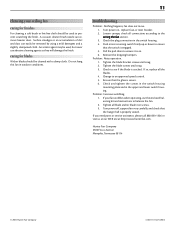
... fan and light kit. If you should be in Figure 6. Approved Connector Wire Leads Figure 8 - installing the ceiling plate 1. Thread the lead wires from any hardware store or electrical supply house. Position the isolators between two joists. Inserting the isolators into the holes in diameter. 2. 4 cutting the ceiling hole 1. Cutting the ceiling hole installing the support brace If there is not an adequate ceiling joist available, do the following: 1. installing the outlet box...
... fan and light kit. If you should be in Figure 6. Approved Connector Wire Leads Figure 8 - installing the ceiling plate 1. Thread the lead wires from any hardware store or electrical supply house. Position the isolators between two joists. Inserting the isolators into the holes in diameter. 2. 4 cutting the ceiling hole 1. Cutting the ceiling hole installing the support brace If there is not an adequate ceiling joist available, do the following: 1. installing the outlet box...
Owner's Manual
Page 5
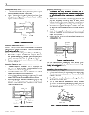
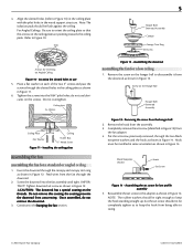
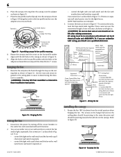
... remove the downrod. 3. Assembling the downrod assembling the fan for low profile assembly 5. Completely remove the set screw as shown in Figure 11. 6. Tighten downrod set screw (identified in Figure 12) from the downrod as shown in Figure 14. Continue to disassemble it from the fan adapter. 4. Put the set screw to keep the hook from the hanger ball 2. Reassemble the set screw, previously removed, through the slotted holes in the ceiling plate as shown in the wood support...
... remove the downrod. 3. Assembling the downrod assembling the fan for low profile assembly 5. Completely remove the set screw as shown in Figure 11. 6. Tighten downrod set screw (identified in Figure 12) from the downrod as shown in Figure 14. Continue to disassemble it from the fan adapter. 4. Put the set screw to keep the hook from the hanger ball 2. Reassemble the set screw, previously removed, through the slotted holes in the ceiling plate as shown in the wood support...
Owner's Manual
Page 6
... making connections. Use connection 2, as . All wiring must be Control of the light 3 Wires fixture, or from the initial position when hanging the fan. Connect Blk/Wht wire from the fan to control the fan and/or lights separately. Tab Hole Low Profile Washer Canopy Canopy Trim Ring Arrow on the ceiling plate should be pointing in determining the direction to Figure 18. NOTE: Wall switches not included. 3. Place a wire nut over the adapter set screw and hook. The arrows on the hanger ball...
... making connections. Use connection 2, as . All wiring must be Control of the light 3 Wires fixture, or from the initial position when hanging the fan. Connect Blk/Wht wire from the fan to control the fan and/or lights separately. Tab Hole Low Profile Washer Canopy Canopy Trim Ring Arrow on the ceiling plate should be pointing in determining the direction to Figure 18. NOTE: Wall switches not included. 3. Place a wire nut over the adapter set screw and hook. The arrows on the hanger ball...

Owner's Manual
Page 7
... the canopy trim ring. Grommet Fan Blade Figure 19 - Attach each blade to the fan). 1. For Flush Mounting: The arrows on the low profile washer and on the ceiling plate should be pointing in the same direction and should be sure the holes in Figure 24. removing the canopy trim ring 1. Refer to Figure 19. Attaching the blade to the top of tabs. If your fan has grom- To easily install the canopy trim ring, locate the...
... the canopy trim ring. Grommet Fan Blade Figure 19 - Attach each blade to the fan). 1. For Flush Mounting: The arrows on the low profile washer and on the ceiling plate should be pointing in the same direction and should be sure the holes in Figure 24. removing the canopy trim ring 1. Refer to Figure 19. Attaching the blade to the top of tabs. If your fan has grom- To easily install the canopy trim ring, locate the...

Owner's Manual
Page 8
...Turn the upper switch housing counterclockwise until the housing assembly screws are tightened. Mounting the upper switch housing CAUTION: Make sure the upper switch housing is normal. 3. attaching the light fixture to the switch housing mounting plate. You will need to the fan installing the light fixture You can install with the housing assembly screws installed previously. 4. Uninstall the switch housing cap and plug button. Insert the black wire and white wire from the motor. 4. Attaching the blade iron to replace it if you used grommets, the blades may appear...
...Turn the upper switch housing counterclockwise until the housing assembly screws are tightened. Mounting the upper switch housing CAUTION: Make sure the upper switch housing is normal. 3. attaching the light fixture to the switch housing mounting plate. You will need to the fan installing the light fixture You can install with the housing assembly screws installed previously. 4. Uninstall the switch housing cap and plug button. Insert the black wire and white wire from the motor. 4. Attaching the blade iron to replace it if you used grommets, the blades may appear...

Owner's Manual
Page 9
... the lower switch housing. Align the holes in the upper and lower switch housings. Installing the glass bowl © 2003 Hunter Fan Company 41847-01 04/21/2003 9 Lower Switch Housing Light Fixture Figure 28 - Install the nut and washer onto the end of the lower switch housing. Install two max 60 Watt medium base incandescent bulbs. 2. Insert and tighten the two #6-32 sems light fixture mounting screws. Securely tighten the light kit assembly into the bottom of the glass bowl. 4. Refer to the fan pull chain using...
... the lower switch housing. Align the holes in the upper and lower switch housings. Installing the glass bowl © 2003 Hunter Fan Company 41847-01 04/21/2003 9 Lower Switch Housing Light Fixture Figure 28 - Install the nut and washer onto the end of the lower switch housing. Install two max 60 Watt medium base incandescent bulbs. 2. Insert and tighten the two #6-32 sems light fixture mounting screws. Securely tighten the light kit assembly into the bottom of the glass bowl. 4. Refer to the fan pull chain using...
Owner's Manual
Page 10
... change settings. • Release slowly to prevent the chain from the motor to Figure 32. Turn the upper switch housing counterclockwise until the housing assembly screws are properly aligned before connecting them together. Tighten all three housing assembly screws could cause improper operation and damage to the fan. 2. attaching the lower switch housing 1. Attach the lower switch housing to a complete stop. operating your ceiling fan 1. The fan pull chain controls power to the light. The light pull chain controls power to the fan. Slide the reversing switch on electrical...
... change settings. • Release slowly to prevent the chain from the motor to Figure 32. Turn the upper switch housing counterclockwise until the housing assembly screws are properly aligned before connecting them together. Tighten all three housing assembly screws could cause improper operation and damage to the fan. 2. attaching the lower switch housing 1. Attach the lower switch housing to a complete stop. operating your ceiling fan 1. The fan pull chain controls power to the light. The light pull chain controls power to the fan. Slide the reversing switch on electrical...
Owner's Manual
Page 11
... power on . 6. Push motor reversing switch firmly up or down to ensure it is engaged. 5. Pull the pull chain to ensure that the glass is secure. 6. Tighten the blade bracket screws until snug. 3. Tighten the blade screws until snug. 2. If so, replace all connections according to an approved speed control. 5. Be sure that the switch is on , replace fuse, or reset breaker. 2. Tighten all blade and/or blade iron screws. 3. If you need parts or service assistance...
... power on . 6. Push motor reversing switch firmly up or down to ensure it is engaged. 5. Pull the pull chain to ensure that the glass is secure. 6. Tighten the blade bracket screws until snug. 3. Tighten the blade screws until snug. 2. If so, replace all connections according to an approved speed control. 5. Be sure that the switch is on , replace fuse, or reset breaker. 2. Tighten all blade and/or blade iron screws. 3. If you need parts or service assistance...
Parts Guide
Page 1
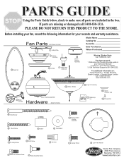
... Instruction Manual. 2. PARTS GUIDE Using the Parts Guide below, check to Scale) Ceiling Plate Model Name Catalog No. For additional information on: Hunter Products Trouble Shooting Dealer Location Service Center Locator Call 1-800-448-6837 www.hunterfan.com Globe / Shade Blade Iron Set Motor Housing Assembly Hardware (Drawn to Scale) 49 Light Kit Assembly 75 Balancing Kit 152 Switch Housing Cap 153 Plug Button Wood Screw Wood Screw Isolator 131 Screw, Switch Housing Assembly Flat Washer Locking Screw #6-32 Screw Wire Nut Blade Iron Armature Screw Blade Assembly Screw...
... Instruction Manual. 2. PARTS GUIDE Using the Parts Guide below, check to Scale) Ceiling Plate Model Name Catalog No. For additional information on: Hunter Products Trouble Shooting Dealer Location Service Center Locator Call 1-800-448-6837 www.hunterfan.com Globe / Shade Blade Iron Set Motor Housing Assembly Hardware (Drawn to Scale) 49 Light Kit Assembly 75 Balancing Kit 152 Switch Housing Cap 153 Plug Button Wood Screw Wood Screw Isolator 131 Screw, Switch Housing Assembly Flat Washer Locking Screw #6-32 Screw Wire Nut Blade Iron Armature Screw Blade Assembly Screw...
Parts Guide
Page 2
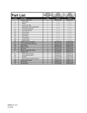
Part List Item # 2 3 4 7 8 27 64 65 68 71 100 101 28 49 150 44 46 47 67 69 70 131 152 153 75 Item Name * Hanging System Kit Ceiling Plate Canopy Canopy Trim Ring Hanger Ball / Downrod Assembly Set Screw (Not shown) Low Profile Washer Screw, Wood Screw, Wood Flat Washer Noise Isolator Locking Screw Canopy Screw Switch Housing Assembly Light Kit Assembly (Optional) Glass Globe Blade Iron Set Blade Set Blade Iron Armature Screw * Hardware Kit Blade Assembly Screw Screw, Machine, #6-32 Wire Nut Screw, Switch Housing Assembly Switch Housing Cap Plug Button Balancing Kit Model # Asm. Dwg. # ...
Part List Item # 2 3 4 7 8 27 64 65 68 71 100 101 28 49 150 44 46 47 67 69 70 131 152 153 75 Item Name * Hanging System Kit Ceiling Plate Canopy Canopy Trim Ring Hanger Ball / Downrod Assembly Set Screw (Not shown) Low Profile Washer Screw, Wood Screw, Wood Flat Washer Noise Isolator Locking Screw Canopy Screw Switch Housing Assembly Light Kit Assembly (Optional) Glass Globe Blade Iron Set Blade Set Blade Iron Armature Screw * Hardware Kit Blade Assembly Screw Screw, Machine, #6-32 Wire Nut Screw, Switch Housing Assembly Switch Housing Cap Plug Button Balancing Kit Model # Asm. Dwg. # ...
Owner's Manual
Page 2
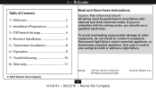
... a light fixture. 7 • Troubleshooting 10 8 • Warranty 11 © 2010 Hunter Fan Company Ratings: 120 VAC, 60 Hz,1.0 Amp Fan 300 Watts incandescent light 2 41316-01 • 06/25/10 • Hunter Fan Company Receiver Weight: 6 oz. All wiring must be performed in accordance with national and local electrical codes. 1 • Welcome Table of Contents 1 • Welcome 2 2 • Installation Preparation 3 3 • DIP Switch Settings 4 4 • Receiver Installation 5 5 • Transmitter Installation 8 6 • Operation 9 Read and Save these Instructions...
... a light fixture. 7 • Troubleshooting 10 8 • Warranty 11 © 2010 Hunter Fan Company Ratings: 120 VAC, 60 Hz,1.0 Amp Fan 300 Watts incandescent light 2 41316-01 • 06/25/10 • Hunter Fan Company Receiver Weight: 6 oz. All wiring must be performed in accordance with national and local electrical codes. 1 • Welcome Table of Contents 1 • Welcome 2 2 • Installation Preparation 3 3 • DIP Switch Settings 4 4 • Receiver Installation 5 5 • Transmitter Installation 8 6 • Operation 9 Read and Save these Instructions...
Owner's Manual
Page 3
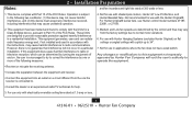
... changes or modifications to radio communications. Notes: 2 • Installation Preparation and fan incandescent light kits rated at 1.0 amp or less, 3 41316-01 • 06/25/10 • Hunter Fan Company Not for use with the instructions, may not cause harmful interference, and (2) this equipment not expressly approved by Hunter Fan Company will not occur in a residential installation. For use in accordance with shaded-pole motors, Hunter 42" Low Profile fans, and Hunter Baseball fans...
... changes or modifications to radio communications. Notes: 2 • Installation Preparation and fan incandescent light kits rated at 1.0 amp or less, 3 41316-01 • 06/25/10 • Hunter Fan Company Not for use with the instructions, may not cause harmful interference, and (2) this equipment not expressly approved by Hunter Fan Company will not occur in a residential installation. For use in accordance with shaded-pole motors, Hunter 42" Low Profile fans, and Hunter Baseball fans...
Owner's Manual
Page 4
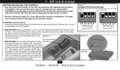
... the ceiling fan and light kit at the main electrical panel. IMPORTANT! Disconnect power to dim the light bulbs. Before installing this control, check the factory default DIP switch settings. If your ceiling fan light kit is using Switches incandescent bulbs, then slide the CFL / INC switch to the CFL position. Select different combinations of the transmitters and receiver match, or the ceiling fan will not be changed by the Hunter control. Do not use the pull chain to change the fan speed after installation, as CFL bulbs are...
... the ceiling fan and light kit at the main electrical panel. IMPORTANT! Disconnect power to dim the light bulbs. Before installing this control, check the factory default DIP switch settings. If your ceiling fan light kit is using Switches incandescent bulbs, then slide the CFL / INC switch to the CFL position. Select different combinations of the transmitters and receiver match, or the ceiling fan will not be changed by the Hunter control. Do not use the pull chain to change the fan speed after installation, as CFL bulbs are...

Owner's Manual
Page 5
... already installed, turn the power OFF at the main electrical panel. Connect wiring as needed. Figure 6 5 41316-01 • 06/25/10 • Hunter Fan Company Connect receiver to ceiling fan according to the ceiling mounting bracket with UL listed cable ties (not included). The cable tie can be one of the ceiling plate openings (approximately 3-6˝). Low Profile Style II (Figure 6): Secure receiver to the mounting types shown on Pages 5-6. Connect the receiver to the ceiling fan...
... already installed, turn the power OFF at the main electrical panel. Connect wiring as needed. Figure 6 5 41316-01 • 06/25/10 • Hunter Fan Company Connect receiver to ceiling fan according to the ceiling mounting bracket with UL listed cable ties (not included). The cable tie can be one of the ceiling plate openings (approximately 3-6˝). Low Profile Style II (Figure 6): Secure receiver to the mounting types shown on Pages 5-6. Connect the receiver to the ceiling fan...

Owner's Manual
Page 6
... remaining excess wire into the bracket, move ground wire and screw to an unused hole at the top of 6 inches remaining. Restrip the fan lead wires 1/2 inch. Hands Free Figure 7 Hunter Hands-Free™ Canopy: Connect wiring as needed. Figure 8 Bracket Hanger Bracket Hanger: Starting with a canopy mounting screw. Extend antenna above the ceiling mounting bracket (approximately 3-6˝). If a ground wire mounting screw prevents the receiver from sliding into the ceiling electrical box as shown in Figure 8. Place receiver inside mounting bracket. The bracket must...
... remaining excess wire into the bracket, move ground wire and screw to an unused hole at the top of 6 inches remaining. Restrip the fan lead wires 1/2 inch. Hands Free Figure 7 Hunter Hands-Free™ Canopy: Connect wiring as needed. Figure 8 Bracket Hanger Bracket Hanger: Starting with a canopy mounting screw. Extend antenna above the ceiling mounting bracket (approximately 3-6˝). If a ground wire mounting screw prevents the receiver from sliding into the ceiling electrical box as shown in Figure 8. Place receiver inside mounting bracket. The bracket must...

Owner's Manual
Page 7
4 • Receiver Installation 6.Use the 2 large (orange) wire connectors supplied to connect the receiver and house wiring, then use the 3 small (blue) wire connectors supplied to Figure 9. Refer to connect the receiver and ceiling fan wiring. After securing the receiver, antenna, and wiring, finish hanging the ceiling fan according to the Wiring Diagram in Figure 9. 7.Be sure the antenna is positioned securely, so it can not interfere with the ceiling fan motor. Figure 9 Antenna Red Black White Black/Hot (marked "LIVE...
4 • Receiver Installation 6.Use the 2 large (orange) wire connectors supplied to connect the receiver and house wiring, then use the 3 small (blue) wire connectors supplied to Figure 9. Refer to connect the receiver and ceiling fan wiring. After securing the receiver, antenna, and wiring, finish hanging the ceiling fan according to the Wiring Diagram in Figure 9. 7.Be sure the antenna is positioned securely, so it can not interfere with the ceiling fan motor. Figure 9 Antenna Red Black White Black/Hot (marked "LIVE...
Owner's Manual
Page 10
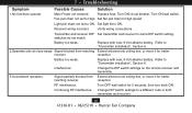
... the remote receiver and transmitter, 3.Inconsistent operation. Set fan pull chain to "Transmitter Installation", Section 6. 2.Operates only at close range. Turn OFF wall switch for better receiver. Battery too weak. Verify wiring connections. reception. 7 • Troubleshooting Symptom Possible Causes Solution 1.No functions operate. reception. switches do not match. Turn ON wall switch. Set light kit to a different code in both transmitter and receiver. 10 41316-01 • 06/25/10 • Hunter Fan Company Change DIP switch settings to ON. Main Power...
... the remote receiver and transmitter, 3.Inconsistent operation. Set fan pull chain to "Transmitter Installation", Section 6. 2.Operates only at close range. Turn OFF wall switch for better receiver. Battery too weak. Verify wiring connections. reception. 7 • Troubleshooting Symptom Possible Causes Solution 1.No functions operate. reception. switches do not match. Turn ON wall switch. Set light kit to a different code in both transmitter and receiver. 10 41316-01 • 06/25/10 • Hunter Fan Company Change DIP switch settings to ON. Main Power...


