Installation Instructions
Page 1
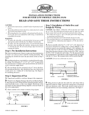
... CEILING OUTLET BOX #8 WOODSCREW & WASHER (2) REQUIRED FIGURE 2 B. Make certain that your fan is securely mounted to 2 x 4 cross brace between rotating fan blades. INSTALLATION INSTRUCTIONS FOR HUNTER LOW PROFILE CEILING FANS READ AND SAVE THESE INSTRUCTIONS CAUTION: 1. To avoid possible electrical shock, be certain it contains... a bag of Outlet Box and Rough-In Wiring CAUTION: Your Hunter ceiling fan with national and local elec- If you are aligned with this fan. Unpack unit carefully to avoid any hardware store or electrical supply house. The ...
... CEILING OUTLET BOX #8 WOODSCREW & WASHER (2) REQUIRED FIGURE 2 B. Make certain that your fan is securely mounted to 2 x 4 cross brace between rotating fan blades. INSTALLATION INSTRUCTIONS FOR HUNTER LOW PROFILE CEILING FANS READ AND SAVE THESE INSTRUCTIONS CAUTION: 1. To avoid possible electrical shock, be certain it contains... a bag of Outlet Box and Rough-In Wiring CAUTION: Your Hunter ceiling fan with national and local elec- If you are aligned with this fan. Unpack unit carefully to avoid any hardware store or electrical supply house. The ...
Installation Instructions
Page 2
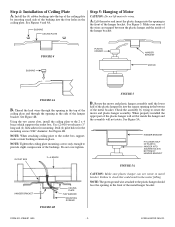
... WASHER MOUNTING SCREWS CAUTION: Make sure plastic hanger can not rotate in the side of the metal bracket. FORM NO. 41068-01 8/95 - 2 - ©1995 HUNTER FAN CO. See Figures 4 and 4A. Use (2) #10 woodscrews 3" long and (2) flatwashers for the mounting screws 9/64" diameter. FIGURE 4 BUSHING PLASTIC HANGER HANGER BRACKET MOTOR FIGURE...
... WASHER MOUNTING SCREWS CAUTION: Make sure plastic hanger can not rotate in the side of the metal bracket. FORM NO. 41068-01 8/95 - 2 - ©1995 HUNTER FAN CO. See Figures 4 and 4A. Use (2) #10 woodscrews 3" long and (2) flatwashers for the mounting screws 9/64" diameter. FIGURE 4 BUSHING PLASTIC HANGER HANGER BRACKET MOTOR FIGURE...

Installation Instructions
Page 3
... correct alignment of the housing. Do not tighten until screw mates with the accessory. FORM NO. 41068-01 8/95 - 3 - ©1995 HUNTER FAN CO. NOTE: If a separate wall switch will be acceptable for use the screws to attach the blades to the wall switch lead, following wiring ...the white electrical supply lead to the blade bracket. NOTE: If the wires are not pushed up into the bracket and tightened. Step 7: Finish Fan Assembly A. B. NOTE: Grommets are assembled. B. Using two 8-32 by approximately 5/8" long screws, from twisting when the blades are usually assembled ...
... correct alignment of the housing. Do not tighten until screw mates with the accessory. FORM NO. 41068-01 8/95 - 3 - ©1995 HUNTER FAN CO. NOTE: If a separate wall switch will be acceptable for use the screws to attach the blades to the wall switch lead, following wiring ...the white electrical supply lead to the blade bracket. NOTE: If the wires are not pushed up into the bracket and tightened. Step 7: Finish Fan Assembly A. B. NOTE: Grommets are assembled. B. Using two 8-32 by approximately 5/8" long screws, from twisting when the blades are usually assembled ...
Installation Instructions
Page 4
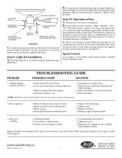
... power off and allow to approved speed control. 3. If you wish to change direction, switch fan off while checking). 3. fan does not move.* 1. Motor reversing switch not engaged. 4. Pull switch chain. *NOTE: If blades will disappear. ©1995 HUNTER FAN CO. Blade cracked. 4. Tighten screws until snug. 2. Change to stop. Unbalanced blades. 2. Loose blades...
... power off and allow to approved speed control. 3. If you wish to change direction, switch fan off while checking). 3. fan does not move.* 1. Motor reversing switch not engaged. 4. Pull switch chain. *NOTE: If blades will disappear. ©1995 HUNTER FAN CO. Blade cracked. 4. Tighten screws until snug. 2. Change to stop. Unbalanced blades. 2. Loose blades...


