Installation Instructions
Page 1
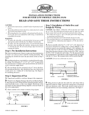
... shipped. Check for a standard drywall or plas- Step 3: Installation of parts. The outermost holes will need a 4" x 1-1/2" or 4" x 1/2" octagon outlet box and wire nuts (3) which can come in normal use a lubricant on screws. TO FLOOR FORM NO. 41068-01 8/95 FIGURE 1 24" CLEARANCE TO OBSTRUCTIONS - 1 - trical codes. Check to 35 lbs. ter ceiling. Mounting must be certain electricity is "off at the fuse panel when inspecting or repairing installation...
... shipped. Check for a standard drywall or plas- Step 3: Installation of parts. The outermost holes will need a 4" x 1-1/2" or 4" x 1/2" octagon outlet box and wire nuts (3) which can come in normal use a lubricant on screws. TO FLOOR FORM NO. 41068-01 8/95 FIGURE 1 24" CLEARANCE TO OBSTRUCTIONS - 1 - trical codes. Check to 35 lbs. ter ceiling. Mounting must be certain electricity is "off at the fuse panel when inspecting or repairing installation...
Installation Instructions
Page 2
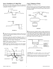
.... BUSHING CEILING PLATE Step 5: Hanging of the metal hanger bracket. Using the two center slots, install the ceiling plate to check this could result in metal bracket. OUTLET BOX 2 x 4 BRACE FIGURE 5 B. HANGER BRACKET FIT LOWER HALF OF PLASTIC HANGER INTO SQUARE HOLE IN BOTTOM OF HANGER BRACKET FIGURE 5A HANGER BRACKET FIGURE 4B CEILING PLATE FLAT WASHER MOUNTING SCREWS CAUTION: Make sure plastic hanger can not rotate in the motor falling. When properly installed the upper part of the hanger bracket. Make...
.... BUSHING CEILING PLATE Step 5: Hanging of the metal hanger bracket. Using the two center slots, install the ceiling plate to check this could result in metal bracket. OUTLET BOX 2 x 4 BRACE FIGURE 5 B. HANGER BRACKET FIT LOWER HALF OF PLASTIC HANGER INTO SQUARE HOLE IN BOTTOM OF HANGER BRACKET FIGURE 5A HANGER BRACKET FIGURE 4B CEILING PLATE FLAT WASHER MOUNTING SCREWS CAUTION: Make sure plastic hanger can not rotate in the motor falling. When properly installed the upper part of the hanger bracket. Make...

Installation Instructions
Page 3
... parts in during assembly to hold in hub by turning screw and readjusting blade bracket until both screws have been put in blade bracket. B. Use a screwdriver to assure correct alignment of the hanger bracket. Align blade holes with mounting holes in place. FORM NO. 41068-01 8/95 - 3 - ©1995 HUNTER FAN CO. Connect the ground wire to the motor. The wall switch must be driven all screws are usually assembled by approximately 5/8" long screws, from the motor, using grommets...
... parts in during assembly to hold in hub by turning screw and readjusting blade bracket until both screws have been put in blade bracket. B. Use a screwdriver to assure correct alignment of the hanger bracket. Align blade holes with mounting holes in place. FORM NO. 41068-01 8/95 - 3 - ©1995 HUNTER FAN CO. Connect the ground wire to the motor. The wall switch must be driven all screws are usually assembled by approximately 5/8" long screws, from the motor, using grommets...
Installation Instructions
Page 4
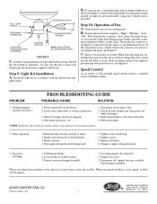
...contact your fan. Tighten screws until snug. 2. Tighten screws. 3. Fan not secure on light kit and install globe, using guide for maximum wattage printed on hanger assembly. 1. FORM NO. 41068-01 8/95 - 4 - Pull chain slowly to blades, or pull chain. C. Speed Control As an option, a wall mounted speed control switch is electrically reversible. Non-approved speed control being used. 1. Unbalanced blades. 2. Turn power off or fuse blown. 2. Nothing happens; Noisy operation. 1. Install the light kit in damage to operate. See Figure 8. Motor is available...
...contact your fan. Tighten screws until snug. 2. Tighten screws. 3. Fan not secure on light kit and install globe, using guide for maximum wattage printed on hanger assembly. 1. FORM NO. 41068-01 8/95 - 4 - Pull chain slowly to blades, or pull chain. C. Speed Control As an option, a wall mounted speed control switch is electrically reversible. Non-approved speed control being used. 1. Unbalanced blades. 2. Turn power off or fuse blown. 2. Nothing happens; Noisy operation. 1. Install the light kit in damage to operate. See Figure 8. Motor is available...


