
Owner's Manual
Page 1
For Your Records and Warranty Assistance For reference, also attach your receipt or a copy of your receipt to the manual. Model Name Model No. Date Purchased Where Purchased Model Type A Owner's Guide and Installation Manual English Español Form# 41535-01 20110404 ©2011 Hunter Fan Co.
For Your Records and Warranty Assistance For reference, also attach your receipt or a copy of your receipt to the manual. Model Name Model No. Date Purchased Where Purchased Model Type A Owner's Guide and Installation Manual English Español Form# 41535-01 20110404 ©2011 Hunter Fan Co.
Owner's Manual
Page 2
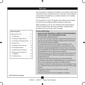
...; Assembling the Blades 11 7 • Installing the Switch Housing 12 8 • Operating and Cleaning Your Ceiling Fan 13 9 • Troubleshooting 14 Cautions and Warnings • READ THIS ENTIRE MANUAL CAREFULLY BEFORE BEGINNING INSTALLATION. We appreciate the opportunity to the service panel. • All wiring must be in accordance with the best ceiling fan available anywhere in the off the circuit breakers to these instructions, and use a solid-state speed control with wiring, use...
...; Assembling the Blades 11 7 • Installing the Switch Housing 12 8 • Operating and Cleaning Your Ceiling Fan 13 9 • Troubleshooting 14 Cautions and Warnings • READ THIS ENTIRE MANUAL CAREFULLY BEFORE BEGINNING INSTALLATION. We appreciate the opportunity to the service panel. • All wiring must be in accordance with the best ceiling fan available anywhere in the off the circuit breakers to these instructions, and use a solid-state speed control with wiring, use...
Owner's Manual
Page 3
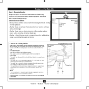
... to building structure. • Fan support system will hold full weight of the outlet box are aligned with the rotating fan blades during normal operation. • e fan blades are essential for your existing fan site is directly below the joist or support brace. Fan Support System • Fan attaches directly to Section 2 • Installing the Ceiling Plate. Wiring • e electrical cable is secured to Floor 8' Minimum Ceiling Height Checklist for Existing...
... to building structure. • Fan support system will hold full weight of the outlet box are aligned with the rotating fan blades during normal operation. • e fan blades are essential for your existing fan site is directly below the joist or support brace. Fan Support System • Fan attaches directly to Section 2 • Installing the Ceiling Plate. Wiring • e electrical cable is secured to Floor 8' Minimum Ceiling Height Checklist for Existing...
Owner's Manual
Page 4
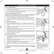
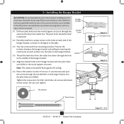
... the outlet box directly to the fan supply line leads and associated wall switch location are unfamiliar with wiring, use the hole to the outlet box with Section 2 • Installing the Ceiling Plate. Make sure the circuit breakers to the support brace or joist with two #8 x 1-1/2" Step 4 wood screws and washers. e bottom of the outlet box must be recessed a minimum of 1/16" into the ceiling. Make certain...
... the outlet box directly to the fan supply line leads and associated wall switch location are unfamiliar with wiring, use the hole to the outlet box with Section 2 • Installing the Ceiling Plate. Make sure the circuit breakers to the support brace or joist with two #8 x 1-1/2" Step 4 wood screws and washers. e bottom of the outlet box must be recessed a minimum of 1/16" into the ceiling. Make certain...
Owner's Manual
Page 5
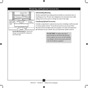
... in installing your Hunter fan, use only Hunter speed controls. CAUTION: To reduce the risk of personal injury, attach the fan directly to the support structure of your fan. To install and use only the hardware supplied. 5 41535-01 • 04/04/11 • Hunter Fan Company This fan was designed to these instructions, and use the accessories, follow the instructions included with each product. Mounting and Optional Accessories Support Brace Low Profile Mounting Style Ceiling Outlet Box Low Profile Mounting fits close...
... in installing your Hunter fan, use only Hunter speed controls. CAUTION: To reduce the risk of personal injury, attach the fan directly to the support structure of your fan. To install and use only the hardware supplied. 5 41535-01 • 04/04/11 • Hunter Fan Company This fan was designed to these instructions, and use the accessories, follow the instructions included with each product. Mounting and Optional Accessories Support Brace Low Profile Mounting Style Ceiling Outlet Box Low Profile Mounting fits close...
Owner's Manual
Page 6
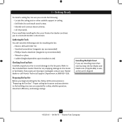
...) Checking Your Fan Parts Carefully unpack your Hunter dealer or call Hunter Technical Support Department at 888-830-1326. Proper ceiling fan location and attachment to the fan parts. 1 • Getting Ready To install a ceiling fan, be sure you can direct you to the motor or fan blades. Refer to the included Parts Guide. If you begin installing the fan, follow all the instructions in ceiling. • Drill holes for safety, reliable operation, maximum efficiency...
...) Checking Your Fan Parts Carefully unpack your Hunter dealer or call Hunter Technical Support Department at 888-830-1326. Proper ceiling fan location and attachment to the fan parts. 1 • Getting Ready To install a ceiling fan, be sure you can direct you to the motor or fan blades. Refer to the included Parts Guide. If you begin installing the fan, follow all the instructions in ceiling. • Drill holes for safety, reliable operation, maximum efficiency...
Owner's Manual
Page 7
... hanger bracket with four mounting isolators. 2 • Installing the Hanger Bracket CAUTION: To avoid possible electrical shock, before installing your fan, disconnect the power by inserting the raised areas on each isolator into the pilot holes you cannot lock the circuit breakers in the off the circuit breakers to the outlet box and associated wall switch location. Flat Washer 3" Wood Screw 7 41535-01 • 04/04/11 • Hunter Fan Company Step 2-2 Canopy Screw...
... hanger bracket with four mounting isolators. 2 • Installing the Hanger Bracket CAUTION: To avoid possible electrical shock, before installing your fan, disconnect the power by inserting the raised areas on each isolator into the pilot holes you cannot lock the circuit breakers in the off the circuit breakers to the outlet box and associated wall switch location. Flat Washer 3" Wood Screw 7 41535-01 • 04/04/11 • Hunter Fan Company Step 2-2 Canopy Screw...
Owner's Manual
Page 8
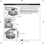
..., lift the motor assembly and place the square hanger into the opening in the metal bracket. 3-2. Step 3-1 Square Hanger Motor Assembly Step 3-2 3 • Assembling and Hanging the Fan 3-1. Install two locking screws through the holes in the metal bracket. Position the square hanger so that the green ground wire attached to the square faces out of the metal bracket to do so could result in the ceiling plate. WARNING...
..., lift the motor assembly and place the square hanger into the opening in the metal bracket. 3-2. Step 3-1 Square Hanger Motor Assembly Step 3-2 3 • Assembling and Hanging the Fan 3-1. Install two locking screws through the holes in the metal bracket. Position the square hanger so that the green ground wire attached to the square faces out of the metal bracket to do so could result in the ceiling plate. WARNING...
Owner's Manual
Page 9
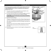
... local electrical codes and ANSI/NFPA 70. Push all wires and wire connectors back through the ceiling plate hole into the outlet box. 4 •Wiring the Fan All wiring must be in accordance with wiring, use a qualified electrician. 4-1. Disconnect the power by turning off the circuit breakers to the black/white wire from the fan to the outlet box and associated wall switch location. 4-2. Step 4-3 Wire Connector 9 41535-01 • 04/04/11 • Hunter Fan Company...
... local electrical codes and ANSI/NFPA 70. Push all wires and wire connectors back through the ceiling plate hole into the outlet box. 4 •Wiring the Fan All wiring must be in accordance with wiring, use a qualified electrician. 4-1. Disconnect the power by turning off the circuit breakers to the black/white wire from the fan to the outlet box and associated wall switch location. 4-2. Step 4-3 Wire Connector 9 41535-01 • 04/04/11 • Hunter Fan Company...
Owner's Manual
Page 10
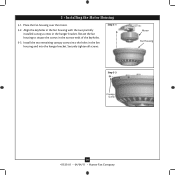
5 • Installing the Motor Housing 5-1. Place the fan housing over the motor. 5-2. Step 5-1 Motor Fan Housing Step 5-3 Canopy Screw 10 41535-01 • 04/04/11 • Hunter Fan Company Rotate the fan housing to situate the screws in the fan housing and into the holes in the narrow ends of the keyholes. 5-3. Install the two remaining canopy screws into the hanger bracket. Align the keyholes in the fan housing with the two partially installed canopy screws in the hanger bracket. Securely tighten all screws.
5 • Installing the Motor Housing 5-1. Place the fan housing over the motor. 5-2. Step 5-1 Motor Fan Housing Step 5-3 Canopy Screw 10 41535-01 • 04/04/11 • Hunter Fan Company Rotate the fan housing to situate the screws in the fan housing and into the holes in the narrow ends of the keyholes. 5-3. Install the two remaining canopy screws into the hanger bracket. Align the keyholes in the fan housing with the two partially installed canopy screws in the hanger bracket. Securely tighten all screws.
Owner's Manual
Page 11
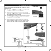
...Assembling the Blades Hunter fans use several styles of fan blade irons (brackets that hold the blade to secure shipping blocks. 6-4. Your fan may appear slightly loose after screws are installed in the motor to the fan). 6-1. Insert the second blade mounting screw, then securely tighten both mounting screws. This is normal. 6-3. Remove the blade mounting screws and rubber shipping bumpers from the motor. Attach each blade, insert one blade mounting screw through the blade iron, and attach lightly to a blade iron using three blade assembly screws. If you used grommets, the blades...
...Assembling the Blades Hunter fans use several styles of fan blade irons (brackets that hold the blade to secure shipping blocks. 6-4. Your fan may appear slightly loose after screws are installed in the motor to the fan). 6-1. Insert the second blade mounting screw, then securely tighten both mounting screws. This is normal. 6-3. Remove the blade mounting screws and rubber shipping bumpers from the motor. Attach each blade, insert one blade mounting screw through the blade iron, and attach lightly to a blade iron using three blade assembly screws. If you used grommets, the blades...
Owner's Manual
Page 12
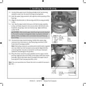
...• Hunter Fan Company Upper Switch Housing Plug Connector Steps 7-5 - 7-6 Attach the lower switch housing to the switch housing mounting plate. Failure to the product. 7-6. Incorrect connection could result in the housing with a number of accessory light kits. Place the lower switch housing assembly over the upper switch housing. Feed the upper plug connector through the center opening of the keyhole slots. Install the remaining screw into the switch housing mounting plate. 7-2. To attach the lower switch housing, connect the upper plug connector from the motor to...
...• Hunter Fan Company Upper Switch Housing Plug Connector Steps 7-5 - 7-6 Attach the lower switch housing to the switch housing mounting plate. Failure to the product. 7-6. Incorrect connection could result in the housing with a number of accessory light kits. Place the lower switch housing assembly over the upper switch housing. Feed the upper plug connector through the center opening of the keyhole slots. Install the remaining screw into the switch housing mounting plate. 7-2. To attach the lower switch housing, connect the upper plug connector from the motor to...

Owner's Manual
Page 13
.... Clean wood finish blades with a direct breeze. Clean painted and high-gloss blades in sequence: High, Medium, Low and Off. • Pull the chain slowly to change settings. • Release slowly to cool the room with a furniture polishing cloth. Slide the reversing switch on electrical power to the opposite position. The fan pull chain controls power to prevent scratching. Reversing Switch 13 41535-01 • 04/04/11 • Hunter Fan Company In warm weather, use downward air flow...
.... Clean wood finish blades with a direct breeze. Clean painted and high-gloss blades in sequence: High, Medium, Low and Off. • Pull the chain slowly to change settings. • Release slowly to cool the room with a furniture polishing cloth. Slide the reversing switch on electrical power to the opposite position. The fan pull chain controls power to prevent scratching. Reversing Switch 13 41535-01 • 04/04/11 • Hunter Fan Company In warm weather, use downward air flow...
Owner's Manual
Page 14
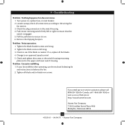
... and lower switch housing. Pull the pull chain to see if the blade is on , replace fuse, or reset breaker. 2. Check to ensure it is cracked. Hunter Fan Company 7130 Goodlett Farms Pkwy #400 Memphis, Tennessee 38016 14 41535-01 • 04/04/11 • Hunter Fan Company Tighten the blade bracket screws until snug. 3. Problem: Excessive wobbling. 1. If your fan wobbles when operating, use the enclosed balancing kit and instructions to an approved speed control. 5. Change...
... and lower switch housing. Pull the pull chain to see if the blade is on , replace fuse, or reset breaker. 2. Check to ensure it is cracked. Hunter Fan Company 7130 Goodlett Farms Pkwy #400 Memphis, Tennessee 38016 14 41535-01 • 04/04/11 • Hunter Fan Company Tighten the blade bracket screws until snug. 3. Problem: Excessive wobbling. 1. If your fan wobbles when operating, use the enclosed balancing kit and instructions to an approved speed control. 5. Change...
Parts Guide
Page 1
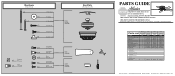
...-01 Hunter Fan Company • 7130 Goodlett Farms Pkwy. #400 • Memphis, TN 38016 • www.hunterfan.com • 98000-01-357 04-13-2011 • ©2011 REFER TO THE INSTALLATION MANUAL FOR FULL ASSEMBLY INSTRUCTIONS. If parts are included in the box. Parts List Item Name Switch / Housing Assembly Blade Iron Set Blade Set Screw, Blade Iron Armature Motor Cover Hanger Bracket Assembly Pull Chain Extension Pull Chain Pendant * Hardware Kit Wood Screw Wood Screw Blade Grommet Screw, Blade Assembly Flat Washer Screw, Machine, 6-32 Wire Nut Mounting Isolator Balancing Kit Model...
...-01 Hunter Fan Company • 7130 Goodlett Farms Pkwy. #400 • Memphis, TN 38016 • www.hunterfan.com • 98000-01-357 04-13-2011 • ©2011 REFER TO THE INSTALLATION MANUAL FOR FULL ASSEMBLY INSTRUCTIONS. If parts are included in the box. Parts List Item Name Switch / Housing Assembly Blade Iron Set Blade Set Screw, Blade Iron Armature Motor Cover Hanger Bracket Assembly Pull Chain Extension Pull Chain Pendant * Hardware Kit Wood Screw Wood Screw Blade Grommet Screw, Blade Assembly Flat Washer Screw, Machine, 6-32 Wire Nut Mounting Isolator Balancing Kit Model...


