
Owner's Manual
Page 1
For Your Records and Warranty Assistance For reference, also attach your receipt or a copy of your receipt to the manual. Model Name Model No. Date Purchased Where Purchased Model Type A Owner's Guide and Installation Manual English Español Form# 41535-01 20110404 ©2011 Hunter Fan Co.
For Your Records and Warranty Assistance For reference, also attach your receipt or a copy of your receipt to the manual. Model Name Model No. Date Purchased Where Purchased Model Type A Owner's Guide and Installation Manual English Español Form# 41535-01 20110404 ©2011 Hunter Fan Co.
Owner's Manual
Page 2
... electrical shock, before installing your fan, disconnect the power by turning off position, securely fasten a prominent warning device, such as a tag, to the outlet box and associated wall switch location. SAVE THESE INSTRUCTIONS. • Use only Hunter replacement parts. • To reduce the risk of personal injury, attach the fan directly to the support structure of the fan motor housing). If you complete instructions for your fan. Before installing your fan, for installing and operating...
... electrical shock, before installing your fan, disconnect the power by turning off position, securely fasten a prominent warning device, such as a tag, to the outlet box and associated wall switch location. SAVE THESE INSTRUCTIONS. • Use only Hunter replacement parts. • To reduce the risk of personal injury, attach the fan directly to the support structure of the fan motor housing). If you complete instructions for your fan. Before installing your fan, for installing and operating...
Owner's Manual
Page 3
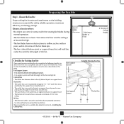
... by an approved connector. • Six inches of the fan and light kit. If you want to use an existing fan site, complete the following checklist to building structure. • Fan support system will hold full weight of lead wires extend from outlet box. Fan Support System • Fan attaches directly to determine if the site is secured to Section 2 • Installing the Ceiling Plate. Wiring • e electrical cable is...
... by an approved connector. • Six inches of the fan and light kit. If you want to use an existing fan site, complete the following checklist to building structure. • Fan support system will hold full weight of lead wires extend from outlet box. Fan Support System • Fan attaches directly to determine if the site is secured to Section 2 • Installing the Ceiling Plate. Wiring • e electrical cable is...
Owner's Manual
Page 4
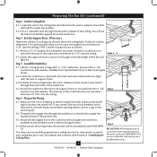
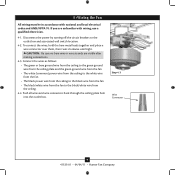
... the fan and light kit. Attach the outlet box directly to the fan supply line leads and associated wall switch location are unfamiliar with an approved connector, available at least 6" beyond the box. 5-3. For instructions to install your ceiling fan, go to the service panel. 5-2. read the fan supply line through the outlet box so that both the inner and outer holes in accordance with the joist or support...
... the fan and light kit. Attach the outlet box directly to the fan supply line leads and associated wall switch location are unfamiliar with an approved connector, available at least 6" beyond the box. 5-3. For instructions to install your ceiling fan, go to the service panel. 5-2. read the fan supply line through the outlet box so that both the inner and outer holes in accordance with the joist or support...
Owner's Manual
Page 5
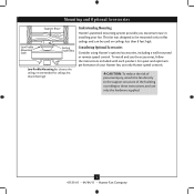
... be used on ceilings less than 8 feet high Understanding Mounting Hunter's patented mounting system provides you maximum ease in installing your Hunter fan, use only Hunter speed controls. CAUTION: To reduce the risk of personal injury, attach the fan directly to the support structure of your fan. To install and use the accessories, follow the instructions included with each product. Mounting and Optional Accessories Support Brace Low Profile Mounting Style Ceiling Outlet Box Low Profile Mounting fits close to the ceiling, recommended for ceilings less...
... be used on ceilings less than 8 feet high Understanding Mounting Hunter's patented mounting system provides you maximum ease in installing your Hunter fan, use only Hunter speed controls. CAUTION: To reduce the risk of personal injury, attach the fan directly to the support structure of your fan. To install and use the accessories, follow the instructions included with each product. Mounting and Optional Accessories Support Brace Low Profile Mounting Style Ceiling Outlet Box Low Profile Mounting fits close to the ceiling, recommended for ceilings less...
Owner's Manual
Page 6
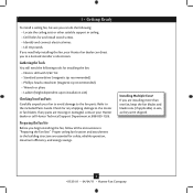
... and install wood screws. • Identify and connect electrical wires. • Lift 40 pounds. Installing Multiple Fans? Gathering the Tools You will need help installing the fan, your fan to avoid damage to the included Parts Guide. Refer to the fan parts. Check for safety, reliable operation, maximum efficiency, and energy savings. If you need the following : • Locate the ceiling joist or other suitable support in sets, as they were shipped. 6 41535...
... and install wood screws. • Identify and connect electrical wires. • Lift 40 pounds. Installing Multiple Fans? Gathering the Tools You will need help installing the fan, your fan to avoid damage to the included Parts Guide. Refer to the fan parts. Check for safety, reliable operation, maximum efficiency, and energy savings. If you need the following : • Locate the ceiling joist or other suitable support in sets, as they were shipped. 6 41535...
Owner's Manual
Page 7
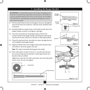
... the slotted holes in the hanger bracket with four mounting isolators. Hanger Bracket Canopy Screw 2-2. Drill two pilot holes into the holes in the hanger bracket. 2-4. Partially install two canopy screws in the holes on each end of the hanger bracket, as a tag, to the outlet box and associated wall switch location. Note: The isolators should be flush against the ceiling. 2-6. do not use lubricants on each of the hanger bracket. Tighten the screws into the pilot holes you drilled...
... the slotted holes in the hanger bracket with four mounting isolators. Hanger Bracket Canopy Screw 2-2. Drill two pilot holes into the holes in the hanger bracket. 2-4. Partially install two canopy screws in the holes on each end of the hanger bracket, as a tag, to the outlet box and associated wall switch location. Note: The isolators should be flush against the ceiling. 2-6. do not use lubricants on each of the hanger bracket. Tighten the screws into the pilot holes you drilled...
Owner's Manual
Page 8
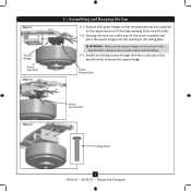
..., lift the motor assembly and place the square hanger into the opening in the ceiling plate. Green Ground Wire Step 3-3 Green Ground Wire #8-32 x 1" Screw Locking Screw 8 41535-01 • 04/04/11 • Hunter Fan Company Step 3-1 Square Hanger Motor Assembly Step 3-2 3 • Assembling and Hanging the Fan 3-1. Install two locking screws through the holes in the fan falling. 3-3. Holding the wires out of the large opening in the metal bracket. 3-2. Position the...
..., lift the motor assembly and place the square hanger into the opening in the ceiling plate. Green Ground Wire Step 3-3 Green Ground Wire #8-32 x 1" Screw Locking Screw 8 41535-01 • 04/04/11 • Hunter Fan Company Step 3-1 Square Hanger Motor Assembly Step 3-2 3 • Assembling and Hanging the Fan 3-1. Install two locking screws through the holes in the fan falling. 3-3. Holding the wires out of the large opening in the metal bracket. 3-2. Position the...
Owner's Manual
Page 9
... wire connectors back through the ceiling plate hole into the outlet box. If you are visible after making connections. 4-3. CAUTION: Be sure no bare wire or wire strands are unfamiliar with national and local electrical codes and ANSI/NFPA 70. Step 4-3 Wire Connector 9 41535-01 • 04/04/11 • Hunter Fan Company Disconnect the power by turning off the circuit breakers to the black/white wire from the ceiling. 4-4. Connect...
... wire connectors back through the ceiling plate hole into the outlet box. If you are visible after making connections. 4-3. CAUTION: Be sure no bare wire or wire strands are unfamiliar with national and local electrical codes and ANSI/NFPA 70. Step 4-3 Wire Connector 9 41535-01 • 04/04/11 • Hunter Fan Company Disconnect the power by turning off the circuit breakers to the black/white wire from the ceiling. 4-4. Connect...
Owner's Manual
Page 10
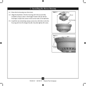
Rotate the fan housing to situate the screws in the fan housing and into the hanger bracket. Install the two remaining canopy screws into the holes in the narrow ends of the keyholes. 5-3. Place the fan housing over the motor. 5-2. Securely tighten all screws. 5 • Installing the Motor Housing 5-1. Step 5-1 Motor Fan Housing Step 5-3 Canopy Screw 10 41535-01 • 04/04/11 • Hunter Fan Company Align the keyholes in the fan housing with the two partially installed canopy screws in the hanger bracket.
Rotate the fan housing to situate the screws in the fan housing and into the hanger bracket. Install the two remaining canopy screws into the holes in the narrow ends of the keyholes. 5-3. Place the fan housing over the motor. 5-2. Securely tighten all screws. 5 • Installing the Motor Housing 5-1. Step 5-1 Motor Fan Housing Step 5-3 Canopy Screw 10 41535-01 • 04/04/11 • Hunter Fan Company Align the keyholes in the fan housing with the two partially installed canopy screws in the hanger bracket.
Owner's Manual
Page 11
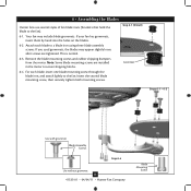
... lightly to a blade iron using three blade assembly screws. If you used grommets, the blades may include blade grommets. Note: Some blade mounting screws are tightened. Step 6-1 (Detail) Grommet Steps 6-1 - 6-2 Use with grommet Blade Assembly Screws Step 6-4 Use without grommet 11 41535-01 • 04/04/11 • Hunter Fan Company Blade Mounting Screw If your fan has grommets, insert them by hand into the holes on the blades. 6-2. For each blade to the fan. Remove the blade mounting screws and rubber shipping bumpers from the motor. 6 • Assembling the Blades Hunter fans...
... lightly to a blade iron using three blade assembly screws. If you used grommets, the blades may include blade grommets. Note: Some blade mounting screws are tightened. Step 6-1 (Detail) Grommet Steps 6-1 - 6-2 Use with grommet Blade Assembly Screws Step 6-4 Use without grommet 11 41535-01 • 04/04/11 • Hunter Fan Company Blade Mounting Screw If your fan has grommets, insert them by hand into the holes on the blades. 6-2. For each blade to the fan. Remove the blade mounting screws and rubber shipping bumpers from the motor. 6 • Assembling the Blades Hunter fans...
Owner's Manual
Page 12
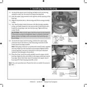
... and lower switch housings. Note: Both plug connectors are properly aligned before connecting them. Attach the lower switch housing to the switch housing mounting plate. Align the side screw holes in the lower switch housing assembly. Failure to properly attach and tighten all three screws firmly. To attach the lower switch housing, connect the upper plug connector from the motor to the product. 7-6. Steps 7-1 - 7-4 Housing Assembly Screw Lower Switch Housing Housing Assembly Screw 12 41535-01 • 04/04/11 • Hunter Fan Company Upper Switch Housing Plug...
... and lower switch housings. Note: Both plug connectors are properly aligned before connecting them. Attach the lower switch housing to the switch housing mounting plate. Align the side screw holes in the lower switch housing assembly. Failure to properly attach and tighten all three screws firmly. To attach the lower switch housing, connect the upper plug connector from the motor to the product. 7-6. Steps 7-1 - 7-4 Housing Assembly Screw Lower Switch Housing Housing Assembly Screw 12 41535-01 • 04/04/11 • Hunter Fan Company Upper Switch Housing Plug...

Owner's Manual
Page 13
... chain uses a breakaway connector that separates if the chain is jerked. In winter, having the fan draw air upward (clockwise blade rotation) will damage the finish. 8-5. In warm weather, use downward air flow pattern In cold weather, use upward air flow pattern To Change Airflow Direction Turn the fan off and let it come to the fan. 8 • Operating and Cleaning Your Ceiling Fan 8-1. Ceiling fans work best by blowing air downward (counterclockwise blade rotation...
... chain uses a breakaway connector that separates if the chain is jerked. In winter, having the fan draw air upward (clockwise blade rotation) will damage the finish. 8-5. In warm weather, use downward air flow pattern In cold weather, use upward air flow pattern To Change Airflow Direction Turn the fan off and let it come to the fan. 8 • Operating and Cleaning Your Ceiling Fan 8-1. Ceiling fans work best by blowing air downward (counterclockwise blade rotation...
Owner's Manual
Page 14
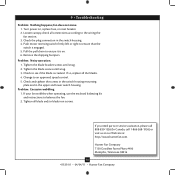
.... Turn power on . 6. Check the plug connection in the upper and lower switch housing. Push motor reversing switch firmly left or right to an approved speed control. 5. Remove the shipping bumpers. Problem: Excessive wobbling. 1. Tighten all connections according to balance the fan. 2. Loosen canopy, check all blade and/or blade iron screws. Change to ensure that the switch is engaged. 5. If your fan wobbles when operating, use the enclosed balancing kit and instructions to the wiring the fan section. 3. Hunter Fan Company 7130 Goodlett...
.... Turn power on . 6. Check the plug connection in the upper and lower switch housing. Push motor reversing switch firmly left or right to an approved speed control. 5. Remove the shipping bumpers. Problem: Excessive wobbling. 1. Tighten all connections according to balance the fan. 2. Loosen canopy, check all blade and/or blade iron screws. Change to ensure that the switch is engaged. 5. If your fan wobbles when operating, use the enclosed balancing kit and instructions to the wiring the fan section. 3. Hunter Fan Company 7130 Goodlett...
Parts Guide
Page 1
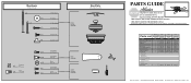
REFER TO THE INSTALLATION MANUAL FOR FULL ASSEMBLY INSTRUCTIONS. Parts List Item Name Switch / Housing Assembly Blade Iron Set Blade Set Screw, Blade Iron Armature Motor Cover Hanger Bracket Assembly Pull Chain Extension Pull Chain Pendant * Hardware Kit Wood Screw Wood Screw Blade Grommet Screw, Blade Assembly Flat Washer Screw, Machine, 6-32 Wire Nut Mounting Isolator Balancing Kit Model # Asm. THIS PARTS GUIDE IS FOR REFERENCE ONLY. Dwg. # Finish Qnty 1 1 1 11 1 1 1 1 1 1 20806 94314-02 Bright Brass Part # G1669-01 99631-05 G0677-06 63755-05 92511-03 73846-01 63756-42 G0090-01 ...
REFER TO THE INSTALLATION MANUAL FOR FULL ASSEMBLY INSTRUCTIONS. Parts List Item Name Switch / Housing Assembly Blade Iron Set Blade Set Screw, Blade Iron Armature Motor Cover Hanger Bracket Assembly Pull Chain Extension Pull Chain Pendant * Hardware Kit Wood Screw Wood Screw Blade Grommet Screw, Blade Assembly Flat Washer Screw, Machine, 6-32 Wire Nut Mounting Isolator Balancing Kit Model # Asm. THIS PARTS GUIDE IS FOR REFERENCE ONLY. Dwg. # Finish Qnty 1 1 1 11 1 1 1 1 1 1 20806 94314-02 Bright Brass Part # G1669-01 99631-05 G0677-06 63755-05 92511-03 73846-01 63756-42 G0090-01 ...


