
Installation Guide
Page 1
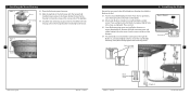
... is a ceiling joist directly above the floor and the ceiling is secured to the joist or support brace by an approved connector. For instructions to install your ceiling fan, go to your fan manual and continue with an approved connector, available at least 8 feet high. • e fan blades have now successfully prepared your new Hunter fan. o e outlet box is at any hardware store or electrical supply house. 4-2. Cut a 4" diameter hole through...
... is a ceiling joist directly above the floor and the ceiling is secured to the joist or support brace by an approved connector. For instructions to install your ceiling fan, go to your fan manual and continue with an approved connector, available at least 8 feet high. • e fan blades have now successfully prepared your new Hunter fan. o e outlet box is at any hardware store or electrical supply house. 4-2. Cut a 4" diameter hole through...

Owner's Manual
Page 1
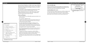
For Your Records and Warranty Assistance Model Name Catalog/Model No Serial No Date Purchased Where Purchased For reference also attach your receipt or a copy of your receipt to the manual. 42819-01 • 11/14/06
For Your Records and Warranty Assistance Model Name Catalog/Model No Serial No Date Purchased Where Purchased For reference also attach your receipt or a copy of your receipt to the manual. 42819-01 • 11/14/06
Owner's Manual
Page 2
... to these instructions. • Use only Hunter replacement parts. • To reduce the risk of personal injury, attach the fan directly to the support structure of Contents 1 • Getting Ready 4 2 • Installing the Hanger Bracket 5 3 • Assembling and Hanging the Fan..........6 4 • Wiring the Fan 7 5 • Installing the Motor Housing 8 6 • Assembling the Blades 9 7 • Completing Your Installation With or Without a Light Fixture 10 8 • Operating and Cleaning Your Ceiling Fan 14 9 • Troubleshooting 15 Your new Hunter® ceiling fan is...
... to these instructions. • Use only Hunter replacement parts. • To reduce the risk of personal injury, attach the fan directly to the support structure of Contents 1 • Getting Ready 4 2 • Installing the Hanger Bracket 5 3 • Assembling and Hanging the Fan..........6 4 • Wiring the Fan 7 5 • Installing the Motor Housing 8 6 • Assembling the Blades 9 7 • Completing Your Installation With or Without a Light Fixture 10 8 • Operating and Cleaning Your Ceiling Fan 14 9 • Troubleshooting 15 Your new Hunter® ceiling fan is...
Owner's Manual
Page 3
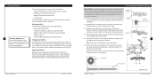
... Hunter Technical Support Department at washer on each end of the hanger bracket. Align the slotted holes in the hanger bracket. 2-4. Tighten the screws into the holes in the hanger bracket with four mounting isolators. Step 2-2 Canopy Screw Step 2-3 5 Flat Washer 3" Wood Screw 42819-01 • 11/14/06 Steps 2-4 - 2-6 Hunter Fan Company Gathering the Tools You will need help installing the fan, your fan to avoid damage to the outlet box and associated wall switch location. Drill two pilot holes...
... Hunter Technical Support Department at washer on each end of the hanger bracket. Align the slotted holes in the hanger bracket. 2-4. Tighten the screws into the holes in the hanger bracket with four mounting isolators. Step 2-2 Canopy Screw Step 2-3 5 Flat Washer 3" Wood Screw 42819-01 • 11/14/06 Steps 2-4 - 2-6 Hunter Fan Company Gathering the Tools You will need help installing the fan, your fan to avoid damage to the outlet box and associated wall switch location. Drill two pilot holes...
Owner's Manual
Page 4
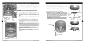
... hanger can not rotate in the ceiling plate. Motor Assembly Step 3-2 Green Ground Wire 6 Green Ground Wire Step 3-3 #8-32 x 1" Screw Locking Screw Hunter Fan Company 42819-01 • 11/14/06 All wiring must be in the metal bracket. 3-2. To connect the wires, hold the bare metal leads together and place a wire nut over them carefully back through the holes in the side of the outlet box. 4 •Wiring the Fan...
... hanger can not rotate in the ceiling plate. Motor Assembly Step 3-2 Green Ground Wire 6 Green Ground Wire Step 3-3 #8-32 x 1" Screw Locking Screw Hunter Fan Company 42819-01 • 11/14/06 All wiring must be in the metal bracket. 3-2. To connect the wires, hold the bare metal leads together and place a wire nut over them carefully back through the holes in the side of the outlet box. 4 •Wiring the Fan...
Owner's Manual
Page 5
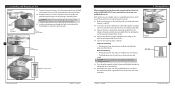
... blade to the fan. Use with the two partially installed canopy screws in the narrow ends of fan blade irons (brackets that hold the blade to the fan). 6-1. Rotate the fan housing to secure shipping blocks. Attach each blade, insert one blade mounting screw through the blade iron, and attach lightly to a blade iron using three blade assembly screws. Place the fan housing over the motor. 5-2. Securely tighten all screws. Insert the second blade mounting screw, then securely tighten both mounting screws. Remove the blade mounting screws and rubber bumpers from the motor. Your fan...
... blade to the fan. Use with the two partially installed canopy screws in the narrow ends of fan blade irons (brackets that hold the blade to the fan). 6-1. Rotate the fan housing to secure shipping blocks. Attach each blade, insert one blade mounting screw through the blade iron, and attach lightly to a blade iron using three blade assembly screws. Place the fan housing over the motor. 5-2. Securely tighten all screws. Insert the second blade mounting screw, then securely tighten both mounting screws. Remove the blade mounting screws and rubber bumpers from the motor. Your fan...
Owner's Manual
Page 6
... of installing the fan with the housing assemInbslytallation With or white wire from the lower switch housing. Light Fixture Mounting Screw Step 7-4 Hunter Fan Company 42819-01 • 11/14/06 42819-01 • 11/14/06 Step Title witch using 11 Step 7-7 Hunter Fan Company Securely tighten the nut and washer onto WARNING: Use only the light fixture supplied with an integrated light fixture assembly and an optional switch housing cap and plug button...
... of installing the fan with the housing assemInbslytallation With or white wire from the lower switch housing. Light Fixture Mounting Screw Step 7-4 Hunter Fan Company 42819-01 • 11/14/06 42819-01 • 11/14/06 Step Title witch using 11 Step 7-7 Hunter Fan Company Securely tighten the nut and washer onto WARNING: Use only the light fixture supplied with an integrated light fixture assembly and an optional switch housing cap and plug button...

Owner's Manual
Page 7
... switch housing, connect the upper plug connector from the motor to the lower plug connector in sequence: High, Medium, Low and Off. • Pull the chain slowly to change settings. • Release slowly to prevent the chain from recoiling into the blades. • The chain uses a breakaway connector that separates if the chain is complete. Note: Both plug connectors are properly aligned before inserting the globe, then retighten securely. Steps 7-6 - 7-7 Lower Switch Housing Plug Connector Detail Housing Assembly Screw Plug Connector CFL bulb (max 19W) Hunter Fan Company...
... switch housing, connect the upper plug connector from the motor to the lower plug connector in sequence: High, Medium, Low and Off. • Pull the chain slowly to change settings. • Release slowly to prevent the chain from recoiling into the blades. • The chain uses a breakaway connector that separates if the chain is complete. Note: Both plug connectors are properly aligned before inserting the globe, then retighten securely. Steps 7-6 - 7-7 Lower Switch Housing Plug Connector Detail Housing Assembly Screw Plug Connector CFL bulb (max 19W) Hunter Fan Company...
Owner's Manual
Page 8
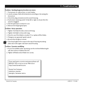
... the fan. 2. Remove the shipping bumpers. If you need parts or service assistance, please call 888-830-1326 or visit us at our Web site at http://www.hunterfan.com. Push motor reversing switch firmly left or right to ensure it is secure. 6. Tighten the blade bracket screws until snug. 3. Check to an approved speed control. 5. fan does not move. 1. Turn power on . 6. If your fan wobbles when operating, use...
... the fan. 2. Remove the shipping bumpers. If you need parts or service assistance, please call 888-830-1326 or visit us at our Web site at http://www.hunterfan.com. Push motor reversing switch firmly left or right to ensure it is secure. 6. Tighten the blade bracket screws until snug. 3. Check to an approved speed control. 5. fan does not move. 1. Turn power on . 6. If your fan wobbles when operating, use...
Parts Guide
Page 1
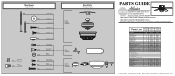
..., call 888-830-1326 for assistance. Parts List Item Name Ceiling Plate Mounting Isolator Canopy Screw Locking Screw Wood Screw 1.5" Wood Screw 3" Flat Washer Motor Cover Switch Housing Assembly Light Kit Assembly Blade Iron Set Blade Set Screw, Blade Iron Armature Hardware Kit Blade Grommet Blade Assembly Screw Screw, Machine, 6-32 Wire Connector Screw, Switch Housing Assembly Balancing Kit Cap, Switch Housing Plug Button Thumbscrew Light bulb / Bulb Globe/Shade Model # 20810 20801 Asm. REFER TO THE INSTALLATION MANUAL FOR FULL ASSEMBLY INSTRUCTIONS. Dwg. # 97419-01 97419-02 Finish...
..., call 888-830-1326 for assistance. Parts List Item Name Ceiling Plate Mounting Isolator Canopy Screw Locking Screw Wood Screw 1.5" Wood Screw 3" Flat Washer Motor Cover Switch Housing Assembly Light Kit Assembly Blade Iron Set Blade Set Screw, Blade Iron Armature Hardware Kit Blade Grommet Blade Assembly Screw Screw, Machine, 6-32 Wire Connector Screw, Switch Housing Assembly Balancing Kit Cap, Switch Housing Plug Button Thumbscrew Light bulb / Bulb Globe/Shade Model # 20810 20801 Asm. REFER TO THE INSTALLATION MANUAL FOR FULL ASSEMBLY INSTRUCTIONS. Dwg. # 97419-01 97419-02 Finish...


