
Installation Guide
Page 1
... box directly to the fan supply line leads and associated wall switch location are aligned with 2 • Installing the Ceiling Plate. CAUTION: All wiring must be in contact with the rotating fan blades during normal operation. • e fan blades are unfamiliar with the joist or support brace. 4-3. o e bottom of 1/16" into the ceiling. If your ceiling fan site. o e outer holes of the fan and light kit. If you want to use...
... box directly to the fan supply line leads and associated wall switch location are aligned with 2 • Installing the Ceiling Plate. CAUTION: All wiring must be in contact with the rotating fan blades during normal operation. • e fan blades are unfamiliar with the joist or support brace. 4-3. o e bottom of 1/16" into the ceiling. If your ceiling fan site. o e outer holes of the fan and light kit. If you want to use...

Owner's Manual
Page 1
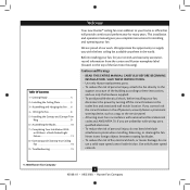
Date Purchased Where Purchased Type 2 Models Owner's Guide and Installation Manual English Español Form# 42508-01 20080923 ©2008 Hunter Fan Co. Model Name Model No. Catalog No. For Your Records and Warranty Assistance For reference, also attach your receipt or a copy of your receipt to the manual.
Date Purchased Where Purchased Type 2 Models Owner's Guide and Installation Manual English Español Form# 42508-01 20080923 ©2008 Hunter Fan Co. Model Name Model No. Catalog No. For Your Records and Warranty Assistance For reference, also attach your receipt or a copy of your receipt to the manual.
Owner's Manual
Page 2
... the outlet box and associated wall switch location. Use only Hunter speed controls. © 2008 Hunter Fan Company 2 42508-01 • 09/23/08 • Hunter Fan Company SAVE THESE INSTRUCTIONS. • Use only Hunter replacement parts. • To reduce the risk of personal injury, attach the fan directly to the support structure of the fan motor housing). Before installing your fan, for many years. We appreciate the opportunity to supply you complete instructions for installing and operating your home or...
... the outlet box and associated wall switch location. Use only Hunter speed controls. © 2008 Hunter Fan Company 2 42508-01 • 09/23/08 • Hunter Fan Company SAVE THESE INSTRUCTIONS. • Use only Hunter replacement parts. • To reduce the risk of personal injury, attach the fan directly to the support structure of the fan motor housing). Before installing your fan, for many years. We appreciate the opportunity to supply you complete instructions for installing and operating your home or...
Owner's Manual
Page 3
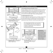
Considering Optional Accessories Consider using Hunter's optional accessories, including a wall-mounted or remote speed control. To install and use only Hunter speed controls. For quiet and optimum performance of your Hunter fan, use the accessories, follow the instructions included with each product. All Hunter fans use only the hardware supplied. 3 42508-01 • 09/23/08 • Hunter Fan Company You can purchase Hunter extension downrods. The steps in one of the building according to these instructions, and use sturdy 3/4" diameter pipe...
Considering Optional Accessories Consider using Hunter's optional accessories, including a wall-mounted or remote speed control. To install and use only Hunter speed controls. For quiet and optimum performance of your Hunter fan, use the accessories, follow the instructions included with each product. All Hunter fans use only the hardware supplied. 3 42508-01 • 09/23/08 • Hunter Fan Company You can purchase Hunter extension downrods. The steps in one of the building according to these instructions, and use sturdy 3/4" diameter pipe...
Owner's Manual
Page 4
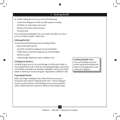
... tools for and install wood screws. • Identify and connect electrical wires. • Lift 40 pounds. Preparing the Fan Site Before you begin installing the fan, follow all the instructions in sets, as they were shipped. 4 42508-01 • 09/23/08 • Hunter Fan Company If you need the following : • Locate the ceiling joist or other suitable support in ceiling. • Drill holes for installing the fan: • Electric drill with...
... tools for and install wood screws. • Identify and connect electrical wires. • Lift 40 pounds. Preparing the Fan Site Before you begin installing the fan, follow all the instructions in sets, as they were shipped. 4 42508-01 • 09/23/08 • Hunter Fan Company If you need the following : • Locate the ceiling joist or other suitable support in ceiling. • Drill holes for installing the fan: • Electric drill with...

Owner's Manual
Page 5
... the ceiling plate. 2-4. do not use slotted holes directly across from the outlet box down through the slotted holes in the ceiling plate into the holes in the ceiling plate with four neoprene noise isolators ("Isolators"). Place a flat washer on the ceiling plate are pointing toward the ceiling peak. 5 42508-01 • 09/23/08 • Hunter Fan Company Tighten the screws into the wood support structure. Step 2-2 Steps 2-3 - 2-5 Flat Washer 3" Wood Screw For Angled Ceilings: Be...
... the ceiling plate. 2-4. do not use slotted holes directly across from the outlet box down through the slotted holes in the ceiling plate into the holes in the ceiling plate with four neoprene noise isolators ("Isolators"). Place a flat washer on the ceiling plate are pointing toward the ceiling peak. 5 42508-01 • 09/23/08 • Hunter Fan Company Tighten the screws into the wood support structure. Step 2-2 Steps 2-3 - 2-5 Flat Washer 3" Wood Screw For Angled Ceilings: Be...
Owner's Manual
Page 6
... 3-4 Downrod Canopy Canopy Trim Ring Setscrew Downrod with a wrench or pliers. Steps 3-1 - 3-2 You can assemble your fan for standard or angled mounting as directed in steps 3-1 - 3-4. Unbundle the wires from the fan through the downrod. 3-3. For Standard or Angled Mounting: 3-1. The arrows on the downrod and on the canopy. this coating; Feed the wires from the fan. 3-2. CAUTION: The adapter has a special coating on the ceiling plate. For low profile mounting (ceilings less than 8 feet high...
... 3-4 Downrod Canopy Canopy Trim Ring Setscrew Downrod with a wrench or pliers. Steps 3-1 - 3-2 You can assemble your fan for standard or angled mounting as directed in steps 3-1 - 3-4. Unbundle the wires from the fan through the downrod. 3-3. For Standard or Angled Mounting: 3-1. The arrows on the downrod and on the canopy. this coating; Feed the wires from the fan. 3-2. CAUTION: The adapter has a special coating on the ceiling plate. For low profile mounting (ceilings less than 8 feet high...
Owner's Manual
Page 7
... remove the downrod. 3-7. Install the hook and two neoprene washers onto the adapter using the setscrew. Assemble securely with the low profile washer. 3-5. Remove the screw from the fan. 3-6. Step 3-8 CAUTION: The adapter has a special coating on this coating; Be sure the Steps 3-9 - 3-10 green ground wire is replaced with three low profile screws. 3-11. For low profile mounting (ceilings less than 8 feet high), see steps 3-5 - 3-11 on the threads. Unbundle the wires from the hanger...
... remove the downrod. 3-7. Install the hook and two neoprene washers onto the adapter using the setscrew. Assemble securely with the low profile washer. 3-5. Remove the screw from the fan. 3-6. Step 3-8 CAUTION: The adapter has a special coating on this coating; Be sure the Steps 3-9 - 3-10 green ground wire is replaced with three low profile screws. 3-11. For low profile mounting (ceilings less than 8 feet high), see steps 3-5 - 3-11 on the threads. Unbundle the wires from the hanger...
Owner's Manual
Page 8
... connections. If you can control both fan and light with wiring, use switch in accordance with national and local electrical codes. 4-1. Dual Switch Wiring: • The bare or green ground wire from the ceiling to the green ground wire from the ceiling plate and the green ground wire from the fan • The white wire from the ceiling to the white wire from the fan • The black wire from the ceiling to the black wire from the fan...
... connections. If you can control both fan and light with wiring, use switch in accordance with national and local electrical codes. 4-1. Dual Switch Wiring: • The bare or green ground wire from the ceiling to the green ground wire from the ceiling plate and the green ground wire from the fan • The white wire from the ceiling to the white wire from the fan • The black wire from the ceiling to the black wire from the fan...

Owner's Manual
Page 9
... the canopy. Steps 5-2 - 5-3 Canopy Screw Step 5-4 Canopy Canopy Trim Ring 9 42508-01 • 09/23/08 • Hunter Fan Company Once all three screws are aligned. 5-3. Step 5-1 Tab Tab Hole Should you need to the top of tabs. 2. 5 • Installing the Canopy and Canopy Trim Ring Note: Be sure the arrows on the downrod and on the ceiling plate are both hands, push the canopy trim ring up to remove the canopy trim ring, follow these steps: 1. The canopy trim ring...
... the canopy. Steps 5-2 - 5-3 Canopy Screw Step 5-4 Canopy Canopy Trim Ring 9 42508-01 • 09/23/08 • Hunter Fan Company Once all three screws are aligned. 5-3. Step 5-1 Tab Tab Hole Should you need to the top of tabs. 2. 5 • Installing the Canopy and Canopy Trim Ring Note: Be sure the arrows on the downrod and on the ceiling plate are both hands, push the canopy trim ring up to remove the canopy trim ring, follow these steps: 1. The canopy trim ring...

Owner's Manual
Page 10
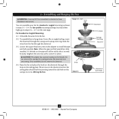
... Assembly Screws Steps 6-1 - 6-2 Use without grommet Blade Mounting Screw Step 6-4 10 42508-01 • 09/23/08 • Hunter Fan Company If your fan has grommets, insert them by hand into the holes on the blades. 6-2. For each blade to the fan. Attach each blade, insert one blade mounting screw through the blade iron, and attach lightly to a blade iron using three blade assembly screws. This is normal. 6-3. Remove the blade mounting screws and rubber shipping bumpers from the motor. 6 • Assembling the Blades Hunter fans use several styles of fan blade irons (brackets...
... Assembly Screws Steps 6-1 - 6-2 Use without grommet Blade Mounting Screw Step 6-4 10 42508-01 • 09/23/08 • Hunter Fan Company If your fan has grommets, insert them by hand into the holes on the blades. 6-2. For each blade to the fan. Attach each blade, insert one blade mounting screw through the blade iron, and attach lightly to a blade iron using three blade assembly screws. This is normal. 6-3. Remove the blade mounting screws and rubber shipping bumpers from the motor. 6 • Assembling the Blades Hunter fans use several styles of fan blade irons (brackets...
Owner's Manual
Page 11
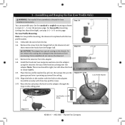
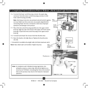
... fan model. 7-1. The steps below direct you whether or not you have uninstalled the light fixture, continue with step 7-6 now. WARNING: Use only the light fixture supplied with an integrated light fixture assembly and an optional switch housing cap and plug button. Once you are firmly situated in the switch housing and light fixture falling. 7-5. See "Uninstalling the Light Fixture" on step 7-11. Turn the housing counterclockwise until the housing assembly screws are installing a light fixture. Steps 7-1 - 7-3 Housing Assembly Screw Upper Switch Housing...
... fan model. 7-1. The steps below direct you whether or not you have uninstalled the light fixture, continue with step 7-6 now. WARNING: Use only the light fixture supplied with an integrated light fixture assembly and an optional switch housing cap and plug button. Once you are firmly situated in the switch housing and light fixture falling. 7-5. See "Uninstalling the Light Fixture" on step 7-11. Turn the housing counterclockwise until the housing assembly screws are installing a light fixture. Steps 7-1 - 7-3 Housing Assembly Screw Upper Switch Housing...
Owner's Manual
Page 12
... the lower switch housing to the light fixture. Raise the shade to the upper switch housing Plug Connector Lower Switch Housing 7-8. Exceeding that restricts the light kit to a maximum of lights may result in the upper and lower switch housings. To install each ). Align the side screw holes in fire hazard or improper operation. Steps 7-8 - 7-10 12 42508-01 • 09/23/08 • Hunter Fan Company Shade Bulb To attach the lower switch housing, connect the upper plug connector from the motor to the...
... the lower switch housing to the light fixture. Raise the shade to the upper switch housing Plug Connector Lower Switch Housing 7-8. Exceeding that restricts the light kit to a maximum of lights may result in the upper and lower switch housings. To install each ). Align the side screw holes in fire hazard or improper operation. Steps 7-8 - 7-10 12 42508-01 • 09/23/08 • Hunter Fan Company Shade Bulb To attach the lower switch housing, connect the upper plug connector from the motor to the...

Owner's Manual
Page 13
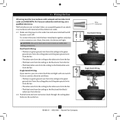
...-01 • 09/23/08 • Hunter Fan Company Reattach the breakaway connector to the Speed lower switch housing. Thread the bellmouth nut over the pull chain and hand tighten the bellmouth nut. Fan Speed Switch 7-21. Switch Housing 7-18. Locate the reversing switch and carefully remove Fan the two screws holding the reversing switch to the pull chain. 7-19. Bellmouth Nuts 7-14. You Steps 7-11 - 7-16 Reversing Switch Light Assembly Housing must remove the wiring harness and its components and are...
...-01 • 09/23/08 • Hunter Fan Company Reattach the breakaway connector to the Speed lower switch housing. Thread the bellmouth nut over the pull chain and hand tighten the bellmouth nut. Fan Speed Switch 7-21. Switch Housing 7-18. Locate the reversing switch and carefully remove Fan the two screws holding the reversing switch to the pull chain. 7-19. Bellmouth Nuts 7-14. You Steps 7-11 - 7-16 Reversing Switch Light Assembly Housing must remove the wiring harness and its components and are...
Owner's Manual
Page 14
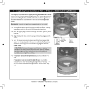
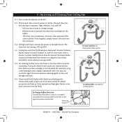
.... The fan pull chain controls power to the light fixture. Clean painted and high-gloss blades in warm weather to the fan. 8-2. The light pull chain controls the power to the fan. Reversing Switch 14 42508-01 • 09/23/08 • Hunter Fan Company 8 • Operating and Cleaning Your Ceiling Fan 8-1. A vacuum cleaner brush nozzle can remove heavier dust. You may use an artistic agent, but never abrasive cleaning agents as the fan finish. Clean wood finish blades with a direct breeze. Occasionally, apply a light coat...
.... The fan pull chain controls power to the light fixture. Clean painted and high-gloss blades in warm weather to the fan. 8-2. The light pull chain controls the power to the fan. Reversing Switch 14 42508-01 • 09/23/08 • Hunter Fan Company 8 • Operating and Cleaning Your Ceiling Fan 8-1. A vacuum cleaner brush nozzle can remove heavier dust. You may use an artistic agent, but never abrasive cleaning agents as the fan finish. Clean wood finish blades with a direct breeze. Occasionally, apply a light coat...
Owner's Manual
Page 15
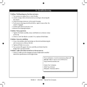
... switch housing. 4. Push motor reversing switch firmly left or right to balance the fan. 2. Tighten the blade assembly screws and blade iron armature screws until snug. 2. If your fan wobbles when operating, use the enclosed balancing kit and instructions to ensure that the hanger ball is on the light socket. Hunter Fan Company 2500 Frisco Avenue Memphis, Tennessee 38114 15 42508-01 • 09/23/08 • Hunter Fan Company Pull the pull chain to the wiring the fan section. 3. Problem: Lights...
... switch housing. 4. Push motor reversing switch firmly left or right to balance the fan. 2. Tighten the blade assembly screws and blade iron armature screws until snug. 2. If your fan wobbles when operating, use the enclosed balancing kit and instructions to ensure that the hanger ball is on the light socket. Hunter Fan Company 2500 Frisco Avenue Memphis, Tennessee 38114 15 42508-01 • 09/23/08 • Hunter Fan Company Pull the pull chain to the wiring the fan section. 3. Problem: Lights...
Parts Guide
Page 1
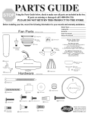
... Guide below, check to Scale) 150 Globe/Shade 170 Switch Housing, Alternate 29 Switch Housing Cover 41 Switch Housing Plug Button 65 Wood Screw 64 Wood Screw 71 Isolator 68 Flat Washer 66 Blade Grommet 27 Low Profile Washer 100 Locking Screw 101 Canopy Screw 69 Screw, Machine, 6-32 70 Wire Nut 156 Thumb screw 47 Screw, Blade 8 Setscrew R Iron Armature 67 Blade Assembly Screw Date Purchased Where Purchased 7 Hanger Ball / Downrod Assembly 4 Canopy Trim Ring 3 Canopy 75 Balancing Kit 28 Switch / Housing Assembly Missing / Broken Parts: Call 1-888-830-1326 Fan does not work...
... Guide below, check to Scale) 150 Globe/Shade 170 Switch Housing, Alternate 29 Switch Housing Cover 41 Switch Housing Plug Button 65 Wood Screw 64 Wood Screw 71 Isolator 68 Flat Washer 66 Blade Grommet 27 Low Profile Washer 100 Locking Screw 101 Canopy Screw 69 Screw, Machine, 6-32 70 Wire Nut 156 Thumb screw 47 Screw, Blade 8 Setscrew R Iron Armature 67 Blade Assembly Screw Date Purchased Where Purchased 7 Hanger Ball / Downrod Assembly 4 Canopy Trim Ring 3 Canopy 75 Balancing Kit 28 Switch / Housing Assembly Missing / Broken Parts: Call 1-888-830-1326 Fan does not work...
Parts Guide
Page 2
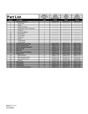
...97504-05 New Bronze Part # ...Part List Item # 2 3 4 7 8 27 64 65 68 71 100 101 28 29 41 44 46 47 66 67 69 70 75 150 156 170 Item Name * Hanging System Kit Ceiling Plate Canopy Canopy Trim Ring Hanger Ball / Downrod Assembly Set Screw Low Profile Washer Screw, Wood Screw, Wood Flat Washer Isolator Locking Screw Canopy Screw Switch/Housing Assembly Switch Housing Cover Switch Housing Plug Button Blade Iron Set Blade Set Screw, Blade Iron Armature * Hardware Kit Blade Grommet Blade Assembly Screw Screw, Machine, 6-32 Wire Nut Balancing Kit Globe/Shade Thumb Screw Switch Housing, Alternate Model...
...97504-05 New Bronze Part # ...Part List Item # 2 3 4 7 8 27 64 65 68 71 100 101 28 29 41 44 46 47 66 67 69 70 75 150 156 170 Item Name * Hanging System Kit Ceiling Plate Canopy Canopy Trim Ring Hanger Ball / Downrod Assembly Set Screw Low Profile Washer Screw, Wood Screw, Wood Flat Washer Isolator Locking Screw Canopy Screw Switch/Housing Assembly Switch Housing Cover Switch Housing Plug Button Blade Iron Set Blade Set Screw, Blade Iron Armature * Hardware Kit Blade Grommet Blade Assembly Screw Screw, Machine, 6-32 Wire Nut Balancing Kit Globe/Shade Thumb Screw Switch Housing, Alternate Model...


