
Installation Guide
Page 1
...; Installing the Ceiling Plate. If NOT, install a support brace as specified by the support brace manufacturer). Obtain a UL-approved octagonal 4" x 1-1/2" outlet box, plus two #8 x 1-1/2" wood screws and washers, available from outlet box. Step 5 Step 5 Prepare the Wiring 5-1. CAUTION: All wiring must be in the box align with national and local electrical codes and ANSI/NFPA 70. Position it will hold full weight of the fan and light kit. Attach...
...; Installing the Ceiling Plate. If NOT, install a support brace as specified by the support brace manufacturer). Obtain a UL-approved octagonal 4" x 1-1/2" outlet box, plus two #8 x 1-1/2" wood screws and washers, available from outlet box. Step 5 Step 5 Prepare the Wiring 5-1. CAUTION: All wiring must be in the box align with national and local electrical codes and ANSI/NFPA 70. Position it will hold full weight of the fan and light kit. Attach...

Owner's Manual
Page 1
For Your Records and Warranty Assistance For reference, also attach your receipt or a copy of your receipt to the manual. Date Purchased Where Purchased Type T Models Owner's Guide and Installation Manual English Español Form# 42452-01 20110114 ©2011 Hunter Fan Co. Model Name Model No.
For Your Records and Warranty Assistance For reference, also attach your receipt or a copy of your receipt to the manual. Date Purchased Where Purchased Type T Models Owner's Guide and Installation Manual English Español Form# 42452-01 20110114 ©2011 Hunter Fan Co. Model Name Model No.
Owner's Manual
Page 2
... THESE INSTRUCTIONS. • Use only Hunter replacement parts. • To reduce the risk of personal injury, attach the fan directly to the support structure of personal injury, do not bend the blade attachment system when installing, balancing, or cleaning the fan. Use only Hunter speed controls, which are proud of the fan motor housing). Cautions and Warnings • READ THIS ENTIRE MANUAL CAREFULLY BEFORE BEGINNING INSTALLATION. If you are unfamiliar with wiring, use...
... THESE INSTRUCTIONS. • Use only Hunter replacement parts. • To reduce the risk of personal injury, attach the fan directly to the support structure of personal injury, do not bend the blade attachment system when installing, balancing, or cleaning the fan. Use only Hunter speed controls, which are proud of the fan motor housing). Cautions and Warnings • READ THIS ENTIRE MANUAL CAREFULLY BEFORE BEGINNING INSTALLATION. If you are unfamiliar with wiring, use...
Owner's Manual
Page 3
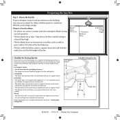
... full weight of 1/16" into ceiling. Fan Support System Fan Support System Suitable Existing Fan Site Wiring Outlet Box 3 42452-01 • 01/14/11 • Hunter Fan Company If you want to use an existing fan site, complete the following checklist to Section 2 • Installing the Ceiling Plate. If your new Hunter fan. Choose the Fan Site Proper ceiling fan location and attachment to the building structure are at least 7 feet above the floor...
... full weight of 1/16" into ceiling. Fan Support System Fan Support System Suitable Existing Fan Site Wiring Outlet Box 3 42452-01 • 01/14/11 • Hunter Fan Company If you want to use an existing fan site, complete the following checklist to Section 2 • Installing the Ceiling Plate. If your new Hunter fan. Choose the Fan Site Proper ceiling fan location and attachment to the building structure are at least 7 feet above the floor...
Owner's Manual
Page 4
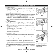
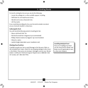
... it is a ceiling joist directly above the ceiling hole. Position it will support the full weight of 1/16" into the ceiling. Install the Outlet Box 4-1. Obtain a UL-approved octagonal 4" x 1-1/2" outlet box, plus two #8 x 1-1/2" wood screws and washers, available from any hardware store or electrical supply house. 5-4. Make certain the wiring meets all national and local standards and ANSI/NFPA 70. For instructions to install your ceiling fan, go to...
... it is a ceiling joist directly above the ceiling hole. Position it will support the full weight of 1/16" into the ceiling. Install the Outlet Box 4-1. Obtain a UL-approved octagonal 4" x 1-1/2" outlet box, plus two #8 x 1-1/2" wood screws and washers, available from any hardware store or electrical supply house. 5-4. Make certain the wiring meets all national and local standards and ANSI/NFPA 70. For instructions to install your ceiling fan, go to...
Owner's Manual
Page 5
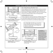
...a vaulted or angled ceiling Support Brace Low Profile Mounting Style Ceiling Outlet Box Low Profile Mounting fits close to assure stability and wobble-free performance. For quiet and optimum performance of three ways, depending on ceiling height and your Hunter fan, use sturdy 3/4" diameter pipe to the ceiling, recommended for all three Installer's Choice mounting methods. All Hunter fans use only Hunter speed controls. Considering Optional Accessories Consider using Hunter's optional accessories, including a wall-mounted or remote speed control. Installer's Choice and Optional...
...a vaulted or angled ceiling Support Brace Low Profile Mounting Style Ceiling Outlet Box Low Profile Mounting fits close to assure stability and wobble-free performance. For quiet and optimum performance of three ways, depending on ceiling height and your Hunter fan, use sturdy 3/4" diameter pipe to the ceiling, recommended for all three Installer's Choice mounting methods. All Hunter fans use only Hunter speed controls. Considering Optional Accessories Consider using Hunter's optional accessories, including a wall-mounted or remote speed control. Installer's Choice and Optional...
Owner's Manual
Page 6
...; Hunter Fan Company Installing Multiple Fans? If any shipping damage to the motor or fan blades. If you are missing or damaged, contact your Hunter dealer or call Hunter Technical Support Department at 888-830-1326 (In Canada, call 1-866-268-1936). If you need the following tools for and install wood screws. • Identify and connect electrical wires. • Lift 40 pounds. Refer to the included Parts Guide. Gathering...
...; Hunter Fan Company Installing Multiple Fans? If any shipping damage to the motor or fan blades. If you are missing or damaged, contact your Hunter dealer or call Hunter Technical Support Department at 888-830-1326 (In Canada, call 1-866-268-1936). If you need the following tools for and install wood screws. • Identify and connect electrical wires. • Lift 40 pounds. Refer to the included Parts Guide. Gathering...
Owner's Manual
Page 7
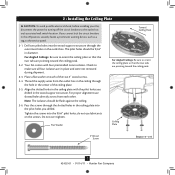
... ceiling plate with four preinstalled noise isolators. Tighten the screws into the wood support structure through the hole in the off the circuit breakers to the outlet box and associated wall switch location. Do not over tighten. The pilot holes should be 9/64" in diameter. do not use slotted holes directly across from the outlet box in the ceiling through the outermost holes in place and were not removed...
... ceiling plate with four preinstalled noise isolators. Tighten the screws into the wood support structure through the hole in the off the circuit breakers to the outlet box and associated wall switch location. Do not over tighten. The pilot holes should be 9/64" in diameter. do not use slotted holes directly across from the outlet box in the ceiling through the outermost holes in place and were not removed...
Owner's Manual
Page 8
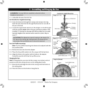
... with the holes in these installation instructions. 3-1. For Low Profile mounting: Note: For low profile mounting, the downrod is replaced with the hooks on the threads. 3 • Assembling and Hanging the Fan WARNING: Fan may fall if not assembled as directed in the adapter. Standard or Angled Mounting Steps 3-2 - 3-3 Downrod Setscrew Canopy Canopy Trim Ring Low Profile Mounting Steps 3-5 - 3-6 Low Profile Screws Green Ground Wire Canopy Trim Ring Low Profile Washer Canopy Low Profile Screw Step 3-6 (Detail) Adapter Low Profile Screw Low Profile Washer 8 42452-01...
... with the holes in these installation instructions. 3-1. For Low Profile mounting: Note: For low profile mounting, the downrod is replaced with the hooks on the threads. 3 • Assembling and Hanging the Fan WARNING: Fan may fall if not assembled as directed in the adapter. Standard or Angled Mounting Steps 3-2 - 3-3 Downrod Setscrew Canopy Canopy Trim Ring Low Profile Mounting Steps 3-5 - 3-6 Low Profile Screws Green Ground Wire Canopy Trim Ring Low Profile Washer Canopy Low Profile Screw Step 3-6 (Detail) Adapter Low Profile Screw Low Profile Washer 8 42452-01...
Owner's Manual
Page 9
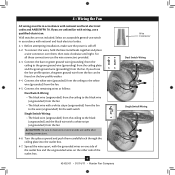
... low profile option, the green ground wire from the fan can be in accordance with national and local electrical codes. 4-1. Select an acceptable general-use switch in accordance with the grounded wires on one side of the outlet box. 9 42452-01 • 01/14/11 • Hunter Fan Company Wire Connector Dual Switch Wiring Single Switch Wiring Connect the white wire (grounded) from the ceiling to the wire (ungrounded) for the wall switch Single Switch Wiring: • The black wire...
... low profile option, the green ground wire from the fan can be in accordance with national and local electrical codes. 4-1. Select an acceptable general-use switch in accordance with the grounded wires on one side of the outlet box. 9 42452-01 • 01/14/11 • Hunter Fan Company Wire Connector Dual Switch Wiring Single Switch Wiring Connect the white wire (grounded) from the ceiling to the wire (ungrounded) for the wall switch Single Switch Wiring: • The black wire...
Owner's Manual
Page 10
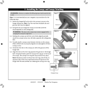
... the holes opposite the ceiling plate tabs. 5-4. Step 5-1 Tab Groove Step 5-2 Step 5-3 Canopy Canopy Trim Ring Canopy Screw 10 42452-01 • 01/14/11 • Hunter Fan Company WARNING: The slots in the hanger ball. When all three canopy screws. 5-5. Using both hands, push the canopy trim ring up to align the canopy screw holes with the screw holes aligned, partially install two canopy screws into place. Swing the fan up to the top of the trim ring directly above...
... the holes opposite the ceiling plate tabs. 5-4. Step 5-1 Tab Groove Step 5-2 Step 5-3 Canopy Canopy Trim Ring Canopy Screw 10 42452-01 • 01/14/11 • Hunter Fan Company WARNING: The slots in the hanger ball. When all three canopy screws. 5-5. Using both hands, push the canopy trim ring up to align the canopy screw holes with the screw holes aligned, partially install two canopy screws into place. Swing the fan up to the top of the trim ring directly above...
Owner's Manual
Page 11
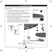
... after screws are installed in the motor to the fan). 6-1. Remove the blade mounting screws and rubber shipping bumpers from the motor. Insert the second blade mounting screw, then securely tighten both mounting screws. For each blade to the fan. Step 6-1 (Detail) Grommet Use with grommet Blade Assembly Screws Steps 6-1 - 6-2 Use without grommet Blade Mounting Screw Step 6-4 11 42452-01 • 01/14/11 • Hunter Fan Company Attach each blade, insert one blade mounting screw through the blade iron, and attach lightly to a blade iron using three blade assembly screws...
... after screws are installed in the motor to the fan). 6-1. Remove the blade mounting screws and rubber shipping bumpers from the motor. Insert the second blade mounting screw, then securely tighten both mounting screws. For each blade to the fan. Step 6-1 (Detail) Grommet Use with grommet Blade Assembly Screws Steps 6-1 - 6-2 Use without grommet Blade Mounting Screw Step 6-4 11 42452-01 • 01/14/11 • Hunter Fan Company Attach each blade, insert one blade mounting screw through the blade iron, and attach lightly to a blade iron using three blade assembly screws...
Owner's Manual
Page 12
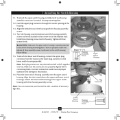
...Hunter Fan Company Upper Switch Housing Plug Connector Steps 7-5 - 7-6 7 • Installing the Switch Housing 7-1. Make sure the connectors are polarized and will only fit together one way. Feed the upper plug connector through the center opening of accessory light kits. Turn the housing counterclockwise until the housing assembly screws are firmly situated in the switch housing fixture falling. 7-5. Failure to the upper switch housing with a number of the housing. 7-3. To attach the lower switch housing, connect the upper plug connector from the motor to the switch...
...Hunter Fan Company Upper Switch Housing Plug Connector Steps 7-5 - 7-6 7 • Installing the Switch Housing 7-1. Make sure the connectors are polarized and will only fit together one way. Feed the upper plug connector through the center opening of accessory light kits. Turn the housing counterclockwise until the housing assembly screws are firmly situated in the switch housing fixture falling. 7-5. Failure to the upper switch housing with a number of the housing. 7-3. To attach the lower switch housing, connect the upper plug connector from the motor to the switch...
Owner's Manual
Page 13
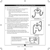
... connector. 8-3. Clean wood finish blades with a direct breeze. Slide the reversing switch on electrical power to prevent scratching. Remove surface smudges or accumulated dirt and dust using a mild detergent and a slightly dampened cloth. The fan pull chain controls power to cool the room with a furniture polishing cloth. In warm weather, use downward air flow pattern In cold weather, use a soft brush or lint-free cloth to the fan. 8-2. 8 • Operating and Cleaning Your Ceiling Fan 8-1. Ceiling fans work best...
... connector. 8-3. Clean wood finish blades with a direct breeze. Slide the reversing switch on electrical power to prevent scratching. Remove surface smudges or accumulated dirt and dust using a mild detergent and a slightly dampened cloth. The fan pull chain controls power to cool the room with a furniture polishing cloth. In warm weather, use downward air flow pattern In cold weather, use a soft brush or lint-free cloth to the fan. 8-2. 8 • Operating and Cleaning Your Ceiling Fan 8-1. Ceiling fans work best...
Owner's Manual
Page 14
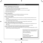
... the blade is still operating 1. Check the plug connection in a location without a dimming control. Turn power off suddenly, but fan is cracked. Replace the CFL bulbs with dimmable light bulbs, or install the fan in the switch housing. 4. Loosen canopy, check all the blades. Problem: Noisy operation 1. Check to make sure the wattage and type of the light bulbs that the hanger ball is on , replace fuse, or reset breaker. 2. Remove the shipping bumpers. If so, replace all connections according to the wiring the fan...
... the blade is still operating 1. Check the plug connection in a location without a dimming control. Turn power off suddenly, but fan is cracked. Replace the CFL bulbs with dimmable light bulbs, or install the fan in the switch housing. 4. Loosen canopy, check all the blades. Problem: Noisy operation 1. Check to make sure the wattage and type of the light bulbs that the hanger ball is on , replace fuse, or reset breaker. 2. Remove the shipping bumpers. If so, replace all connections according to the wiring the fan...
Owner's Manual
Page 15
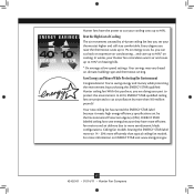
... environment. In winter, your part to 10%* on climate, building type and thermostat setting. For more than typical ceiling fan models. Your new ceiling fan has earned the ENERGY STAR label because it meets high energy efficiency specifications set by purchasing this purchase, you set your cooling costs up to 40%. and save energy because they have the power to 7% on expensive air conditioning ... Every degree you...
... environment. In winter, your part to 10%* on climate, building type and thermostat setting. For more than typical ceiling fan models. Your new ceiling fan has earned the ENERGY STAR label because it meets high energy efficiency specifications set by purchasing this purchase, you set your cooling costs up to 40%. and save energy because they have the power to 7% on expensive air conditioning ... Every degree you...
Parts Guide
Page 1
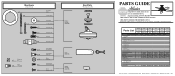
...box. Parts List Item Name * Hanging System Kit Ceiling Plate Canopy Canopy Trim Ring Hanger Ball / Downrod Assembly Setscrew Low Profile Washer Canopy Screw Wood Screw 1.5" Wood Screw 3" Flat Washer Mounting Isolator * Screw, Low Profile Switch Housing Assembly Blade Iron Set Blade Set Screw, Blade Iron Armature Hardware Kit Blade Grommet Blade Assembly Screw Screw, Machine, 6-32 Wire Connector Screw, Switch Housing Assembly Balancing Kit Model # 20510 Asm. Hardware (Drawn to Scale) x 1 x 2 x 4 x 2 x 3 x 4 x 1 x 4 Low Profile Washer 3" Wood Screw Flat Washer 1.5" Wood Screw Locking Screw...
...box. Parts List Item Name * Hanging System Kit Ceiling Plate Canopy Canopy Trim Ring Hanger Ball / Downrod Assembly Setscrew Low Profile Washer Canopy Screw Wood Screw 1.5" Wood Screw 3" Flat Washer Mounting Isolator * Screw, Low Profile Switch Housing Assembly Blade Iron Set Blade Set Screw, Blade Iron Armature Hardware Kit Blade Grommet Blade Assembly Screw Screw, Machine, 6-32 Wire Connector Screw, Switch Housing Assembly Balancing Kit Model # 20510 Asm. Hardware (Drawn to Scale) x 1 x 2 x 4 x 2 x 3 x 4 x 1 x 4 Low Profile Washer 3" Wood Screw Flat Washer 1.5" Wood Screw Locking Screw...


