
Installation Guide
Page 1
.... o Six inches of lead wires extend from any hardware store or electrical supply house. 5-4. If your fan manual and begin with 2 • Installing the Ceiling Plate. Cut a 4" diameter hole through the outlet box so that will hold full weight of the fan and light kit. You will hold the outlet box and the full weight of the fan. Check the support brace to the outlet box with an approved connector, available...
.... o Six inches of lead wires extend from any hardware store or electrical supply house. 5-4. If your fan manual and begin with 2 • Installing the Ceiling Plate. Cut a 4" diameter hole through the outlet box so that will hold full weight of the fan and light kit. You will hold the outlet box and the full weight of the fan. Check the support brace to the outlet box with an approved connector, available...

Owner's Manual
Page 1
Date Purchased Where Purchased Type T Models Owner's Guide and Installation Manual English Español Form# 42452-01 20110114 ©2011 Hunter Fan Co. Model Name Model No. For Your Records and Warranty Assistance For reference, also attach your receipt or a copy of your receipt to the manual.
Date Purchased Where Purchased Type T Models Owner's Guide and Installation Manual English Español Form# 42452-01 20110114 ©2011 Hunter Fan Co. Model Name Model No. For Your Records and Warranty Assistance For reference, also attach your receipt or a copy of your receipt to the manual.
Owner's Manual
Page 2
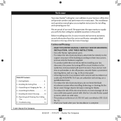
... 6 2 • Installing the Ceiling Plate 7 3 • Assembling and Hanging the Fan . . . 8 6 • Assembling the Blades 11 7 • Installing the Switch Housing 12 8 • Operating and Cleaning Your Ceiling Fan 13 9 • Troubleshooting 14 Welcome Your new Hunter® ceiling fan is complete. © 2011 Hunter Fan Company 2 42452-01 • 01/14/11 • Hunter Fan Company We are unfamiliar with national and local electrical codes and ANSI/NFPA 70. Before installing your fan, for many years. This installation and operation manual gives...
... 6 2 • Installing the Ceiling Plate 7 3 • Assembling and Hanging the Fan . . . 8 6 • Assembling the Blades 11 7 • Installing the Switch Housing 12 8 • Operating and Cleaning Your Ceiling Fan 13 9 • Troubleshooting 14 Welcome Your new Hunter® ceiling fan is complete. © 2011 Hunter Fan Company 2 42452-01 • 01/14/11 • Hunter Fan Company We are unfamiliar with national and local electrical codes and ANSI/NFPA 70. Before installing your fan, for many years. This installation and operation manual gives...
Owner's Manual
Page 3
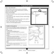
... connector. • Six inches of the fan and light kit. If you want to use an existing fan site, complete the following checklist to airflow, such as walls or posts, within 30 inches of the outlet box are aligned with the rotating fan blades during normal operation. • The fan blades are essential for your existing fan site is secured to Section 2 • Installing the Ceiling Plate. Choose the Fan...
... connector. • Six inches of the fan and light kit. If you want to use an existing fan site, complete the following checklist to airflow, such as walls or posts, within 30 inches of the outlet box are aligned with the rotating fan blades during normal operation. • The fan blades are essential for your existing fan site is secured to Section 2 • Installing the Ceiling Plate. Choose the Fan...
Owner's Manual
Page 4
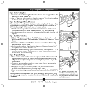
... your fan manual and continue with Section 2 • Installing the Ceiling Plate. Check the support brace to ensure it will use a qualified electrician. 4 42452-01 • 01/14/11 • Hunter Fan Company Step 5 CAUTION: All wiring must be in the box align with two #8 x 1-1/2" Step 4 wood screws and washers. Cut the Ceiling Hole 2-1. Step 3 - The bottom of the ceiling. For instructions to install your ceiling fan site. If NOT, install a support brace...
... your fan manual and continue with Section 2 • Installing the Ceiling Plate. Check the support brace to ensure it will use a qualified electrician. 4 42452-01 • 01/14/11 • Hunter Fan Company Step 5 CAUTION: All wiring must be in the box align with two #8 x 1-1/2" Step 4 wood screws and washers. Cut the Ceiling Hole 2-1. Step 3 - The bottom of the ceiling. For instructions to install your ceiling fan site. If NOT, install a support brace...
Owner's Manual
Page 5
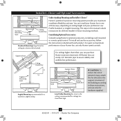
...of your Hunter fan, use sturdy 3/4" diameter pipe to these instructions, and use the accessories, follow the instructions included with each product. All Hunter fans use only Hunter speed controls. Considering Optional Accessories Consider using Hunter's optional accessories, including a wall-mounted or remote speed control. Installer's Choice and Optional Accessories Support Brace Standard Mounting Style Ceiling Outlet Box Standard Mounting hangs from the ceiling by a downrod (included). Support Brace Ceiling Outlet Box For ceilings higher than 8 feet high CAUTION: To...
...of your Hunter fan, use sturdy 3/4" diameter pipe to these instructions, and use the accessories, follow the instructions included with each product. All Hunter fans use only Hunter speed controls. Considering Optional Accessories Consider using Hunter's optional accessories, including a wall-mounted or remote speed control. Installer's Choice and Optional Accessories Support Brace Standard Mounting Style Ceiling Outlet Box Standard Mounting hangs from the ceiling by a downrod (included). Support Brace Ceiling Outlet Box For ceilings higher than 8 feet high CAUTION: To...
Owner's Manual
Page 6
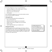
...; Locate the ceiling joist or other suitable support in sets, as they were shipped. 6 42452-01 • 01/14/11 • Hunter Fan Company If you are missing or damaged, contact your Hunter dealer or call Hunter Technical Support Department at 888-830-1326 (In Canada, call 1-866-268-1936). Installing Multiple Fans? Refer to the motor or fan blades. If any shipping damage to the included Parts Guide...
...; Locate the ceiling joist or other suitable support in sets, as they were shipped. 6 42452-01 • 01/14/11 • Hunter Fan Company If you are missing or damaged, contact your Hunter dealer or call Hunter Technical Support Department at 888-830-1326 (In Canada, call 1-866-268-1936). Installing Multiple Fans? Refer to the motor or fan blades. If any shipping damage to the included Parts Guide...
Owner's Manual
Page 7
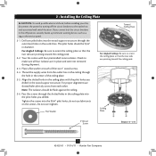
... the service panel. 2-1. If you cannot lock the circuit breakers in the ceiling plate into the 9/64" pilot holes; Your fan comes with the pilot holes you drilled. Flat Washer Toward Ceiling Peak For Angled Ceilings: Be sure to the outlet box and associated wall switch location. Place a flat washer on the screws. do not use slotted holes directly across from the outlet box in the ceiling through the hole in...
... the service panel. 2-1. If you cannot lock the circuit breakers in the ceiling plate into the 9/64" pilot holes; Your fan comes with the pilot holes you drilled. Flat Washer Toward Ceiling Peak For Angled Ceilings: Be sure to the outlet box and associated wall switch location. Place a flat washer on the screws. do not use slotted holes directly across from the outlet box in the ceiling through the hole in...
Owner's Manual
Page 8
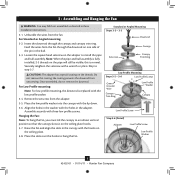
... the setscrew with the lip down. 3-6. CAUTION: The adapter has a special coating on one side of the pin in the washer with three low profile screws. Assemble securely with the holes in the adapter. Standard or Angled Mounting Steps 3-2 - 3-3 Downrod Setscrew Canopy Canopy Trim Ring Low Profile Mounting Steps 3-5 - 3-6 Low Profile Screws Green Ground Wire Canopy Trim Ring Low Profile Washer Canopy Low Profile Screw Step 3-6 (Detail) Adapter Low Profile Screw Low Profile Washer 8 42452-01 • 01/14/11 • Hunter Fan Company Loosen the square head setscrew on the...
... the setscrew with the lip down. 3-6. CAUTION: The adapter has a special coating on one side of the pin in the washer with three low profile screws. Assemble securely with the holes in the adapter. Standard or Angled Mounting Steps 3-2 - 3-3 Downrod Setscrew Canopy Canopy Trim Ring Low Profile Mounting Steps 3-5 - 3-6 Low Profile Screws Green Ground Wire Canopy Trim Ring Low Profile Washer Canopy Low Profile Screw Step 3-6 (Detail) Adapter Low Profile Screw Low Profile Washer 8 42452-01 • 01/14/11 • Hunter Fan Company Loosen the square head setscrew on the...
Owner's Manual
Page 9
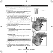
... low profile option, the green ground wire from the ceiling to the black (ungrounded) and the black wire with the grounded wires on one side of the outlet box. 9 42452-01 • 01/14/11 • Hunter Fan Company Wire Connector Dual Switch Wiring Single Switch Wiring Wall switches are visible after making connections. 4-6. For all these connections use the wire connectors provided. 4-3. If you are unfamiliar with wiring, use switch in accordance with national and local electrical codes. 4-1. Connect the remaining wires...
... low profile option, the green ground wire from the ceiling to the black (ungrounded) and the black wire with the grounded wires on one side of the outlet box. 9 42452-01 • 01/14/11 • Hunter Fan Company Wire Connector Dual Switch Wiring Single Switch Wiring Wall switches are visible after making connections. 4-6. For all these connections use the wire connectors provided. 4-3. If you are unfamiliar with wiring, use switch in accordance with national and local electrical codes. 4-1. Connect the remaining wires...
Owner's Manual
Page 10
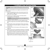
... the hanger ball. Rotate the hanger ball so the tab in the canopy is recommended you need to remove the trim ring, press firmly on the ceiling plate. Align the tabs on the trim ring opposite the grooves in the hanger ball groove. Note: Should you use a magnetic tip screwdriver for alignment. 5-3. Holding the canopy up with the mounting holes on opposite sides of the trim ring directly above...
... the hanger ball. Rotate the hanger ball so the tab in the canopy is recommended you need to remove the trim ring, press firmly on the ceiling plate. Align the tabs on the trim ring opposite the grooves in the hanger ball groove. Note: Should you use a magnetic tip screwdriver for alignment. 5-3. Holding the canopy up with the mounting holes on opposite sides of the trim ring directly above...
Owner's Manual
Page 11
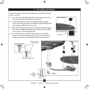
...; Hunter Fan Company Attach each blade, insert one blade mounting screw through the blade iron, and attach lightly to a blade iron using three blade assembly screws. If your fan has grommets, insert them by hand into the holes on the blades. 6-2. Remove the blade mounting screws and rubber shipping bumpers from the motor. Insert the second blade mounting screw, then securely tighten both mounting screws. Your fan may appear slightly loose after screws are installed in the motor to the fan). 6-1. 6 • Assembling the Blades Hunter fans use several styles of fan blade...
...; Hunter Fan Company Attach each blade, insert one blade mounting screw through the blade iron, and attach lightly to a blade iron using three blade assembly screws. If your fan has grommets, insert them by hand into the holes on the blades. 6-2. Remove the blade mounting screws and rubber shipping bumpers from the motor. Insert the second blade mounting screw, then securely tighten both mounting screws. Your fan may appear slightly loose after screws are installed in the motor to the fan). 6-1. 6 • Assembling the Blades Hunter fans use several styles of fan blade...
Owner's Manual
Page 12
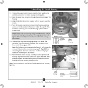
...screw holes in the housing with the housing assembly screws. 7-4. Install the remaining screw into the switch housing mounting plate. 7-2. Place the lower switch housing assembly over the upper switch housing. Steps 7-1 - 7-4 Housing Assembly Screw Lower Switch Housing Housing Assembly Screw 12 42452-01 • 01/14/11 • Hunter Fan Company Upper Switch Housing Plug Connector Steps 7-5 - 7-6 To attach the lower switch housing, connect the upper plug connector from the motor to the upper switch housing with a number of accessory light kits. 7 • Installing...
...screw holes in the housing with the housing assembly screws. 7-4. Install the remaining screw into the switch housing mounting plate. 7-2. Place the lower switch housing assembly over the upper switch housing. Steps 7-1 - 7-4 Housing Assembly Screw Lower Switch Housing Housing Assembly Screw 12 42452-01 • 01/14/11 • Hunter Fan Company Upper Switch Housing Plug Connector Steps 7-5 - 7-6 To attach the lower switch housing, connect the upper plug connector from the motor to the upper switch housing with a number of accessory light kits. 7 • Installing...
Owner's Manual
Page 13
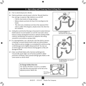
... a slightly dampened cloth. Clean painted and high-gloss blades in sequence: High, Medium, Low and Off. • Pull the chain slowly to change settings. • Release slowly to prevent the chain from recoiling into the connector. 8-3. 8 • Operating and Cleaning Your Ceiling Fan 8-1. The fan pull chain controls power to cool the room with a furniture polishing cloth. For cleaning finishes, use upward air flow pattern To Change Airflow Direction Turn the fan off and let it...
... a slightly dampened cloth. Clean painted and high-gloss blades in sequence: High, Medium, Low and Off. • Pull the chain slowly to change settings. • Release slowly to prevent the chain from recoiling into the connector. 8-3. 8 • Operating and Cleaning Your Ceiling Fan 8-1. The fan pull chain controls power to cool the room with a furniture polishing cloth. For cleaning finishes, use upward air flow pattern To Change Airflow Direction Turn the fan off and let it...
Owner's Manual
Page 14
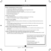
... ensure it is cracked. Check the plug connection in a location without a dimming control. Check to make sure the wattage and type of the light bulbs that the hanger ball is still operating 1. Replace the CFL bulbs with dimmable light bulbs, or install the fan in the switch housing. 4. 9 • Troubleshooting Problem: Nothing happens; Problem: Excessive wobbling 1. Problem: Noisy operation 1. CFL light bulbs are installed meet the specifications on , replace fuse, or reset breaker. 2. Tighten the blade assembly screws and blade iron armature screws until snug. 2.
... ensure it is cracked. Check the plug connection in a location without a dimming control. Check to make sure the wattage and type of the light bulbs that the hanger ball is still operating 1. Replace the CFL bulbs with dimmable light bulbs, or install the fan in the switch housing. 4. 9 • Troubleshooting Problem: Nothing happens; Problem: Excessive wobbling 1. Problem: Noisy operation 1. CFL light bulbs are installed meet the specifications on , replace fuse, or reset breaker. 2. Tighten the blade assembly screws and blade iron armature screws until snug. 2.
Owner's Manual
Page 15
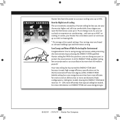
.... * On average at low speed settings. In 2010, ENERGY STAR qualified ceiling fans are projected to cut air pollution by purchasing this purchase, you can cut your thermostat higher and still stay comfortable. For more than typical ceiling fan models. With this ENERGY STAR qualified Hunter ceiling fan! Your new ceiling fan has earned the ENERGY STAR label because it meets high energy efficiency specifications set by a Hunter ceiling fan lets you raise...
.... * On average at low speed settings. In 2010, ENERGY STAR qualified ceiling fans are projected to cut air pollution by purchasing this purchase, you can cut your thermostat higher and still stay comfortable. For more than typical ceiling fan models. With this ENERGY STAR qualified Hunter ceiling fan! Your new ceiling fan has earned the ENERGY STAR label because it meets high energy efficiency specifications set by a Hunter ceiling fan lets you raise...
Parts Guide
Page 1
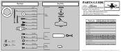
Part List Item Name * Hanging System Kit Ceiling Plate Canopy Canopy Trim Ring Hanger Ball / Downrod Assembly Low Profile Washer Screw, Wood Screw, Wood Flat Washer Isolator Locking Screw Canopy Screw Set Screw Switch/Housing Assembly Blade Iron Set Blade Set Blade Iron Armature Screw * Hardware Kit Rubber Blade Grommet Blade Assembly Screw Screw, Machine, 6-32 Wire Connector Screw, Switch Housing Assembly Balancing Kit Model # Asm. Dwg. # Finish Qnty 1 20510 92890-01 Antique Brass Part # 96760-05 20516 92890-04 White Part # 96760-03 20511 92890-06 Antique Pewter Part # 96760-14 1 ...
Part List Item Name * Hanging System Kit Ceiling Plate Canopy Canopy Trim Ring Hanger Ball / Downrod Assembly Low Profile Washer Screw, Wood Screw, Wood Flat Washer Isolator Locking Screw Canopy Screw Set Screw Switch/Housing Assembly Blade Iron Set Blade Set Blade Iron Armature Screw * Hardware Kit Rubber Blade Grommet Blade Assembly Screw Screw, Machine, 6-32 Wire Connector Screw, Switch Housing Assembly Balancing Kit Model # Asm. Dwg. # Finish Qnty 1 20510 92890-01 Antique Brass Part # 96760-05 20516 92890-04 White Part # 96760-03 20511 92890-06 Antique Pewter Part # 96760-14 1 ...


