
Installation Guide
Page 1
... any hardware store or electrical supply house. 5-4. Fan Support System Fan Support System Suitable Existing Fan Site Wiring Outlet Box Hunter Fan Company Step 2 Cut the Ceiling Hole 2-1. Position it to allow you to recess the bottom of the outlet box a minimum of the fan and light kit. Step 4 Step 4 Install the Outlet Box 4-1. Attach the outlet box directly to the support brace or joist with national and local electrical codes and ANSI/NFPA 70...
... any hardware store or electrical supply house. 5-4. Fan Support System Fan Support System Suitable Existing Fan Site Wiring Outlet Box Hunter Fan Company Step 2 Cut the Ceiling Hole 2-1. Position it to allow you to recess the bottom of the outlet box a minimum of the fan and light kit. Step 4 Step 4 Install the Outlet Box 4-1. Attach the outlet box directly to the support brace or joist with national and local electrical codes and ANSI/NFPA 70...

Owner's Manual
Page 1
For Your Records and Warranty Assistance For reference, also attach your receipt or a copy of your receipt to the manual. Model Name Model No. Catalog No. Date Purchased Where Purchased Type 2 Models Owner's Guide and Installation Manual English Form# 42631-01 20081013 ©2008 Hunter Fan Co.
For Your Records and Warranty Assistance For reference, also attach your receipt or a copy of your receipt to the manual. Model Name Model No. Catalog No. Date Purchased Where Purchased Type 2 Models Owner's Guide and Installation Manual English Form# 42631-01 20081013 ©2008 Hunter Fan Co.
Owner's Manual
Page 2
...; Getting Ready 4 2 • Installing the Ceiling Plate 5 3 • Assembling the Fan 6 4 • Hanging and Wiring the Fan 7 5 • Installing the Canopy and Canopy Trim Ring 8 6 • Assembling the Blades 9 7 • Completing Your Installation With or Without a Light Fixture 10 8 • Operating and Cleaning Your Ceiling Fan 14 9 • Troubleshooting 15 Welcome Your new Hunter® ceiling fan is an addition to the outlet box and associated wall switch location. We appreciate the opportunity to the service panel. • All wiring must be in...
...; Getting Ready 4 2 • Installing the Ceiling Plate 5 3 • Assembling the Fan 6 4 • Hanging and Wiring the Fan 7 5 • Installing the Canopy and Canopy Trim Ring 8 6 • Assembling the Blades 9 7 • Completing Your Installation With or Without a Light Fixture 10 8 • Operating and Cleaning Your Ceiling Fan 14 9 • Troubleshooting 15 Welcome Your new Hunter® ceiling fan is an addition to the outlet box and associated wall switch location. We appreciate the opportunity to the service panel. • All wiring must be in...

Owner's Manual
Page 3
...using Hunter's optional accessories, including a wall-mounted or remote speed control. Installer's Choice and Optional Accessories Support Brace Standard Mounting Style Ceiling Outlet Box Standard Mounting hangs from the ceiling by a downrod (included). Angled Mounting Style 8 12 Angled Mounting recommended for a vaulted or angled ceiling Support Brace Low Profile Mounting Style Ceiling Outlet Box Low Profile Mounting fits close to the ceiling, recommended for all three Installer's Choice mounting methods. All Hunter fans use sturdy 3/4" diameter pipe to these instructions...
...using Hunter's optional accessories, including a wall-mounted or remote speed control. Installer's Choice and Optional Accessories Support Brace Standard Mounting Style Ceiling Outlet Box Standard Mounting hangs from the ceiling by a downrod (included). Angled Mounting Style 8 12 Angled Mounting recommended for a vaulted or angled ceiling Support Brace Low Profile Mounting Style Ceiling Outlet Box Low Profile Mounting fits close to the ceiling, recommended for all three Installer's Choice mounting methods. All Hunter fans use sturdy 3/4" diameter pipe to these instructions...
Owner's Manual
Page 4
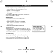
...; Hunter Fan Company If any shipping damage to the motor or fan blades. Preparing the Fan Site Before you need the following : • Locate the ceiling joist or other suitable support in the pullout sheet called "Preparing the Fan Site." 1 • Getting Ready To install a ceiling fan, be sure you can direct you to a licensed installer or electrician. If you begin installing the fan, follow all the instructions in ceiling. • Drill holes...
...; Hunter Fan Company If any shipping damage to the motor or fan blades. Preparing the Fan Site Before you need the following : • Locate the ceiling joist or other suitable support in the pullout sheet called "Preparing the Fan Site." 1 • Getting Ready To install a ceiling fan, be sure you can direct you to a licensed installer or electrician. If you begin installing the fan, follow all the instructions in ceiling. • Drill holes...
Owner's Manual
Page 5
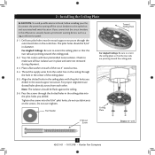
...; Hunter Fan Company Thread the supply wires from each of the ceiling plate. 2-5. Pass the screws through the outermost holes in the ceiling plate with four preinstalled noise isolators. Do not over tighten. For proper alignment use lubricants on each other. Your fan comes with the pilot holes you drilled. Align the slotted holes in the outlet box. 2 • Installing the Ceiling Plate CAUTION: To avoid possible electrical shock, before installing your fan...
...; Hunter Fan Company Thread the supply wires from each of the ceiling plate. 2-5. Pass the screws through the outermost holes in the ceiling plate with four preinstalled noise isolators. Do not over tighten. For proper alignment use lubricants on each other. Your fan comes with the pilot holes you drilled. Align the slotted holes in the outlet box. 2 • Installing the Ceiling Plate CAUTION: To avoid possible electrical shock, before installing your fan...
Owner's Manual
Page 6
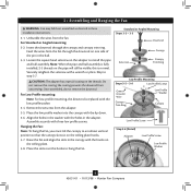
...the downrod through the downrod on the ceiling plate hooks. 3-7. Loosen the square head setscrew on the threads. For Low Profile mounting: Note: For low profile mounting, the downrod is replaced with three low profile screws. Standard or Angled Mounting Steps 3-2 - 3-3 Downrod Setscrew Canopy Canopy Trim Ring Low Profile Mounting Steps 3-5 - 3-6 Low Profile Screws Green Ground Wire Canopy Trim Ring Low Profile Washer Canopy Low Profile Screw Step 3-6 (Detail) Adapter Low Profile Screw Low Profile Washer 6 42631-01 • 10/13/08 • Hunter Fan Company
...the downrod through the downrod on the ceiling plate hooks. 3-7. Loosen the square head setscrew on the threads. For Low Profile mounting: Note: For low profile mounting, the downrod is replaced with three low profile screws. Standard or Angled Mounting Steps 3-2 - 3-3 Downrod Setscrew Canopy Canopy Trim Ring Low Profile Mounting Steps 3-5 - 3-6 Low Profile Screws Green Ground Wire Canopy Trim Ring Low Profile Washer Canopy Low Profile Screw Step 3-6 (Detail) Adapter Low Profile Screw Low Profile Washer 6 42631-01 • 10/13/08 • Hunter Fan Company
Owner's Manual
Page 7
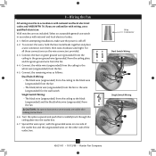
... box and the ungrounded wires on the other side of the outlet box. 7 42631-01 • 10/13/08 • Hunter Fan Company fsdfsdf Wire Connector Dual Switch Wiring Single Switch Wiring Spread the wires apart, with national and local electrical codes. 4-1. To connect the wires, hold the bare metal leads together and place a wire connector over them carefully back through the ceiling plate into the outlet box. 4-7. Select an acceptable general-use the wire connectors...
... box and the ungrounded wires on the other side of the outlet box. 7 42631-01 • 10/13/08 • Hunter Fan Company fsdfsdf Wire Connector Dual Switch Wiring Single Switch Wiring Spread the wires apart, with national and local electrical codes. 4-1. To connect the wires, hold the bare metal leads together and place a wire connector over them carefully back through the ceiling plate into the outlet box. 4-7. Select an acceptable general-use the wire connectors...
Owner's Manual
Page 8
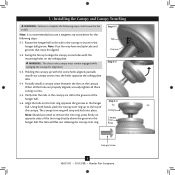
... aligned, securely tighten all three canopy screws. 5-5. Step 5-1 Tab Groove Step 5-2 Step 5-3 Canopy Canopy Trim Ring Canopy Screw 8 42631-01 • 10/13/08 • Hunter Fan Company Align the tabs on the ceiling plate. Note: Should you use a magnetic tip screwdriver for alignment. 5-3. Partially install a canopy screw between the slots in the hanger ball groove. Swing the fan up with the mounting holes on the trim ring opposite the grooves in the...
... aligned, securely tighten all three canopy screws. 5-5. Step 5-1 Tab Groove Step 5-2 Step 5-3 Canopy Canopy Trim Ring Canopy Screw 8 42631-01 • 10/13/08 • Hunter Fan Company Align the tabs on the ceiling plate. Note: Should you use a magnetic tip screwdriver for alignment. 5-3. Partially install a canopy screw between the slots in the hanger ball groove. Swing the fan up with the mounting holes on the trim ring opposite the grooves in the...
Owner's Manual
Page 9
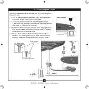
... Step 6-1 (Detail) Grommet Use with grommet Blade Assembly Screws Steps 6-1 - 6-2 Use without grommet Blade Mounting Screw Step 6-4 9 42631-01 • 10/13/08 • Hunter Fan Company For each blade to the fan. Attach each blade, insert one blade mounting screw through the blade iron, and attach lightly to a blade iron using three blade assembly screws. Remove the blade mounting screws and rubber shipping bumpers from the motor. Your fan may appear slightly loose after screws are installed in the motor to the fan). 6-1. Note: Some blade mounting screws are tightened...
... Step 6-1 (Detail) Grommet Use with grommet Blade Assembly Screws Steps 6-1 - 6-2 Use without grommet Blade Mounting Screw Step 6-4 9 42631-01 • 10/13/08 • Hunter Fan Company For each blade to the fan. Attach each blade, insert one blade mounting screw through the blade iron, and attach lightly to a blade iron using three blade assembly screws. Remove the blade mounting screws and rubber shipping bumpers from the motor. Your fan may appear slightly loose after screws are installed in the motor to the fan). 6-1. Note: Some blade mounting screws are tightened...
Owner's Manual
Page 10
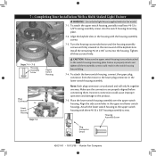
... and will only fit together one way. Tighten all three assembly screws could cause improper operation and damage to the switch housing mounting plate. Incorrect connection could result in the switch housing fixture falling. 7-4. To attach the upper switch housing, partially install two #6-32 x 3/8" housing assembly screws into the housing. Install the remaining #6-32 x 3/8" screw into the switch housing mounting plate. 7-2. Housing Assembly Screw Plug Connector Detail 10 42631-01 • 10/13/08 • Hunter Fan Company Attach the lower switch housing to the...
... and will only fit together one way. Tighten all three assembly screws could cause improper operation and damage to the switch housing mounting plate. Incorrect connection could result in the switch housing fixture falling. 7-4. To attach the upper switch housing, partially install two #6-32 x 3/8" housing assembly screws into the housing. Install the remaining #6-32 x 3/8" screw into the switch housing mounting plate. 7-2. Housing Assembly Screw Plug Connector Detail 10 42631-01 • 10/13/08 • Hunter Fan Company Attach the lower switch housing to the...

Owner's Manual
Page 11
... Light Fixture (Continued) Note: Glass shade style and number of 190 Watts. To install each ). Raise the shade to a maximum of lights may result in fire hazard or improper operation. 11 42631-01 • 10/13/08 • Hunter Fan Company Shade Bulb Thumbscrews Steps 7-7 - 7-8 Note: In compliance with US federal energy regulations, this product may vary. 7-6. Exceeding that limit or the marked limit on this ceiling fan...
... Light Fixture (Continued) Note: Glass shade style and number of 190 Watts. To install each ). Raise the shade to a maximum of lights may result in fire hazard or improper operation. 11 42631-01 • 10/13/08 • Hunter Fan Company Shade Bulb Thumbscrews Steps 7-7 - 7-8 Note: In compliance with US federal energy regulations, this product may vary. 7-6. Exceeding that limit or the marked limit on this ceiling fan...
Owner's Manual
Page 12
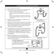
... warmer air trapped at the ceiling around the room without causing a draft. 8-5. Clean wood finish blades with a direct breeze. Reversing Switch 12 42631-01 • 10/13/08 • Hunter Fan Company 8 • Operating and Cleaning Your Ceiling Fan 8-1. Turn on the fan to a complete stop. A vacuum cleaner brush nozzle can remove heavier dust. The light pull chain controls the power to the fan. 8-2. You may use upward air flow pattern To Change Airflow Direction Turn the fan off...
... warmer air trapped at the ceiling around the room without causing a draft. 8-5. Clean wood finish blades with a direct breeze. Reversing Switch 12 42631-01 • 10/13/08 • Hunter Fan Company 8 • Operating and Cleaning Your Ceiling Fan 8-1. Turn on the fan to a complete stop. A vacuum cleaner brush nozzle can remove heavier dust. The light pull chain controls the power to the fan. 8-2. You may use upward air flow pattern To Change Airflow Direction Turn the fan off...
Owner's Manual
Page 13
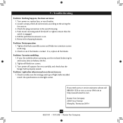
...; Hunter Fan Company Push motor reversing switch firmly left or right to see if the blade is properly seated. Problem: Excessive wobbling. 1. If your fan wobbles when operating, use the enclosed balancing kit and instructions to ensure it is engaged. 5. If so, replace all blade iron screws. 3. Problem: Lights dim when turned on or do not turn on , replace fuse, or reset breaker. 2. Pull the pull chain to balance the fan. 2. Tighten the blade assembly screws and blade iron armature screws...
...; Hunter Fan Company Push motor reversing switch firmly left or right to see if the blade is properly seated. Problem: Excessive wobbling. 1. If your fan wobbles when operating, use the enclosed balancing kit and instructions to ensure it is engaged. 5. If so, replace all blade iron screws. 3. Problem: Lights dim when turned on or do not turn on , replace fuse, or reset breaker. 2. Pull the pull chain to balance the fan. 2. Tighten the blade assembly screws and blade iron armature screws...
Parts Guide
Page 1
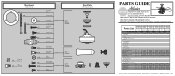
...Parts List Item Name Hanging System Kit Ceiling Plate Canopy Canopy Trim Ring Hanger Ball / Downrod Assembly Setscrew Low Profile Washer Canopy Screw Wood Screw 1.5" Wood Screw 3" Flat Washer Mounting Isolator Screw, Low Profile Switch Housing, Alternate Blade Iron Set Blade Set Screw, Blade Iron Armature Hardware Kit Blade Grommet Blade Assembly Screw Screw, Machine, 6-32 Wire Connector Screw, Switch Housing Assembly Balancing Kit Light Kit Assembly Thumb Screw Light bulb / Bulb Globe/Shade Model # Asm. Hardware (Drawn to Scale) x 1 x 2 x 4 x 2 x 3 x 4 x 1 x 4 Balancing x 1 Kit Wire...
...Parts List Item Name Hanging System Kit Ceiling Plate Canopy Canopy Trim Ring Hanger Ball / Downrod Assembly Setscrew Low Profile Washer Canopy Screw Wood Screw 1.5" Wood Screw 3" Flat Washer Mounting Isolator Screw, Low Profile Switch Housing, Alternate Blade Iron Set Blade Set Screw, Blade Iron Armature Hardware Kit Blade Grommet Blade Assembly Screw Screw, Machine, 6-32 Wire Connector Screw, Switch Housing Assembly Balancing Kit Light Kit Assembly Thumb Screw Light bulb / Bulb Globe/Shade Model # Asm. Hardware (Drawn to Scale) x 1 x 2 x 4 x 2 x 3 x 4 x 1 x 4 Balancing x 1 Kit Wire...


