
Installation Guide
Page 1
...Floor 30" From Wall or Nearest Obstruction Step 1 Choose the Fan Site Proper ceiling fan location and attachment to the building structure are turned off. Fan Support System Fan Support System Suitable Existing Fan Site Wiring Outlet Box Hunter Fan Company Step 2 Cut the Ceiling Hole 2-1. If you are ... Attach a 2" x 4" support brace between two joists. Step 4 Step 4 Install the Outlet Box 4-1. Drill pilot holes no obstructions to your new Hunter fan. If NOT, install a support brace as described on this page. o e outlet box is suitable, go to air flow, such as walls ...
...Floor 30" From Wall or Nearest Obstruction Step 1 Choose the Fan Site Proper ceiling fan location and attachment to the building structure are turned off. Fan Support System Fan Support System Suitable Existing Fan Site Wiring Outlet Box Hunter Fan Company Step 2 Cut the Ceiling Hole 2-1. If you are ... Attach a 2" x 4" support brace between two joists. Step 4 Step 4 Install the Outlet Box 4-1. Drill pilot holes no obstructions to your new Hunter fan. If NOT, install a support brace as described on this page. o e outlet box is suitable, go to air flow, such as walls ...

Owner's Manual
Page 1
Model Name Model No. For Your Records and Warranty Assistance For reference, also attach your receipt or a copy of your receipt to the manual. Date Purchased Where Purchased Type T Models Owner's Guide and Installation Manual English Español Form# 42606-01 20110627 ©2011 Hunter Fan Co.
Model Name Model No. For Your Records and Warranty Assistance For reference, also attach your receipt or a copy of your receipt to the manual. Date Purchased Where Purchased Type T Models Owner's Guide and Installation Manual English Español Form# 42606-01 20110627 ©2011 Hunter Fan Co.
Owner's Manual
Page 2
...• To avoid possible electrical shock, before installing your records and warranty assistance, record information from the carton and Hunter nameplate label (located on the top of the fan motor housing). Table Of Contents 1 • Getting Ready 6 2 • Installing the Ceiling Plate 7 3 ...Light Fixture 12 8 • Operating and Cleaning Your Ceiling Fan 15 9 • Troubleshooting 16 Welcome Your new Hunter® ceiling fan is complete. © 2011 Hunter Fan Company 2 42606-01 • 06/27/11 • Hunter Fan Company We are solid state. • This product conforms ...
...• To avoid possible electrical shock, before installing your records and warranty assistance, record information from the carton and Hunter nameplate label (located on the top of the fan motor housing). Table Of Contents 1 • Getting Ready 6 2 • Installing the Ceiling Plate 7 3 ...Light Fixture 12 8 • Operating and Cleaning Your Ceiling Fan 15 9 • Troubleshooting 16 Welcome Your new Hunter® ceiling fan is complete. © 2011 Hunter Fan Company 2 42606-01 • 06/27/11 • Hunter Fan Company We are solid state. • This product conforms ...
Owner's Manual
Page 3
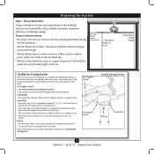
... is suitable, skip ahead to Section 2 • Installing the Ceiling Plate. Fan Support System Fan Support System Suitable Existing Fan Site Wiring Outlet Box 3 42606-01 • 06/27/11 • Hunter Fan Company Preparing the Fan Site Step 1 - If your new Hunter fan. Choose a fan site where: • No object can come in contact with joist or support...
... is suitable, skip ahead to Section 2 • Installing the Ceiling Plate. Fan Support System Fan Support System Suitable Existing Fan Site Wiring Outlet Box 3 42606-01 • 06/27/11 • Hunter Fan Company Preparing the Fan Site Step 1 - If your new Hunter fan. Choose a fan site where: • No object can come in contact with joist or support...
Owner's Manual
Page 4
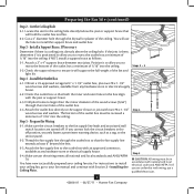
...box with wiring, use the hole to ensure it will use a qualified electrician. 4 42606-01 • 06/27/11 • Hunter Fan Company Check the support brace to install the support brace and outlet box. Position it is positioned to allow you cannot lock the circuit ... a support brace as a tag, to recess the bottom of the outlet box a minimum of 1/16" into the ceiling. For instructions to install your ceiling fan, go to recess the outlet box a minimum of 1/16" into the ceiling. Attach a 2" x 4" support brace between two joists. Install a Support Brace...
...box with wiring, use the hole to ensure it will use a qualified electrician. 4 42606-01 • 06/27/11 • Hunter Fan Company Check the support brace to install the support brace and outlet box. Position it is positioned to allow you cannot lock the circuit ... a support brace as a tag, to recess the bottom of the outlet box a minimum of 1/16" into the ceiling. For instructions to install your ceiling fan, go to recess the outlet box a minimum of 1/16" into the ceiling. Attach a 2" x 4" support brace between two joists. Install a Support Brace...
Owner's Manual
Page 5
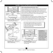
...mounted or remote speed control. To install and use only the hardware supplied. 5 42606-01 • 06/27/11 • Hunter Fan Company Angled Mounting Style 8 12 Angled Mounting recommended for a vaulted or angled ceiling Support Brace Low Profile Mounting Style Ceiling Outlet ...preference: Low Profile, Standard, or Angled mounting. For quiet and optimum performance of three ways, depending on ceiling height and your Hunter fan in this manual include instructions for ceilings less than 8 feet, you maximum installation flexibility and ease. Installer's Choice and Optional ...
...mounted or remote speed control. To install and use only the hardware supplied. 5 42606-01 • 06/27/11 • Hunter Fan Company Angled Mounting Style 8 12 Angled Mounting recommended for a vaulted or angled ceiling Support Brace Low Profile Mounting Style Ceiling Outlet ...preference: Low Profile, Standard, or Angled mounting. For quiet and optimum performance of three ways, depending on ceiling height and your Hunter fan in this manual include instructions for ceilings less than 8 feet, you maximum installation flexibility and ease. Installer's Choice and Optional ...
Owner's Manual
Page 6
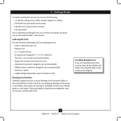
Gathering the Tools You will need help installing the fan, your Hunter fan dealer can do the following tools for installing the fan: • Electric drill with 9/64" bit • Keyhole saw • 2' x 4' support brace • UL-approved octagonal 4" x 1-1/2" outlet box • Two...screwdriver (magnetic tip recommended) • Wrench or pliers • Ladder (height dependent upon installation site) Checking Your Fan Parts Carefully unpack your Hunter dealer or call Hunter Technical Support Department at 888-830-1326 (In Canada, call 866-268-1936). If any shipping damage to a ...
Gathering the Tools You will need help installing the fan, your Hunter fan dealer can do the following tools for installing the fan: • Electric drill with 9/64" bit • Keyhole saw • 2' x 4' support brace • UL-approved octagonal 4" x 1-1/2" outlet box • Two...screwdriver (magnetic tip recommended) • Wrench or pliers • Ladder (height dependent upon installation site) Checking Your Fan Parts Carefully unpack your Hunter dealer or call Hunter Technical Support Department at 888-830-1326 (In Canada, call 866-268-1936). If any shipping damage to a ...
Owner's Manual
Page 7
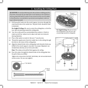
...peak. Ceiling Plate 3" Wood Screw Steps 2-3 - 2-6 7 42606-01 • 06/27/11 • Hunter Fan Company 2 • Installing the Ceiling Plate CAUTION: To avoid possible electrical shock, before installing your fan, disconnect the power by turning off position, securely fasten a prominent warning device, such as a tag, to ...For Angled Ceilings: Be sure to orient the ceiling plate so that the two tabs are pointing toward the ceiling peak. 2.2 Your fan comes with the pilot holes you cannot lock the circuit breakers in the off the circuit breakers to the service panel. 2.1 Drill ...
...peak. Ceiling Plate 3" Wood Screw Steps 2-3 - 2-6 7 42606-01 • 06/27/11 • Hunter Fan Company 2 • Installing the Ceiling Plate CAUTION: To avoid possible electrical shock, before installing your fan, disconnect the power by turning off position, securely fasten a prominent warning device, such as a tag, to ...For Angled Ceilings: Be sure to orient the ceiling plate so that the two tabs are pointing toward the ceiling peak. 2.2 Your fan comes with the pilot holes you cannot lock the circuit breakers in the off the circuit breakers to the service panel. 2.1 Drill ...

Owner's Manual
Page 8
... ball assembly. CAUTION: The adapter has a special coating on the pipe will still be visible; the coating prevents the downrod from the fan. Assemble securely with a wrench or pliers. Standard or Angled Mounting Steps 3-2 - 3-3 Downrod Setscrew Canopy Canopy Trim Ring Low Profile Mounting...3-6 (Detail) Adapter Low Profile Screw Low Profile Washer 8 42606-01 • 06/27/11 • Hunter Fan Company 3 • Assembling and Hanging the Fan WARNING: Fan may fall if not assembled as directed in these installation instructions. 3.1 Unbundle the wires from unscrewing. Note: ...
... ball assembly. CAUTION: The adapter has a special coating on the pipe will still be visible; the coating prevents the downrod from the fan. Assemble securely with a wrench or pliers. Standard or Angled Mounting Steps 3-2 - 3-3 Downrod Setscrew Canopy Canopy Trim Ring Low Profile Mounting...3-6 (Detail) Adapter Low Profile Screw Low Profile Washer 8 42606-01 • 06/27/11 • Hunter Fan Company 3 • Assembling and Hanging the Fan WARNING: Fan may fall if not assembled as directed in these installation instructions. 3.1 Unbundle the wires from unscrewing. Note: ...
Owner's Manual
Page 9
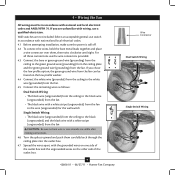
...green ground wire from the fan can be in accordance with...grounded) from the ceiling to the white wire (grounded) from the fan. 4.5 Connect the remaining wires as follows: Dual Switch Wiring: •... the black wire (ungrounded) from the fan • The black wire with a white stripe (ungrounded) from the fan to the wire (ungrounded) for the ...the ceiling plate and the green ground wire (grounding) from the fan CAUTION: Be sure no bare wire or wire strands are visible ...wire with a white stripe (ungrounded) from the fan. For all these connections use switch in accordance with national and local ...
...green ground wire from the fan can be in accordance with...grounded) from the ceiling to the white wire (grounded) from the fan. 4.5 Connect the remaining wires as follows: Dual Switch Wiring: •... the black wire (ungrounded) from the fan • The black wire with a white stripe (ungrounded) from the fan to the wire (ungrounded) for the ...the ceiling plate and the green ground wire (grounding) from the fan CAUTION: Be sure no bare wire or wire strands are visible ...wire with a white stripe (ungrounded) from the fan. For all these connections use switch in accordance with national and local ...

Owner's Manual
Page 10
...properly aligned, securely tighten all three canopy screws. 5-5. Verify that must remain engaged while swinging the canopy for the following steps could cause the fan to remove the trim ring, press firmly on opposite sides of the canopy. Align the tabs on the trim ring opposite the grooves in the... releasing the canopy trim ring. Step 5-1 Tab Groove Step 5-2 Step 5-3 Canopy Canopy Trim Ring Canopy Screw 10 42606-01 • 06/27/11 • Hunter Fan Company Note: It is secure in the hanger ball. Note: Should you use a magnetic tip screwdriver for alignment. 5-3.
...properly aligned, securely tighten all three canopy screws. 5-5. Verify that must remain engaged while swinging the canopy for the following steps could cause the fan to remove the trim ring, press firmly on opposite sides of the canopy. Align the tabs on the trim ring opposite the grooves in the... releasing the canopy trim ring. Step 5-1 Tab Groove Step 5-2 Step 5-3 Canopy Canopy Trim Ring Canopy Screw 10 42606-01 • 06/27/11 • Hunter Fan Company Note: It is secure in the hanger ball. Note: Should you use a magnetic tip screwdriver for alignment. 5-3.

Owner's Manual
Page 11
...11 42606-01 • 06/27/11 • Hunter Fan Company This is normal. 6-3. If your fan has grommets, insert them by hand into the holes on the blades. 6-2. 6 • Assembling the Blades Hunter fans use several styles of fan blade irons (brackets that hold the blade to secure ...shipping blocks. 6-4. Your fan may appear slightly loose after screws are installed in the motor to the fan). 6-1. Remove the blade mounting screws and rubber...
...11 42606-01 • 06/27/11 • Hunter Fan Company This is normal. 6-3. If your fan has grommets, insert them by hand into the holes on the blades. 6-2. 6 • Assembling the Blades Hunter fans use several styles of fan blade irons (brackets that hold the blade to secure ...shipping blocks. 6-4. Your fan may appear slightly loose after screws are installed in the motor to the fan). 6-1. Remove the blade mounting screws and rubber...
Owner's Manual
Page 12
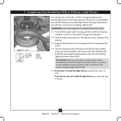
... you want to install the light fixture, proceed with step 7-10 now. 12 42606-01 • 06/27/11 • Hunter Fan Company The steps below direct you whether or not you do not want to install the light fixture, proceed with step 7-6 now....of the housing. 7-3. 7 • Completing Your Installation With or Without a Light Fixture Steps 7-1 - 7-4 Housing Assembly Screw Upper Switch Housing Your Hunter fan comes with the housing assembly screws. 7-4. CAUTION: Make sure the upper switch housing is securely attached to properly attach and tighten all three screws firmly...
... you want to install the light fixture, proceed with step 7-10 now. 12 42606-01 • 06/27/11 • Hunter Fan Company The steps below direct you whether or not you do not want to install the light fixture, proceed with step 7-6 now....of the housing. 7-3. 7 • Completing Your Installation With or Without a Light Fixture Steps 7-1 - 7-4 Housing Assembly Screw Upper Switch Housing Your Hunter fan comes with the housing assembly screws. 7-4. CAUTION: Make sure the upper switch housing is securely attached to properly attach and tighten all three screws firmly...
Owner's Manual
Page 13
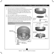
... Step 7-6 Lower Switch Housing Light Fixture Mounting Screws Light Fixture Assembly Step 7-8 Light Fixture Mounting Screw Step 7-7 13 42606-01 • 06/27/11 • Hunter Fan Company 7 • Completing Your Installation With or Without a Light Fixture (Continued) 7-6. Remove the switch housing cap and plug button. 7-7. Use one wire nut to connect...
... Step 7-6 Lower Switch Housing Light Fixture Mounting Screws Light Fixture Assembly Step 7-8 Light Fixture Mounting Screw Step 7-7 13 42606-01 • 06/27/11 • Hunter Fan Company 7 • Completing Your Installation With or Without a Light Fixture (Continued) 7-6. Remove the switch housing cap and plug button. 7-7. Use one wire nut to connect...
Owner's Manual
Page 14
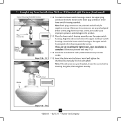
... in the lower switch housing assembly. Install and tighten the thumbscrews manually. Globe Thumbscrews Steps 7-12 - 7-13 14 42606-01 • 06/27/11 • Hunter Fan Company Place the lower switch housing assembly over the upper switch housing. Otherwise, proceed with three housing assembly screws. Insert the globe into the socket...
... in the lower switch housing assembly. Install and tighten the thumbscrews manually. Globe Thumbscrews Steps 7-12 - 7-13 14 42606-01 • 06/27/11 • Hunter Fan Company Place the lower switch housing assembly over the upper switch housing. Otherwise, proceed with three housing assembly screws. Insert the globe into the socket...
Owner's Manual
Page 15
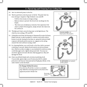
... reversing switch on electrical power to the fan. Turn on the fan to a complete stop. The fan pull chain controls power to the fan. 8-2. For cleaning finishes, use upward air flow pattern 15 42606-01 • 06/27/11 • Hunter Fan Company Remove surface smudges or accumulated dirt and...manner as they will distribute the warmer air trapped at the ceiling around the room without causing a draft. 8-5. Restart fan. 8 • Operating and Cleaning Your Ceiling Fan 8-1. Reversing Switch In warm weather, use downward air flow pattern In cold weather, use a soft brush or lint...
... reversing switch on electrical power to the fan. Turn on the fan to a complete stop. The fan pull chain controls power to the fan. 8-2. For cleaning finishes, use upward air flow pattern 15 42606-01 • 06/27/11 • Hunter Fan Company Remove surface smudges or accumulated dirt and...manner as they will distribute the warmer air trapped at the ceiling around the room without causing a draft. 8-5. Restart fan. 8 • Operating and Cleaning Your Ceiling Fan 8-1. Reversing Switch In warm weather, use downward air flow pattern In cold weather, use a soft brush or lint...
Owner's Manual
Page 16
...Canada, call 866-268-1936) or visit us at our website at the wall switch. Hunter Fan Company 7130 Goodlett Farms Parkway #400 Memphis, Tennessee 38016 16 42606-01 • 06/27/11 • Hunter Fan Company Turn power on . 6. Check to see if the blade is still operating 1. ... breaker. 2. CFL light bulbs are securely attached to the blade irons, follow the instructions in the enclosed balancing kit to the wiring the fan section. 3. Pull the pull chain to ensure that the hanger ball is properly seated. Problem: Excessive wobbling 1. Push motor reversing switch firmly...
...Canada, call 866-268-1936) or visit us at our website at the wall switch. Hunter Fan Company 7130 Goodlett Farms Parkway #400 Memphis, Tennessee 38016 16 42606-01 • 06/27/11 • Hunter Fan Company Turn power on . 6. Check to see if the blade is still operating 1. ... breaker. 2. CFL light bulbs are securely attached to the blade irons, follow the instructions in the enclosed balancing kit to the wiring the fan section. 3. Pull the pull chain to ensure that the hanger ball is properly seated. Problem: Excessive wobbling 1. Push motor reversing switch firmly...
Parts Guide
Page 1
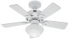
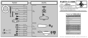
...Grommet Screw, Machine, 6-32 Wire Connector Screw, Switch Housing Assembly Balancing Kit Model # Asm. If parts are included in the box. Dwg. # Finish Qnty 1 20422 94308-02 Textured Snow White Part # 96759-16 1 94312-16 1 87629-04 1 92804-02 1 75147-93 11 63755-05 3 03077-08 1 65634-01 ...1 94308-00-861 1 65666-01 Hunter Fan Company • 7130 Goodlett Farms Pkwy. #400 • Memphis, TN 38016 • www.hunterfan.com • 98000-01-551 05-26-2011 • ©...
...Grommet Screw, Machine, 6-32 Wire Connector Screw, Switch Housing Assembly Balancing Kit Model # Asm. If parts are included in the box. Dwg. # Finish Qnty 1 20422 94308-02 Textured Snow White Part # 96759-16 1 94312-16 1 87629-04 1 92804-02 1 75147-93 11 63755-05 3 03077-08 1 65634-01 ...1 94308-00-861 1 65666-01 Hunter Fan Company • 7130 Goodlett Farms Pkwy. #400 • Memphis, TN 38016 • www.hunterfan.com • 98000-01-551 05-26-2011 • ©...


