
Installation Guide
Page 1
... octagonal 4" x 1-1/2" outlet box • Two #8 x 1-1/2" wood screws and washers • Approved connector for electrical wire Checklist for safety, reliable operation, maximum efficiency, and energy savings. o e bottom of the outlet box is directly below a joist or support brace that the fan supply line extends at any hardware store or electrical supply house. 4-2. Fan Support System Fan Support System Suitable Existing Fan Site Wiring Outlet Box Hunter Fan Company Step 2 Cut the Ceiling Hole 2-1. If the...
... octagonal 4" x 1-1/2" outlet box • Two #8 x 1-1/2" wood screws and washers • Approved connector for electrical wire Checklist for safety, reliable operation, maximum efficiency, and energy savings. o e bottom of the outlet box is directly below a joist or support brace that the fan supply line extends at any hardware store or electrical supply house. 4-2. Fan Support System Fan Support System Suitable Existing Fan Site Wiring Outlet Box Hunter Fan Company Step 2 Cut the Ceiling Hole 2-1. If the...

Owner's Manual
Page 1
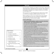
Date Purchased Where Purchased Type T Models Owner's Guide and Installation Manual English Español Form# 42606-01 20110627 ©2011 Hunter Fan Co. Model Name Model No. For Your Records and Warranty Assistance For reference, also attach your receipt or a copy of your receipt to the manual.
Date Purchased Where Purchased Type T Models Owner's Guide and Installation Manual English Español Form# 42606-01 20110627 ©2011 Hunter Fan Co. Model Name Model No. For Your Records and Warranty Assistance For reference, also attach your receipt or a copy of your receipt to the manual.
Owner's Manual
Page 2
... our work. Use only Hunter speed controls, which are proud of the fan motor housing). SAVE THESE INSTRUCTIONS. • Use only Hunter replacement parts. • To reduce the risk of personal injury, attach the fan directly to the service panel. • All wiring must be in accordance with the best ceiling fan available anywhere in the off the circuit breakers to your fan. This installation and operation manual gives you with national and local electrical codes...
... our work. Use only Hunter speed controls, which are proud of the fan motor housing). SAVE THESE INSTRUCTIONS. • Use only Hunter replacement parts. • To reduce the risk of personal injury, attach the fan directly to the service panel. • All wiring must be in accordance with the best ceiling fan available anywhere in the off the circuit breakers to your fan. This installation and operation manual gives you with national and local electrical codes...
Owner's Manual
Page 3
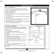
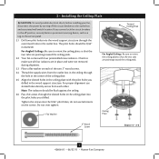
... Section 2 • Installing the Ceiling Plate. Fan Support System Fan Support System Suitable Existing Fan Site Wiring Outlet Box 3 42606-01 • 06/27/11 • Hunter Fan Company Fan Support System • Fan attaches directly to the joist or support brace by wood screws and washers through the inner holes of outlet box. • The outer holes of the outlet box are aligned with the rotating fan blades during normal operation. • The fan blades are essential for...
... Section 2 • Installing the Ceiling Plate. Fan Support System Fan Support System Suitable Existing Fan Site Wiring Outlet Box 3 42606-01 • 06/27/11 • Hunter Fan Company Fan Support System • Fan attaches directly to the joist or support brace by wood screws and washers through the inner holes of outlet box. • The outer holes of the outlet box are aligned with the rotating fan blades during normal operation. • The fan blades are essential for...
Owner's Manual
Page 4
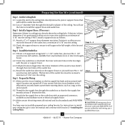
... box, plus two #8 x 1-1/2" wood screws and washers, available from any hardware store or electrical supply house. 5-4. Prepare the Wiring 5-1. If you to the fan supply line leads and associated wall switch location are unfamiliar with an approved connector, available at least 6" beyond the box. 5-3. Thread the fan supply line through the inner holes of the ceiling. Preparing the Fan Site (continued) Step 2 - Locate the site for the ceiling hole directly...
... box, plus two #8 x 1-1/2" wood screws and washers, available from any hardware store or electrical supply house. 5-4. Prepare the Wiring 5-1. If you to the fan supply line leads and associated wall switch location are unfamiliar with an approved connector, available at least 6" beyond the box. 5-3. Thread the fan supply line through the inner holes of the ceiling. Preparing the Fan Site (continued) Step 2 - Locate the site for the ceiling hole directly...
Owner's Manual
Page 5
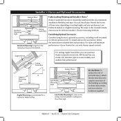
... ease. For quiet and optimum performance of your preference: Low Profile, Standard, or Angled mounting. Installer's Choice and Optional Accessories Support Brace Standard Mounting Style Ceiling Outlet Box Standard Mounting hangs from the ceiling by a downrod (included). All Hunter fans use the accessories, follow the instructions included with each product. Considering Optional Accessories Consider using Hunter's optional accessories, including a wall-mounted or remote speed control. You can purchase Hunter extension downrods. The steps in one of the building according to...
... ease. For quiet and optimum performance of your preference: Low Profile, Standard, or Angled mounting. Installer's Choice and Optional Accessories Support Brace Standard Mounting Style Ceiling Outlet Box Standard Mounting hangs from the ceiling by a downrod (included). All Hunter fans use the accessories, follow the instructions included with each product. Considering Optional Accessories Consider using Hunter's optional accessories, including a wall-mounted or remote speed control. You can purchase Hunter extension downrods. The steps in one of the building according to...
Owner's Manual
Page 6
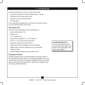
... the fan parts. Installing Multiple Fans? If you need the following tools for installing the fan: • Electric drill with 9/64" bit • Keyhole saw • 2' x 4' support brace • UL-approved octagonal 4" x 1-1/2" outlet box • Two #8 x 1-1/2" wood screws and washers • Approved connector for and install wood screws. • Identify and connect electrical wires. • Lift 40 pounds. If any shipping damage to the included Parts Guide. Refer to the motor or fan blades.
... the fan parts. Installing Multiple Fans? If you need the following tools for installing the fan: • Electric drill with 9/64" bit • Keyhole saw • 2' x 4' support brace • UL-approved octagonal 4" x 1-1/2" outlet box • Two #8 x 1-1/2" wood screws and washers • Approved connector for and install wood screws. • Identify and connect electrical wires. • Lift 40 pounds. If any shipping damage to the included Parts Guide. Refer to the motor or fan blades.
Owner's Manual
Page 7
... service panel. 2.1 Drill two pilot holes into the wood support structure through the slotted holes in the ceiling plate into the 9/64" pilot holes; do not use slotted holes directly across from the outlet box in the ceiling through the hole in the center of the two 3" wood screws. 2.4 Thread the supply wires from each of the ceiling plate. 2.5 Align the slotted holes in the ceiling plate with four preinstalled noise isolators...
... service panel. 2.1 Drill two pilot holes into the wood support structure through the slotted holes in the ceiling plate into the 9/64" pilot holes; do not use slotted holes directly across from the outlet box in the ceiling through the hole in the center of the two 3" wood screws. 2.4 Thread the supply wires from each of the ceiling plate. 2.5 Align the slotted holes in the ceiling plate with four preinstalled noise isolators...

Owner's Manual
Page 8
... on the adapter to install the pipe and ball assembly. Assemble securely with a wrench or pliers. Securely retighten the setscrew with three low profile screws. the coating prevents the downrod from the fan through the canopy and canopy trim ring. Standard or Angled Mounting Steps 3-2 - 3-3 Downrod Setscrew Canopy Canopy Trim Ring Low Profile Mounting Steps 3-5 - 3-6 Low Profile Screws Green Ground Wire Canopy Trim Ring Low Profile Washer Canopy Low Profile Screw Step 3-6 (Detail) Adapter Low Profile Screw Low Profile Washer 8 42606-01 • 06/27/11 • Hunter Fan Company...
... on the adapter to install the pipe and ball assembly. Assemble securely with a wrench or pliers. Securely retighten the setscrew with three low profile screws. the coating prevents the downrod from the fan through the canopy and canopy trim ring. Standard or Angled Mounting Steps 3-2 - 3-3 Downrod Setscrew Canopy Canopy Trim Ring Low Profile Mounting Steps 3-5 - 3-6 Low Profile Screws Green Ground Wire Canopy Trim Ring Low Profile Washer Canopy Low Profile Screw Step 3-6 (Detail) Adapter Low Profile Screw Low Profile Washer 8 42606-01 • 06/27/11 • Hunter Fan Company...
Owner's Manual
Page 9
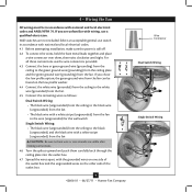
...; 06/27/11 • Hunter Fan Company Wire Connector Dual Switch Wiring Single Switch Wiring Wall switches are unfamiliar with national and local electrical codes. 4.1 Before attempting installation, make sure the power is still off. 4.2 To connect the wires, hold the bare metal leads together and place a wire connector over them carefully back through the ceiling plate into the outlet box. 4.7 Spread the wires apart, with national and local electrical codes and ANSI/NFPA 70. If...
...; 06/27/11 • Hunter Fan Company Wire Connector Dual Switch Wiring Single Switch Wiring Wall switches are unfamiliar with national and local electrical codes. 4.1 Before attempting installation, make sure the power is still off. 4.2 To connect the wires, hold the bare metal leads together and place a wire connector over them carefully back through the ceiling plate into the outlet box. 4.7 Spread the wires apart, with national and local electrical codes and ANSI/NFPA 70. If...

Owner's Manual
Page 10
... canopy screws. 5-5. The canopy trim ring will flex out releasing the canopy trim ring. Verify that must remain engaged while swinging the canopy for the following steps could cause the fan to remove the trim ring, press firmly on the trim ring opposite the grooves in the hanger ball groove. Step 5-1 Tab Groove Step 5-2 Step 5-3 Canopy Canopy Trim Ring Canopy Screw 10 42606-01 • 06/27/11 • Hunter Fan Company 5 • Installing the Canopy and Canopy Trim Ring...
... canopy screws. 5-5. The canopy trim ring will flex out releasing the canopy trim ring. Verify that must remain engaged while swinging the canopy for the following steps could cause the fan to remove the trim ring, press firmly on the trim ring opposite the grooves in the hanger ball groove. Step 5-1 Tab Groove Step 5-2 Step 5-3 Canopy Canopy Trim Ring Canopy Screw 10 42606-01 • 06/27/11 • Hunter Fan Company 5 • Installing the Canopy and Canopy Trim Ring...

Owner's Manual
Page 11
... blades. 6-2. For each blade to the fan. Remove the blade mounting screws and rubber shipping bumpers from the motor. Attach each blade, insert one blade mounting screw through the blade iron, and attach lightly to a blade iron using three blade assembly screws. Step 6-1 (Detail) Grommet Use with grommet Blade Assembly Screws Steps 6-1 - 6-2 Use without grommet Blade Mounting Screw Step 6-4 11 42606-01 • 06/27/11 • Hunter Fan Company Your fan may appear slightly loose after screws are installed in the motor to the fan). 6-1. Note: Some blade mounting screws...
... blades. 6-2. For each blade to the fan. Remove the blade mounting screws and rubber shipping bumpers from the motor. Attach each blade, insert one blade mounting screw through the blade iron, and attach lightly to a blade iron using three blade assembly screws. Step 6-1 (Detail) Grommet Use with grommet Blade Assembly Screws Steps 6-1 - 6-2 Use without grommet Blade Mounting Screw Step 6-4 11 42606-01 • 06/27/11 • Hunter Fan Company Your fan may appear slightly loose after screws are installed in the motor to the fan). 6-1. Note: Some blade mounting screws...
Owner's Manual
Page 12
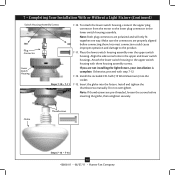
... • Hunter Fan Company Turn the housing counterclockwise until the housing assembly screws are installing a light fixture. If you do not want to properly attach and tighten all three screws firmly. If you want to the switch housing mounting plate. Align the keyhole slots in the housing with this fan model. 7-1. Install the remaining housing assembly screw into the switch housing mounting plate. 7-2. To attach the upper switch housing, partially install two housing assembly screws into the housing. Feed the upper plug connector through the...
... • Hunter Fan Company Turn the housing counterclockwise until the housing assembly screws are installing a light fixture. If you do not want to properly attach and tighten all three screws firmly. If you want to the switch housing mounting plate. Align the keyhole slots in the housing with this fan model. 7-1. Install the remaining housing assembly screw into the switch housing mounting plate. 7-2. To attach the upper switch housing, partially install two housing assembly screws into the housing. Feed the upper plug connector through the...
Owner's Manual
Page 13
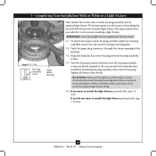
... black wire from the light fixture to the black/white wire from the light fixture through the hole in the bottom on the lower switch housing. Remove the switch housing cap and plug button. 7-7. Insert and tighten two light fixture mounting screws. 7-9. CAUTION: Be sure no bare wire or wire strands are visible after making connections. Switch Housing Cap Nut Washer Lower Switch Housing Plug Button Step 7-6 Lower Switch Housing Light Fixture Mounting Screws Light Fixture Assembly Step 7-8 Light Fixture Mounting Screw Step 7-7 13 42606-01 • 06/27/11 • Hunter Fan Company...
... black wire from the light fixture to the black/white wire from the light fixture through the hole in the bottom on the lower switch housing. Remove the switch housing cap and plug button. 7-7. Insert and tighten two light fixture mounting screws. 7-9. CAUTION: Be sure no bare wire or wire strands are visible after making connections. Switch Housing Cap Nut Washer Lower Switch Housing Plug Button Step 7-6 Lower Switch Housing Light Fixture Mounting Screws Light Fixture Assembly Step 7-8 Light Fixture Mounting Screw Step 7-7 13 42606-01 • 06/27/11 • Hunter Fan Company...
Owner's Manual
Page 14
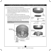
...; 06/27/11 • Hunter Fan Company Install and tighten the thumbscrews manually. Incorrect connection could cause improper operation and damage to the lower plug connector in the upper and lower switch housings. Attach the lower switch housing to the upper switch housing with step 7-12. 7-12. Insert the globe into the socket. 7-13. Align the side screw holes in the lower switch housing assembly. 7 • Completing Your Installation With or Without a Light Fixture (Continued) Switch Housing Assembly Screws Plug Connector Lower Switch Housing Steps 7-10 - 7-11...
...; 06/27/11 • Hunter Fan Company Install and tighten the thumbscrews manually. Incorrect connection could cause improper operation and damage to the lower plug connector in the upper and lower switch housings. Attach the lower switch housing to the upper switch housing with step 7-12. 7-12. Insert the globe into the socket. 7-13. Align the side screw holes in the lower switch housing assembly. 7 • Completing Your Installation With or Without a Light Fixture (Continued) Switch Housing Assembly Screws Plug Connector Lower Switch Housing Steps 7-10 - 7-11...
Owner's Manual
Page 15
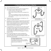
... change settings. • Release slowly to the fan. 8-2. To Change Airflow Direction Turn the fan off and let it come to the fan. 8 • Operating and Cleaning Your Ceiling Fan 8-1. The fan pull chain controls power to a complete stop. If this happens, simply reinsert the chain into the blades. • The chain uses a breakaway connector that separates if the chain is jerked. The chain has two settings: ON and OFF. 8-4. Reversing Switch In warm weather, use downward air...
... change settings. • Release slowly to the fan. 8-2. To Change Airflow Direction Turn the fan off and let it come to the fan. 8 • Operating and Cleaning Your Ceiling Fan 8-1. The fan pull chain controls power to a complete stop. If this happens, simply reinsert the chain into the blades. • The chain uses a breakaway connector that separates if the chain is jerked. The chain has two settings: ON and OFF. 8-4. Reversing Switch In warm weather, use downward air...
Owner's Manual
Page 16
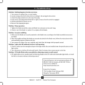
... blade assembly screws and blade iron armature screws until snug. 2. Problem: Noisy operation 1. After thoroughly verifying the blades are installed meet the specifications on , replace fuse, or reset breaker. 2. Check the plug connection in a location without a dimming control. Check to make sure the wattage and type of the light bulbs that the switch is cracked. 9 • Troubleshooting Problem: Nothing happens; Push motor reversing switch firmly left or right to the fan. Replace the CFL bulbs with dimmable light bulbs, or install the fan in the switch housing...
... blade assembly screws and blade iron armature screws until snug. 2. Problem: Noisy operation 1. After thoroughly verifying the blades are installed meet the specifications on , replace fuse, or reset breaker. 2. Check the plug connection in a location without a dimming control. Check to make sure the wattage and type of the light bulbs that the switch is cracked. 9 • Troubleshooting Problem: Nothing happens; Push motor reversing switch firmly left or right to the fan. Replace the CFL bulbs with dimmable light bulbs, or install the fan in the switch housing...
Parts Guide
Page 1
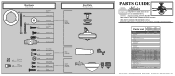
... PARTS GUIDE Using this Parts Guide, make sure all parts are missing, DO NOT RETURN THIS ITEM TO THE STORE, call 888-830-1326 for assistance. Parts List Item Name * Hanging System Kit Ceiling Plate Canopy Canopy Trim Ring Hanger Ball / Downrod Assembly Setscrew Low Profile Washer Canopy Screw Wood Screw Wood Screw Flat Washer Mounting Isolator * Screw, Low Profile Switch Housing Assembly Light Kit Assembly Blade Iron Set Blade Set Screw, Blade Iron Armature Thumb Screw CFL Bulb Hardware Kit Blade Assembly Screw Blade Grommet Screw, Machine, 6-32 Wire Connector Screw, Switch Housing Assembly...
... PARTS GUIDE Using this Parts Guide, make sure all parts are missing, DO NOT RETURN THIS ITEM TO THE STORE, call 888-830-1326 for assistance. Parts List Item Name * Hanging System Kit Ceiling Plate Canopy Canopy Trim Ring Hanger Ball / Downrod Assembly Setscrew Low Profile Washer Canopy Screw Wood Screw Wood Screw Flat Washer Mounting Isolator * Screw, Low Profile Switch Housing Assembly Light Kit Assembly Blade Iron Set Blade Set Screw, Blade Iron Armature Thumb Screw CFL Bulb Hardware Kit Blade Assembly Screw Blade Grommet Screw, Machine, 6-32 Wire Connector Screw, Switch Housing Assembly...


