
Owner's Manual
Page 1
Model Name Model No. Date Purchased Where Purchased Type 2 Models Owner's Guide and Installation Manual English Español Form# 42676-01 20110404 ©2011 Hunter Fan Co. For Your Records and Warranty Assistance For reference, also attach your receipt or a copy of your receipt to the manual.
Model Name Model No. Date Purchased Where Purchased Type 2 Models Owner's Guide and Installation Manual English Español Form# 42676-01 20110404 ©2011 Hunter Fan Co. For Your Records and Warranty Assistance For reference, also attach your receipt or a copy of your receipt to the manual.
Owner's Manual
Page 2
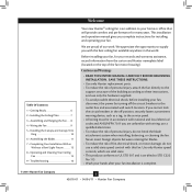
...8226; READ THIS ENTIRE MANUAL CAREFULLY BEFORE BEGINNING INSTALLATION. SAVE THESE INSTRUCTIONS. • Use only Hunter replacement parts. • To reduce the risk of personal injury, attach the fan directly to the support structure of fire, electrical shock, or motor damage, do not bend the ...the Blades 11 7 • Completing Your Installation With or Without a Bowl Light Fixture 12 8 • Operating and Cleaning Your Ceiling Fan 15 9 • Troubleshooting 16 Welcome Your new Hunter® ceiling fan is complete. © 2011 Hunter Fan Company 2 42676-01 • 04/04/11 •...
...8226; READ THIS ENTIRE MANUAL CAREFULLY BEFORE BEGINNING INSTALLATION. SAVE THESE INSTRUCTIONS. • Use only Hunter replacement parts. • To reduce the risk of personal injury, attach the fan directly to the support structure of fire, electrical shock, or motor damage, do not bend the ...the Blades 11 7 • Completing Your Installation With or Without a Bowl Light Fixture 12 8 • Operating and Cleaning Your Ceiling Fan 15 9 • Troubleshooting 16 Welcome Your new Hunter® ceiling fan is complete. © 2011 Hunter Fan Company 2 42676-01 • 04/04/11 •...
Owner's Manual
Page 3
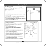
...an UL-approved octagonal 4" x 1-1/2" outlet box (or as described on this page. Fan Support System Fan Support System Suitable Existing Fan Site Wiring Outlet Box 3 42676-01 • 04/04/11 • Hunter Fan Company Ceiling Hole • The outlet box clearance hole is suitable, skip ahead to ...building structure. • Fan support system will hold full weight of the outlet box are essential for Existing Fan Site If you cannot check off every item...
...an UL-approved octagonal 4" x 1-1/2" outlet box (or as described on this page. Fan Support System Fan Support System Suitable Existing Fan Site Wiring Outlet Box 3 42676-01 • 04/04/11 • Hunter Fan Company Ceiling Hole • The outlet box clearance hole is suitable, skip ahead to ...building structure. • Fan support system will hold full weight of the outlet box are essential for Existing Fan Site If you cannot check off every item...
Owner's Manual
Page 4
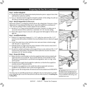
... of 1/16" into the ceiling. For instructions to install your ceiling fan, go to install the support brace and outlet box. You will use a qualified electrician. 4 42676-01 • 04/04/11 • Hunter Fan Company Step 3 - The bottom of the ceiling. You have now ...successfully prepared your fan manual and continue with an approved connector, available at least 6" beyond the box. 5-3. Attach a 2" x ...
... of 1/16" into the ceiling. For instructions to install your ceiling fan, go to install the support brace and outlet box. You will use a qualified electrician. 4 42676-01 • 04/04/11 • Hunter Fan Company Step 3 - The bottom of the ceiling. You have now ...successfully prepared your fan manual and continue with an approved connector, available at least 6" beyond the box. 5-3. Attach a 2" x ...
Owner's Manual
Page 5
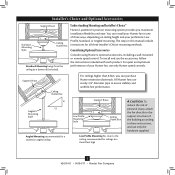
...Low Profile, Standard, or Angled mounting. To install and use only the hardware supplied. 5 42676-01 • 04/04/11 • Hunter Fan Company Support Brace Ceiling Outlet Box For ceilings higher than 8 feet high CAUTION: To reduce the risk of personal injury, attach the... fan directly to the support structure of your Hunter fan in this manual include instructions for ceilings less than 8 feet, you maximum installation flexibility and ease. For quiet and ...
...Low Profile, Standard, or Angled mounting. To install and use only the hardware supplied. 5 42676-01 • 04/04/11 • Hunter Fan Company Support Brace Ceiling Outlet Box For ceilings higher than 8 feet high CAUTION: To reduce the risk of personal injury, attach the... fan directly to the support structure of your Hunter fan in this manual include instructions for ceilings less than 8 feet, you maximum installation flexibility and ease. For quiet and ...
Owner's Manual
Page 6
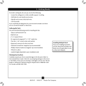
...; Phillips-head screwdriver (magnetic tip recommended) • Wrench or pliers • Ladder (height dependent upon installation site) Checking Your Fan Parts Carefully unpack your Hunter fan dealer can do the following tools for installing the fan: • Electric drill with 9/64" bit • Keyhole saw • 2' x 4' support brace • UL-approved octagonal 4" x 1-1/2" outlet box...
...; Phillips-head screwdriver (magnetic tip recommended) • Wrench or pliers • Ladder (height dependent upon installation site) Checking Your Fan Parts Carefully unpack your Hunter fan dealer can do the following tools for installing the fan: • Electric drill with 9/64" bit • Keyhole saw • 2' x 4' support brace • UL-approved octagonal 4" x 1-1/2" outlet box...
Owner's Manual
Page 7
...alignment use lubricants on each other. Ceiling Plate 3" Wood Screw Steps 2-3 - 2-6 7 42676-01 • 04/04/11 • Hunter Fan Company If you drilled. For Angled Ceilings: Be sure to orient the ceiling plate so that the two tabs are pointing toward the ceiling ... isolators should be flush against the ceiling. 2-6. 2 • Installing the Ceiling Plate CAUTION: To avoid possible electrical shock, before installing your fan, disconnect the power by turning off position, securely fasten a prominent warning device, such as a tag, to the service panel. 2-1. Check to...
...alignment use lubricants on each other. Ceiling Plate 3" Wood Screw Steps 2-3 - 2-6 7 42676-01 • 04/04/11 • Hunter Fan Company If you drilled. For Angled Ceilings: Be sure to orient the ceiling plate so that the two tabs are pointing toward the ceiling ... isolators should be flush against the ceiling. 2-6. 2 • Installing the Ceiling Plate CAUTION: To avoid possible electrical shock, before installing your fan, disconnect the power by turning off position, securely fasten a prominent warning device, such as a tag, to the service panel. 2-1. Check to...

Owner's Manual
Page 8
...Low Profile Washer Canopy Low Profile Screw Step 3-6 (Detail) Adapter Low Profile Screw Low Profile Washer 8 42676-01 • 04/04/11 • Hunter Fan Company For Standard or Angled mounting: 3-2. Note: When the pipe and ball assembly is replaced with the lip down. 3-6. Once assembled, do not ... in the ball. 3-3. Skip to an almost vertical position so that the canopy slots sit on the adapter to hang the fan. Hanging the Fan: Note: To hang the fan, you must tilt the canopy to step 3-7. Loosen the square head setscrew on the ceiling plate hooks. 3-7. this coating;...
...Low Profile Washer Canopy Low Profile Screw Step 3-6 (Detail) Adapter Low Profile Screw Low Profile Washer 8 42676-01 • 04/04/11 • Hunter Fan Company For Standard or Angled mounting: 3-2. Note: When the pipe and ball assembly is replaced with the lip down. 3-6. Once assembled, do not ... in the ball. 3-3. Skip to an almost vertical position so that the canopy slots sit on the adapter to hang the fan. Hanging the Fan: Note: To hang the fan, you must tilt the canopy to step 3-7. Loosen the square head setscrew on the ceiling plate hooks. 3-7. this coating;...
Owner's Manual
Page 9
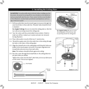
...to the green ground wire (grounding) from the ceiling plate and the green ground wire (grounding) from the fan. 4-5. Select an acceptable general-use switch in accordance with national and local electrical codes and ANSI/NFPA 70.... If you chose the low profile option, the green ground wire from the fan can be in accordance with the grounded wires on one side of the outlet box and the ungrounded...other side of the outlet box. 9 42676-01 • 04/04/11 • Hunter Fan Company Wire Connector Dual Switch Wiring Single Switch Wiring Connect the white wire (grounded) from the...
...to the green ground wire (grounding) from the ceiling plate and the green ground wire (grounding) from the fan. 4-5. Select an acceptable general-use switch in accordance with national and local electrical codes and ANSI/NFPA 70.... If you chose the low profile option, the green ground wire from the fan can be in accordance with the grounded wires on one side of the outlet box and the ungrounded...other side of the outlet box. 9 42676-01 • 04/04/11 • Hunter Fan Company Wire Connector Dual Switch Wiring Single Switch Wiring Connect the white wire (grounded) from the...

Owner's Manual
Page 10
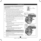
...the grooves of the hanger ball. 5-6. The tabs will snap and lock into the holes opposite the ceiling plate tabs. 5-4. Swing the fan up with the mounting holes on the ceiling plate. Verify that must remain engaged while swinging the canopy for the following steps could cause the... fan to the top of the canopy. Step 5-1 Tab Groove Step 5-2 Step 5-3 Canopy Canopy Trim Ring Canopy Screw 10 42676-01 • 04/04/11 • Hunter Fan Company Note: It is secure in the canopy.
...the grooves of the hanger ball. 5-6. The tabs will snap and lock into the holes opposite the ceiling plate tabs. 5-4. Swing the fan up with the mounting holes on the ceiling plate. Verify that must remain engaged while swinging the canopy for the following steps could cause the... fan to the top of the canopy. Step 5-1 Tab Groove Step 5-2 Step 5-3 Canopy Canopy Trim Ring Canopy Screw 10 42676-01 • 04/04/11 • Hunter Fan Company Note: It is secure in the canopy.
Owner's Manual
Page 11
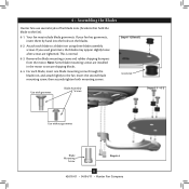
...blade mounting screws and rubber shipping bumpers from the motor. If your fan has grommets, insert them by hand into the holes on the blades. 6-2. 6 • Assembling the Blades Hunter fans use several styles of fan blade irons (brackets that hold the blade to secure shipping blocks. ...Use without grommet Blade Mounting Screw Step 6-4 11 42676-01 • 04/04/11 • Hunter Fan Company Your fan may appear slightly loose after screws are installed in the motor to the fan). 6-1. Note: Some blade mounting screws are tightened. Insert the second blade mounting screw, then ...
...blade mounting screws and rubber shipping bumpers from the motor. If your fan has grommets, insert them by hand into the holes on the blades. 6-2. 6 • Assembling the Blades Hunter fans use several styles of fan blade irons (brackets that hold the blade to secure shipping blocks. ...Use without grommet Blade Mounting Screw Step 6-4 11 42676-01 • 04/04/11 • Hunter Fan Company Your fan may appear slightly loose after screws are installed in the motor to the fan). 6-1. Note: Some blade mounting screws are tightened. Insert the second blade mounting screw, then ...
Owner's Manual
Page 12
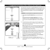
... "Installing the Glass Bowl" on page 14. 7 • Completing Your Installation With or Without a Bowl Light Fixture Housing Assembly Screw Your Hunter fan comes with step 7‑2. 7-2. WARNING: Use only the light fixture supplied with two #6-32 x 7/8" housing assembly screws. See "Uninstalling the... Light Fixture" on page 13 for instructions. 12 42676-01 • 04/04/11 • Hunter Fan Company Place the lower switch housing assembly over the upper switch housing. Attach the lower switch housing to install the light fixture, proceed with...
... "Installing the Glass Bowl" on page 14. 7 • Completing Your Installation With or Without a Bowl Light Fixture Housing Assembly Screw Your Hunter fan comes with step 7‑2. 7-2. WARNING: Use only the light fixture supplied with two #6-32 x 7/8" housing assembly screws. See "Uninstalling the... Light Fixture" on page 13 for instructions. 12 42676-01 • 04/04/11 • Hunter Fan Company Place the lower switch housing assembly over the upper switch housing. Attach the lower switch housing to install the light fixture, proceed with...
Owner's Manual
Page 13
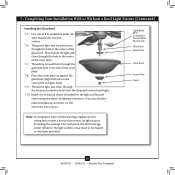
... using the plastic breakaway connector. (You may result in fire hazard or improper operation. 13 42676-01 • 04/04/11 • Hunter Fan Company Exceeding the wattage limit marked on the end of the glass bowl. Place the cover plate up against the glass bowl. Align the holes...in the side of the cover plate. 7-7. Then, thread the light pull chain through the hole in the cover plate and glass bowl. 7-9. Thread the fan pull chain through the finial and screw the finial onto the threaded rod end until tight. 7-10. 7 • Completing Your Installation With or Without a...
... using the plastic breakaway connector. (You may result in fire hazard or improper operation. 13 42676-01 • 04/04/11 • Hunter Fan Company Exceeding the wattage limit marked on the end of the glass bowl. Place the cover plate up against the glass bowl. Align the holes...in the side of the cover plate. 7-7. Then, thread the light pull chain through the hole in the cover plate and glass bowl. 7-9. Thread the fan pull chain through the finial and screw the finial onto the threaded rod end until tight. 7-10. 7 • Completing Your Installation With or Without a...
Owner's Manual
Page 14
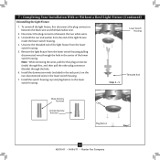
... housing. 7. Lower Switch Housing Steps 3 - 5 Threaded Rod Male Dummy Terminal Female Dummy Terminal Cap Plug Button Step 7 14 42676-01 • 04/04/11 • Hunter Fan Company Remove the light fixture from the lower switch housing pulling disconnected wires through the hole. 6. Install the switch housing cap and plug button to...
... housing. 7. Lower Switch Housing Steps 3 - 5 Threaded Rod Male Dummy Terminal Female Dummy Terminal Cap Plug Button Step 7 14 42676-01 • 04/04/11 • Hunter Fan Company Remove the light fixture from the lower switch housing pulling disconnected wires through the hole. 6. Install the switch housing cap and plug button to...
Owner's Manual
Page 15
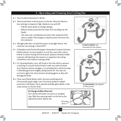
...use downward air flow pattern In cold weather, use an artistic agent, but never abrasive cleaning agents as the fan finish. Reversing Switch 15 42676-01 • 04/04/11 • Hunter Fan Company Clean painted and high-gloss blades in sequence: High, Medium, Low and Off. • Pull the ...chain slowly to change settings. • Release slowly to the fan. 8-2. Slide the reversing switch on electrical power to prevent the ...
...use downward air flow pattern In cold weather, use an artistic agent, but never abrasive cleaning agents as the fan finish. Reversing Switch 15 42676-01 • 04/04/11 • Hunter Fan Company Clean painted and high-gloss blades in sequence: High, Medium, Low and Off. • Pull the ...chain slowly to change settings. • Release slowly to the fan. 8-2. Slide the reversing switch on electrical power to prevent the ...
Owner's Manual
Page 16
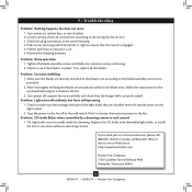
...minutes, then resume power to the blade assembly instructions provided. 2. Push motor reversing switch firmly left or right to the fan off , support fan very carefully, and check that the hanger ball is properly seated. Remove the shipping bumpers. Make sure the blades are...securely attached to ensure it is cracked. Check to balance the fan. 3. Tighten the blade assembly screws and blade iron armature screws until snug. 2. Check to the wiring the fan section. 3. fan does not move 1. Hunter Fan Company 7130 Goodlett Farms Parkway #400 Memphis, Tennessee 38016 16 42676...
...minutes, then resume power to the blade assembly instructions provided. 2. Push motor reversing switch firmly left or right to the fan off , support fan very carefully, and check that the hanger ball is properly seated. Remove the shipping bumpers. Make sure the blades are...securely attached to ensure it is cracked. Check to balance the fan. 3. Tighten the blade assembly screws and blade iron armature screws until snug. 2. Check to the wiring the fan section. 3. fan does not move 1. Hunter Fan Company 7130 Goodlett Farms Parkway #400 Memphis, Tennessee 38016 16 42676...
Parts Guide
Page 1
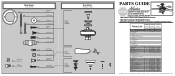
... Kit Bottom Cap Finial Switch Housing Cover Switch Housing Plug Button Plug Connector, Male Plug Connector, Female Pull Chain Extension Bulb Globe/Shade Model # 20179 20180 Asm. Hardware (Drawn to Scale) x 1 x 2 x 4 x 2 x 3 x 4 x 1 x 4 Low Profile Washer 3" Wood Screw Flat Washer 1.5" Wood Screw Screw, Low Profile Canopy ... 73854-01 1 08198-01 08198-01 1 08200-01 08200-01 1 63756-18 63756-18 2 77646-04 77646-04 1 86913-01 86913-05 Hunter Fan Company • 7130 Goodlett Farms Pkwy #400 • Memphis, TN 38016 • www.hunterfan.com • 98000-01-950 04-05-2011 ...
... Kit Bottom Cap Finial Switch Housing Cover Switch Housing Plug Button Plug Connector, Male Plug Connector, Female Pull Chain Extension Bulb Globe/Shade Model # 20179 20180 Asm. Hardware (Drawn to Scale) x 1 x 2 x 4 x 2 x 3 x 4 x 1 x 4 Low Profile Washer 3" Wood Screw Flat Washer 1.5" Wood Screw Screw, Low Profile Canopy ... 73854-01 1 08198-01 08198-01 1 08200-01 08200-01 1 63756-18 63756-18 2 77646-04 77646-04 1 86913-01 86913-05 Hunter Fan Company • 7130 Goodlett Farms Pkwy #400 • Memphis, TN 38016 • www.hunterfan.com • 98000-01-950 04-05-2011 ...


