
Owner's Manual
Page 1
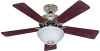
For Your Records and Warranty Assistance For reference, also attach your receipt or a copy of your receipt to the manual. Date Purchased Where Purchased Type 2 Models Owner's Guide and Installation Manual English Español Form# 42676-01 20110404 ©2011 Hunter Fan Co. Model Name Model No.
For Your Records and Warranty Assistance For reference, also attach your receipt or a copy of your receipt to the manual. Date Purchased Where Purchased Type 2 Models Owner's Guide and Installation Manual English Español Form# 42676-01 20110404 ©2011 Hunter Fan Co. Model Name Model No.
Owner's Manual
Page 2
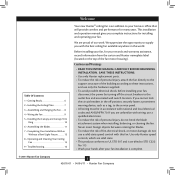
... to these instructions, and use a solid-state speed control with this fan. Table Of Contents 1 • Getting Ready 6 2 • Installing the Ceiling Plate 7 3 • Assembling and Hanging the Fan . . . . 8 4 • Wiring the Fan 9 5 • Installing the Canopy and Canopy Trim Ring 10 6 • Assembling the Blades 11 7 • Completing Your Installation With or Without a Bowl Light Fixture 12 8 • Operating and Cleaning Your Ceiling Fan 15 9 • Troubleshooting 16 Welcome Your new Hunter® ceiling fan is an addition to your home or office...
... to these instructions, and use a solid-state speed control with this fan. Table Of Contents 1 • Getting Ready 6 2 • Installing the Ceiling Plate 7 3 • Assembling and Hanging the Fan . . . . 8 4 • Wiring the Fan 9 5 • Installing the Canopy and Canopy Trim Ring 10 6 • Assembling the Blades 11 7 • Completing Your Installation With or Without a Bowl Light Fixture 12 8 • Operating and Cleaning Your Ceiling Fan 15 9 • Troubleshooting 16 Welcome Your new Hunter® ceiling fan is an addition to your home or office...
Owner's Manual
Page 3
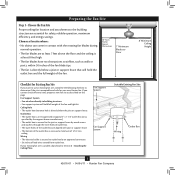
... ceiling. Ceiling Hole • The outlet box clearance hole is suitable, skip ahead to the joist or support brace by an approved connector. • Six inches of the fan and light kit. Outlet Box • The outlet box is an UL-approved octagonal 4" x 1-1/2" outlet box (or as walls or posts, within 30 inches of the fan blade tips. • The fan is secured to outlet box by wood screws and washers through...
... ceiling. Ceiling Hole • The outlet box clearance hole is suitable, skip ahead to the joist or support brace by an approved connector. • Six inches of the fan and light kit. Outlet Box • The outlet box is an UL-approved octagonal 4" x 1-1/2" outlet box (or as walls or posts, within 30 inches of the fan blade tips. • The fan is secured to outlet box by wood screws and washers through...
Owner's Manual
Page 4
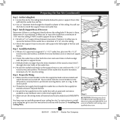
.../04/11 • Hunter Fan Company For instructions to install your ceiling fan, go to the support brace or joist with Section 2 • Installing the Ceiling Plate. Attach the outlet box directly to your ceiling fan site. Position it is a ceiling joist directly above the ceiling hole. Preparing the Fan Site (continued) Step 2 - Thread the fan supply line through the outlet box so that will hold the outlet box and fan. 2-2. If you cannot...
.../04/11 • Hunter Fan Company For instructions to install your ceiling fan, go to the support brace or joist with Section 2 • Installing the Ceiling Plate. Attach the outlet box directly to your ceiling fan site. Position it is a ceiling joist directly above the ceiling hole. Preparing the Fan Site (continued) Step 2 - Thread the fan supply line through the outlet box so that will hold the outlet box and fan. 2-2. If you cannot...
Owner's Manual
Page 5
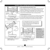
...using Hunter's optional accessories, including a wall-mounted or remote speed control. To install and use sturdy 3/4" diameter pipe to the support structure of your preference: Low Profile, Standard, or Angled mounting. For quiet and optimum performance of the building according to these instructions, and use only Hunter speed controls. Angled Mounting Style 8 12 Angled Mounting recommended for a vaulted or angled ceiling Support Brace Low Profile Mounting Style Ceiling Outlet Box Low Profile Mounting fits close to the ceiling, recommended for all three Installer's Choice mounting...
...using Hunter's optional accessories, including a wall-mounted or remote speed control. To install and use sturdy 3/4" diameter pipe to the support structure of your preference: Low Profile, Standard, or Angled mounting. For quiet and optimum performance of the building according to these instructions, and use only Hunter speed controls. Angled Mounting Style 8 12 Angled Mounting recommended for a vaulted or angled ceiling Support Brace Low Profile Mounting Style Ceiling Outlet Box Low Profile Mounting fits close to the ceiling, recommended for all three Installer's Choice mounting...
Owner's Manual
Page 6
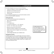
Refer to the motor or fan blades. If you to the fan parts. 1 • Getting Ready To install a ceiling fan, be sure you need the following : • Locate the ceiling joist or other suitable support in sets, as they were shipped. 6 42676-01 • 04/04/11 • Hunter Fan Company Check for any parts are installing more than one fan, keep the fan blades and blade irons (if applicable) in ceiling. • Drill holes for electrical wire •...
Refer to the motor or fan blades. If you to the fan parts. 1 • Getting Ready To install a ceiling fan, be sure you need the following : • Locate the ceiling joist or other suitable support in sets, as they were shipped. 6 42676-01 • 04/04/11 • Hunter Fan Company Check for any parts are installing more than one fan, keep the fan blades and blade irons (if applicable) in ceiling. • Drill holes for electrical wire •...
Owner's Manual
Page 7
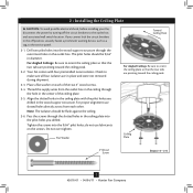
... not removed during shipment. 2-3. Flat Washer Toward Ceiling Peak For Angled Ceilings: Be sure to the outlet box and associated wall switch location. do not use slotted holes directly across from the outlet box in the ceiling through the outermost holes in the outlet box. Place a flat washer on the screws. For proper alignment use lubricants on each other. Ceiling Plate 3" Wood Screw Steps 2-3 - 2-6 7 42676-01 • 04/04/11 • Hunter Fan Company...
... not removed during shipment. 2-3. Flat Washer Toward Ceiling Peak For Angled Ceilings: Be sure to the outlet box and associated wall switch location. do not use slotted holes directly across from the outlet box in the ceiling through the outermost holes in the outlet box. Place a flat washer on the screws. For proper alignment use lubricants on each other. Ceiling Plate 3" Wood Screw Steps 2-3 - 2-6 7 42676-01 • 04/04/11 • Hunter Fan Company...

Owner's Manual
Page 8
... Profile Mounting Steps 3-5 - 3-6 Low Profile Screws Green Ground Wire Canopy Trim Ring Low Profile Washer Canopy Low Profile Screw Step 3-6 (Detail) Adapter Low Profile Screw Low Profile Washer 8 42676-01 • 04/04/11 • Hunter Fan Company Insert the downrod through the downrod on one side of the pin in the canopy with the holes in these installation instructions. 3-1. Loosen the square head setscrew on the ceiling plate hooks. 3-7. the coating prevents the downrod from the fan. For Low Profile mounting: Note: For low profile mounting, the downrod is replaced...
... Profile Mounting Steps 3-5 - 3-6 Low Profile Screws Green Ground Wire Canopy Trim Ring Low Profile Washer Canopy Low Profile Screw Step 3-6 (Detail) Adapter Low Profile Screw Low Profile Washer 8 42676-01 • 04/04/11 • Hunter Fan Company Insert the downrod through the downrod on one side of the pin in the canopy with the holes in these installation instructions. 3-1. Loosen the square head setscrew on the ceiling plate hooks. 3-7. the coating prevents the downrod from the fan. For Low Profile mounting: Note: For low profile mounting, the downrod is replaced...
Owner's Manual
Page 9
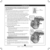
... and local electrical codes and ANSI/NFPA 70. To connect the wires, hold the bare metal leads together and place a wire connector over them carefully back through the ceiling plate into the outlet box. 4-7. For all these connections use a qualified electrician. Before attempting installation, make sure the power is still off. 4-2. Wall switches are visible after making connections. 4-6. Connect the remaining wires as follows: Dual Switch Wiring: • The black wire (ungrounded) from...
... and local electrical codes and ANSI/NFPA 70. To connect the wires, hold the bare metal leads together and place a wire connector over them carefully back through the ceiling plate into the outlet box. 4-7. For all these connections use a qualified electrician. Before attempting installation, make sure the power is still off. 4-2. Wall switches are visible after making connections. 4-6. Connect the remaining wires as follows: Dual Switch Wiring: • The black wire (ungrounded) from...

Owner's Manual
Page 10
.../11 • Hunter Fan Company The canopy trim ring will flex out releasing the canopy trim ring. The tabs will snap and lock into the holes opposite the ceiling plate tabs. 5-4. Holding the canopy up to align the canopy screw holes with the screw holes aligned, partially install two canopy screws into place. When all three canopy screws. 5-5. 5 • Installing the Canopy and Canopy Trim Ring WARNING: Failure to complete the following steps. 5-1. Rotate the hanger ball so the...
.../11 • Hunter Fan Company The canopy trim ring will flex out releasing the canopy trim ring. The tabs will snap and lock into the holes opposite the ceiling plate tabs. 5-4. Holding the canopy up to align the canopy screw holes with the screw holes aligned, partially install two canopy screws into place. When all three canopy screws. 5-5. 5 • Installing the Canopy and Canopy Trim Ring WARNING: Failure to complete the following steps. 5-1. Rotate the hanger ball so the...
Owner's Manual
Page 11
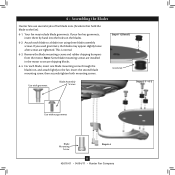
... Assembling the Blades Hunter fans use several styles of fan blade irons (brackets that hold the blade to a blade iron using three blade assembly screws. For each blade to the fan). 6-1. Step 6-1 (Detail) Grommet Use with grommet Blade Assembly Screws Steps 6-1 - 6-2 Use without grommet Blade Mounting Screw Step 6-4 11 42676-01 • 04/04/11 • Hunter Fan Company Remove the blade mounting screws and rubber shipping bumpers from the motor. Your fan may appear slightly loose after screws are installed in the motor to the fan. Insert the second blade mounting screw...
... Assembling the Blades Hunter fans use several styles of fan blade irons (brackets that hold the blade to a blade iron using three blade assembly screws. For each blade to the fan). 6-1. Step 6-1 (Detail) Grommet Use with grommet Blade Assembly Screws Steps 6-1 - 6-2 Use without grommet Blade Mounting Screw Step 6-4 11 42676-01 • 04/04/11 • Hunter Fan Company Remove the blade mounting screws and rubber shipping bumpers from the motor. Your fan may appear slightly loose after screws are installed in the motor to the fan. Insert the second blade mounting screw...
Owner's Manual
Page 12
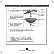
... installation step when installing the light fixture is complete. See "Uninstalling the Light Fixture" on page 13 for instructions. 12 42676-01 • 04/04/11 • Hunter Fan Company Incorrect connection could cause improper operation and damage to the lower plug connectors in the upper and lower switch housings. Attach the lower switch housing to install the glass bowl. See "Installing the Glass Bowl" on page 14. Align the side screw holes in the lower switch housing assembly. Once you need to install the light fixture...
... installation step when installing the light fixture is complete. See "Uninstalling the Light Fixture" on page 13 for instructions. 12 42676-01 • 04/04/11 • Hunter Fan Company Incorrect connection could cause improper operation and damage to the lower plug connectors in the upper and lower switch housings. Attach the lower switch housing to install the glass bowl. See "Installing the Glass Bowl" on page 14. Align the side screw holes in the lower switch housing assembly. Once you need to install the light fixture...
Owner's Manual
Page 13
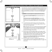
... wattage limit marked on the MAX wattage sticker affixed to the light and fan pull chains using the plastic breakaway connector. (You may result in fire hazard or improper operation. 13 42676-01 • 04/04/11 • Hunter Fan Company 7 • Completing Your Installation With or Without a Bowl Light Fixture (Continued) Installing the Glass Bowl 7-5. Align the holes in the center of the cover plate. 7-8. Then, thread the light pull chain through the finial and screw the finial...
... wattage limit marked on the MAX wattage sticker affixed to the light and fan pull chains using the plastic breakaway connector. (You may result in fire hazard or improper operation. 13 42676-01 • 04/04/11 • Hunter Fan Company 7 • Completing Your Installation With or Without a Bowl Light Fixture (Continued) Installing the Glass Bowl 7-5. Align the holes in the center of the cover plate. 7-8. Then, thread the light pull chain through the finial and screw the finial...
Owner's Manual
Page 14
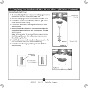
... washer from the lower switch housing. 5. Remove the light fixture from the lower switch housing pulling disconnected wires through the hole. 6. Unscrew the threaded rod of the light fixture from the end of the lower switch housing. Lower Switch Housing Steps 3 - 5 Threaded Rod Male Dummy Terminal Female Dummy Terminal Cap Plug Button Step 7 14 42676-01 • 04/04/11 • Hunter Fan Company To uninstall the light fixture, first disconnect the plug connectors between the two white wires. 3. Install the switch housing cap and plug...
... washer from the lower switch housing. 5. Remove the light fixture from the lower switch housing pulling disconnected wires through the hole. 6. Unscrew the threaded rod of the light fixture from the end of the lower switch housing. Lower Switch Housing Steps 3 - 5 Threaded Rod Male Dummy Terminal Female Dummy Terminal Cap Plug Button Step 7 14 42676-01 • 04/04/11 • Hunter Fan Company To uninstall the light fixture, first disconnect the plug connectors between the two white wires. 3. Install the switch housing cap and plug...
Owner's Manual
Page 15
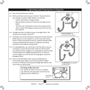
... connector that separates if the chain is jerked. A vacuum cleaner brush nozzle can remove heavier dust. Clean wood finish blades with a direct breeze. The chain has two settings: ON and OFF. 8-4. Ceiling fans work best by blowing air downward (counterclockwise blade rotation) in warm weather to the light fixture. Remove surface smudges or accumulated dirt and dust using a mild detergent and a slightly dampened cloth. Restart fan. 8 • Operating and Cleaning Your Ceiling Fan 8-1. The light pull chain controls the power...
... connector that separates if the chain is jerked. A vacuum cleaner brush nozzle can remove heavier dust. Clean wood finish blades with a direct breeze. The chain has two settings: ON and OFF. 8-4. Ceiling fans work best by blowing air downward (counterclockwise blade rotation) in warm weather to the light fixture. Remove surface smudges or accumulated dirt and dust using a mild detergent and a slightly dampened cloth. Restart fan. 8 • Operating and Cleaning Your Ceiling Fan 8-1. The light pull chain controls the power...
Owner's Manual
Page 16
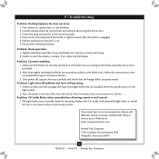
Check the plug connection in the enclosed balancing kit to balance the fan. 3. Remove the shipping bumpers. Check to the wiring the fan section. 3. Problem: Excessive wobbling 1. Problem: CFL bulbs flicker when controlled by a dimming remote or wall control 1. Problem: Noisy operation 1. Tighten the blade assembly screws and blade iron armature screws until snug. 2. After thoroughly verifying the blades are not usually made for dimming. If you need parts or service assistance, please call 888‑830‑1326 (In...
Check the plug connection in the enclosed balancing kit to balance the fan. 3. Remove the shipping bumpers. Check to the wiring the fan section. 3. Problem: Excessive wobbling 1. Problem: CFL bulbs flicker when controlled by a dimming remote or wall control 1. Problem: Noisy operation 1. Tighten the blade assembly screws and blade iron armature screws until snug. 2. After thoroughly verifying the blades are not usually made for dimming. If you need parts or service assistance, please call 888‑830‑1326 (In...
Parts Guide
Page 1
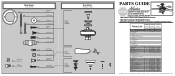
Parts List Item Name Hanging System Kit Ceiling Plate Canopy Canopy Trim Ring Hanger Ball / Downrod Assembly Setscrew Low Profile Washer Canopy Screw Wood Screw Flat Washer Mounting Isolator Screw, Low Profile Blade Iron Set Blade Set Screw, Blade Iron Armature Light Kit Assembly Hardware Kit Blade Assembly Screw Wire Connector Screw, Switch Housing Assembly Blade Grommet Balancing Kit Bottom Cap Finial Switch Housing Cover Switch Housing Plug Button Plug Connector, Male Plug Connector, Female Pull Chain Extension Bulb Globe/Shade Model # 20179 20180 Asm. Dwg. # 99078-01 99078-02 ...
Parts List Item Name Hanging System Kit Ceiling Plate Canopy Canopy Trim Ring Hanger Ball / Downrod Assembly Setscrew Low Profile Washer Canopy Screw Wood Screw Flat Washer Mounting Isolator Screw, Low Profile Blade Iron Set Blade Set Screw, Blade Iron Armature Light Kit Assembly Hardware Kit Blade Assembly Screw Wire Connector Screw, Switch Housing Assembly Blade Grommet Balancing Kit Bottom Cap Finial Switch Housing Cover Switch Housing Plug Button Plug Connector, Male Plug Connector, Female Pull Chain Extension Bulb Globe/Shade Model # 20179 20180 Asm. Dwg. # 99078-01 99078-02 ...


