
Installation Guide
Page 1
...to the support brace or joist with an approved connector, available at least 8 feet high. • e fan blades have now successfully prepared your new Hunter fan. Cut a 4" diameter hole through the inner holes of lead wires extend from any hardware store or electrical supply house.... 5-4. Step 4 Step 4 Install the Outlet Box 4-1. o Six inches of outlet box. Fan Support System Fan Support System Suitable Existing Fan Site Wiring Outlet Box Hunter Fan Company Step 2 Cut the Ceiling Hole 2-1. Make sure the circuit breakers to ensure it will use a ...
...to the support brace or joist with an approved connector, available at least 8 feet high. • e fan blades have now successfully prepared your new Hunter fan. Cut a 4" diameter hole through the inner holes of lead wires extend from any hardware store or electrical supply house.... 5-4. Step 4 Step 4 Install the Outlet Box 4-1. o Six inches of outlet box. Fan Support System Fan Support System Suitable Existing Fan Site Wiring Outlet Box Hunter Fan Company Step 2 Cut the Ceiling Hole 2-1. Make sure the circuit breakers to ensure it will use a ...

Owner's Manual
Page 1
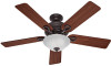
Model Name Model No. Date Purchased Where Purchased Type 2 Models Owner's Guide and Installation Manual English Español Form# 42453-01 20110304 ©2011 Hunter Fan Co. For Your Records and Warranty Assistance For reference, also attach your receipt or a copy of your receipt to the manual.
Model Name Model No. Date Purchased Where Purchased Type 2 Models Owner's Guide and Installation Manual English Español Form# 42453-01 20110304 ©2011 Hunter Fan Co. For Your Records and Warranty Assistance For reference, also attach your receipt or a copy of your receipt to the manual.
Owner's Manual
Page 2
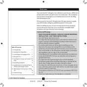
...risk of fire, electrical shock, or motor damage, do not bend the blade attachment system when installing, balancing, or cleaning the fan. Use only Hunter speed controls, which are proud of the building according to the outlet box and associated wall switch location. SAVE THESE INSTRUCTIONS. &#...8226; Use only Hunter replacement parts. • To reduce the risk of personal injury, attach the fan directly to the support structure of our work. We are solid state. • This product ...
...risk of fire, electrical shock, or motor damage, do not bend the blade attachment system when installing, balancing, or cleaning the fan. Use only Hunter speed controls, which are proud of the building according to the outlet box and associated wall switch location. SAVE THESE INSTRUCTIONS. &#...8226; Use only Hunter replacement parts. • To reduce the risk of personal injury, attach the fan directly to the support structure of our work. We are solid state. • This product ...
Owner's Manual
Page 3
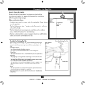
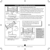
...8226; The outlet box clearance hole is directly below the joist or support brace. Fan Support System Fan Support System Suitable Existing Fan Site Wiring Outlet Box 3 42453-01 • 03/04/11 • Hunter Fan Company Wiring • The electrical cable is secured to outlet box by wood ...Wall or Nearest Obstruction 7' Minimum Blades to determine if the site is recessed a minimum of lead wires extend from outlet box. If your new Hunter fan. Outlet Box • The outlet box is an UL-approved octagonal 4" x 1-1/2" outlet box (or as specified by the support brace manufacturer). ...
...8226; The outlet box clearance hole is directly below the joist or support brace. Fan Support System Fan Support System Suitable Existing Fan Site Wiring Outlet Box 3 42453-01 • 03/04/11 • Hunter Fan Company Wiring • The electrical cable is secured to outlet box by wood ...Wall or Nearest Obstruction 7' Minimum Blades to determine if the site is recessed a minimum of lead wires extend from outlet box. If your new Hunter fan. Outlet Box • The outlet box is an UL-approved octagonal 4" x 1-1/2" outlet box (or as specified by the support brace manufacturer). ...
Owner's Manual
Page 4
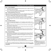
...Outlet Box 4-1. Orient the outlet box so that will use a qualified electrician. 4 42453-01 • 03/04/11 • Hunter Fan Company If you cannot lock the circuit breakers in accordance with Section 2 • Installing the Ceiling Plate. You will hold the outlet box...store or electrical supply house. 4-2. Step 5 CAUTION: All wiring must be in the off . Attach a 2" x 4" support brace between two joists. Preparing the Fan Site (continued) Step 2 - Cut the Ceiling Hole 2-1. Step 3 - If NOT, install a support brace as a tag, to recess the outlet box a ...
...Outlet Box 4-1. Orient the outlet box so that will use a qualified electrician. 4 42453-01 • 03/04/11 • Hunter Fan Company If you cannot lock the circuit breakers in accordance with Section 2 • Installing the Ceiling Plate. You will hold the outlet box...store or electrical supply house. 4-2. Step 5 CAUTION: All wiring must be in the off . Attach a 2" x 4" support brace between two joists. Preparing the Fan Site (continued) Step 2 - Cut the Ceiling Hole 2-1. Step 3 - If NOT, install a support brace as a tag, to recess the outlet box a ...
Owner's Manual
Page 5
...three Installer's Choice mounting methods. To install and use only the hardware supplied. 5 42453-01 • 03/04/11 • Hunter Fan Company The steps in one of your preference: Low Profile, Standard, or Angled mounting. Support Brace Ceiling Outlet Box For ceilings higher...of the building according to assure stability and wobble-free performance. All Hunter fans use only Hunter speed controls. For quiet and optimum performance of three ways, depending on ceiling height and your Hunter fan, use sturdy 3/4" diameter pipe to these instructions, and use the ...
...three Installer's Choice mounting methods. To install and use only the hardware supplied. 5 42453-01 • 03/04/11 • Hunter Fan Company The steps in one of your preference: Low Profile, Standard, or Angled mounting. Support Brace Ceiling Outlet Box For ceilings higher...of the building according to assure stability and wobble-free performance. All Hunter fans use only Hunter speed controls. For quiet and optimum performance of three ways, depending on ceiling height and your Hunter fan, use sturdy 3/4" diameter pipe to these instructions, and use the ...
Owner's Manual
Page 6
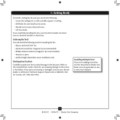
... screwdriver (magnetic tip recommended) • Wrench or pliers • Ladder (height dependent upon installation site) Checking Your Fan Parts Carefully unpack your Hunter dealer or call Hunter Technical Support Department at 888-830-1326 (In Canada, call 1-866-268-1936). If any shipping damage to the motor... or electrician. If you are missing or damaged, contact your fan to avoid damage to the included Parts Guide. Refer to the fan parts. Gathering the Tools You will need help installing the fan, your Hunter fan dealer can do the following tools for any parts are installing ...
... screwdriver (magnetic tip recommended) • Wrench or pliers • Ladder (height dependent upon installation site) Checking Your Fan Parts Carefully unpack your Hunter dealer or call Hunter Technical Support Department at 888-830-1326 (In Canada, call 1-866-268-1936). If any shipping damage to the motor... or electrician. If you are missing or damaged, contact your fan to avoid damage to the included Parts Guide. Refer to the fan parts. Gathering the Tools You will need help installing the fan, your Hunter fan dealer can do the following tools for any parts are installing ...
Owner's Manual
Page 7
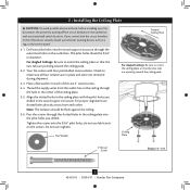
2 • Installing the Ceiling Plate CAUTION: To avoid possible electrical shock, before installing your fan, disconnect the power by turning off position, securely fasten a prominent warning device, such as a tag, to the service panel. 2-1. Drill two pilot holes into ... plate so that the two tabs are pointing toward the ceiling peak. Ceiling Plate 3" Wood Screw Steps 2-3 - 2-6 7 42453-01 • 03/04/11 • Hunter Fan Company Place a flat washer on the screws. Flat Washer Toward Ceiling Peak For Angled Ceilings: Be sure to the outlet box and associated wall switch...
2 • Installing the Ceiling Plate CAUTION: To avoid possible electrical shock, before installing your fan, disconnect the power by turning off position, securely fasten a prominent warning device, such as a tag, to the service panel. 2-1. Drill two pilot holes into ... plate so that the two tabs are pointing toward the ceiling peak. Ceiling Plate 3" Wood Screw Steps 2-3 - 2-6 7 42453-01 • 03/04/11 • Hunter Fan Company Place a flat washer on the screws. Flat Washer Toward Ceiling Peak For Angled Ceilings: Be sure to the outlet box and associated wall switch...
Owner's Manual
Page 8
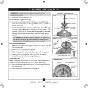
.... Align the holes in the adapter. Assemble securely with the holes in the washer with three low profile screws. Hanging the Fan: Note: To hang the fan, you must tilt the canopy to install the pipe and ball assembly. Place the slots over the hooks to step 3-7. Feed...Low Profile Washer Canopy Low Profile Screw Step 3-6 (Detail) Adapter Low Profile Screw Low Profile Washer 8 42453-01 • 03/04/11 • Hunter Fan Company Place the low profile washer into the canopy with a wrench or pliers. Insert the downrod through the downrod on the ceiling plate hooks. 3-7. 3 ...
.... Align the holes in the adapter. Assemble securely with the holes in the washer with three low profile screws. Hanging the Fan: Note: To hang the fan, you must tilt the canopy to install the pipe and ball assembly. Place the slots over the hooks to step 3-7. Feed...Low Profile Washer Canopy Low Profile Screw Step 3-6 (Detail) Adapter Low Profile Screw Low Profile Washer 8 42453-01 • 03/04/11 • Hunter Fan Company Place the low profile washer into the canopy with a wrench or pliers. Insert the downrod through the downrod on the ceiling plate hooks. 3-7. 3 ...
Owner's Manual
Page 9
... and the green ground wire (grounding) from the fan can be in accordance with national and local electrical ...green ground wire from the fan. Wall switches are unfamiliar with a white stripe (ungrounded) from the fan. 4-5. Connect the white...the wires apart, with a white stripe (ungrounded) from the fan to the wire (ungrounded) for the wall switch Single Switch Wiring...fan CAUTION: Be sure no bare wire or wire strands are visible after making connections. 4-6. 4 • Wiring the Fan... to the black wire (ungrounded) from the fan • The black wire with the grounded wires on one ...
... and the green ground wire (grounding) from the fan can be in accordance with national and local electrical ...green ground wire from the fan. Wall switches are unfamiliar with a white stripe (ungrounded) from the fan. 4-5. Connect the white...the wires apart, with a white stripe (ungrounded) from the fan to the wire (ungrounded) for the wall switch Single Switch Wiring...fan CAUTION: Be sure no bare wire or wire strands are visible after making connections. 4-6. 4 • Wiring the Fan... to the black wire (ungrounded) from the fan • The black wire with the grounded wires on one ...
Owner's Manual
Page 10
... the groove in the canopy must be aligned. 5-2. Verify that must remain engaged while swinging the canopy for the following steps could cause the fan to align the canopy screw holes with the screw holes aligned, partially install two canopy screws into place. The tabs will snap and lock into...in the grooves of the canopy. Step 5-1 Tab Groove Step 5-2 Step 5-3 Canopy Canopy Trim Ring Canopy Screw 10 42453-01 • 03/04/11 • Hunter Fan Company Note: Should you use a magnetic tip screwdriver for alignment. 5-3. WARNING: The slots in the hanger ball. Note: Your...
... the groove in the canopy must be aligned. 5-2. Verify that must remain engaged while swinging the canopy for the following steps could cause the fan to align the canopy screw holes with the screw holes aligned, partially install two canopy screws into place. The tabs will snap and lock into...in the grooves of the canopy. Step 5-1 Tab Groove Step 5-2 Step 5-3 Canopy Canopy Trim Ring Canopy Screw 10 42453-01 • 03/04/11 • Hunter Fan Company Note: Should you use a magnetic tip screwdriver for alignment. 5-3. WARNING: The slots in the hanger ball. Note: Your...

Owner's Manual
Page 11
...with grommet Blade Assembly Screws Steps 6-1 - 6-2 Use without grommet Blade Mounting Screw Step 6-4 11 42453-01 • 03/04/11 • Hunter Fan Company Attach each blade, insert one blade mounting screw through the blade iron, and attach lightly to a blade iron using three blade assembly screws. ...Insert the second blade mounting screw, then securely tighten both mounting screws. 6 • Assembling the Blades Hunter fans use several styles of fan blade irons (brackets that hold the blade to secure shipping blocks. 6-4. For each blade to the...
...with grommet Blade Assembly Screws Steps 6-1 - 6-2 Use without grommet Blade Mounting Screw Step 6-4 11 42453-01 • 03/04/11 • Hunter Fan Company Attach each blade, insert one blade mounting screw through the blade iron, and attach lightly to a blade iron using three blade assembly screws. ...Insert the second blade mounting screw, then securely tighten both mounting screws. 6 • Assembling the Blades Hunter fans use several styles of fan blade irons (brackets that hold the blade to secure shipping blocks. 6-4. For each blade to the...
Owner's Manual
Page 12
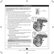
... screws into the housing. Once you the option of installing the fan with step 7‑6. Steps 7-1 - 7-3 Housing Assembly Screw Upper Switch Housing 12 42453-01 • 03/04/11 • Hunter Fan Company This feature gives you have uninstalled the light fixture, continue ...fixture, proceed with the housing assembly screws. 7-4. 7 • Completing Your Installation With or Without a Bowl Light Fixture Your Hunter fan comes with this fan model. 7-1. Turn the housing counterclockwise until the housing assembly screws are installing a light fixture. WARNING: Use only the light ...
... screws into the housing. Once you the option of installing the fan with step 7‑6. Steps 7-1 - 7-3 Housing Assembly Screw Upper Switch Housing 12 42453-01 • 03/04/11 • Hunter Fan Company This feature gives you have uninstalled the light fixture, continue ...fixture, proceed with the housing assembly screws. 7-4. 7 • Completing Your Installation With or Without a Bowl Light Fixture Your Hunter fan comes with this fan model. 7-1. Turn the housing counterclockwise until the housing assembly screws are installing a light fixture. WARNING: Use only the light ...
Owner's Manual
Page 13
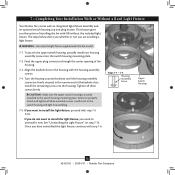
... the product. 7-7. Exceeding the wattage limit marked on the MAX wattage sticker affixed to the upper switch housing with US federal energy regulations, this ceiling fan contains a device that restricts its light output. 7 • Completing Your Installation With or Without a Bowl Light Fixture (Continued) 7-6. Place the lower switch housing assembly over...: Both plug connectors are properly aligned before connecting them. Plug Connector Detail Plug Connector Housing Assembly Screw 13 42453-01 • 03/04/11 • Hunter Fan Company
... the product. 7-7. Exceeding the wattage limit marked on the MAX wattage sticker affixed to the upper switch housing with US federal energy regulations, this ceiling fan contains a device that restricts its light output. 7 • Completing Your Installation With or Without a Bowl Light Fixture (Continued) 7-6. Place the lower switch housing assembly over...: Both plug connectors are properly aligned before connecting them. Plug Connector Detail Plug Connector Housing Assembly Screw 13 42453-01 • 03/04/11 • Hunter Fan Company

Owner's Manual
Page 14
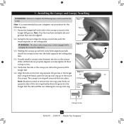
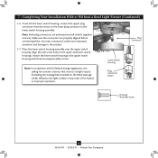
... breakaway connector on the end of the cover plate. 7-10. Align the holes in the center of the cover plate. 7-11. Thread the fan pull chain through the hole in the side of the glass bowl. Then, thread the light pull chain through the grommet hole in the center...(B10 Candelabra Base 60 Watt Maximum) Metal Rod Metal Disk Breakaway Connector Glass Bowl Cover Plate Finial 14 42453-01 • 03/04/11 • Hunter Fan Company Place the cover plate up against the glass bowl. 7 • Completing Your Installation With or Without a Bowl Light Fixture (Continued) Installing the ...
... breakaway connector on the end of the cover plate. 7-10. Align the holes in the center of the cover plate. 7-11. Thread the fan pull chain through the hole in the side of the glass bowl. Then, thread the light pull chain through the grommet hole in the center...(B10 Candelabra Base 60 Watt Maximum) Metal Rod Metal Disk Breakaway Connector Glass Bowl Cover Plate Finial 14 42453-01 • 03/04/11 • Hunter Fan Company Place the cover plate up against the glass bowl. 7 • Completing Your Installation With or Without a Bowl Light Fixture (Continued) Installing the ...

Owner's Manual
Page 15
... a white stripe. 7-16. Lower Switch Housing Male Dummy Terminal Female Dummy Terminal Cap Plug Button Step 7-21 15 42453-01 • 03/04/11 • Hunter Fan Company Install the switch housing cap and plug button to the lower switch housing. 7-22. Install the dummy terminals (included in the sack parts) on...
... a white stripe. 7-16. Lower Switch Housing Male Dummy Terminal Female Dummy Terminal Cap Plug Button Step 7-21 15 42453-01 • 03/04/11 • Hunter Fan Company Install the switch housing cap and plug button to the lower switch housing. 7-22. Install the dummy terminals (included in the sack parts) on...

Owner's Manual
Page 16
...; Pull the chain slowly to change settings. • Release slowly to the opposite position. Reversing Switch 16 42453-01 • 03/04/11 • Hunter Fan Company The fan pull chain controls power to cool the room with a furniture polishing cloth. A vacuum cleaner brush nozzle can remove heavier dust. Clean wood finish blades...
...; Pull the chain slowly to change settings. • Release slowly to the opposite position. Reversing Switch 16 42453-01 • 03/04/11 • Hunter Fan Company The fan pull chain controls power to cool the room with a furniture polishing cloth. A vacuum cleaner brush nozzle can remove heavier dust. Clean wood finish blades...
Owner's Manual
Page 17
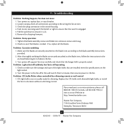
...according to the fan. Hunter Fan Company 7130 Goodlett Farms Parkway #400 Memphis, Tennessee 38016 17 42453-01 • 03/04/11 • Hunter Fan Company Check the plug connection in a location without a dimming control. Problem: Noisy operation 1. Problem: Lights shut off , support fan very carefully, and...6. Remove the shipping bumpers. Tighten the blade assembly screws and blade iron armature screws until snug. 2. Check to balance the fan. 3. Problem: Excessive wobbling 1. After thoroughly verifying the blades are not usually made for dimming. Check to make sure the wattage...
...according to the fan. Hunter Fan Company 7130 Goodlett Farms Parkway #400 Memphis, Tennessee 38016 17 42453-01 • 03/04/11 • Hunter Fan Company Check the plug connection in a location without a dimming control. Problem: Noisy operation 1. Problem: Lights shut off , support fan very carefully, and...6. Remove the shipping bumpers. Tighten the blade assembly screws and blade iron armature screws until snug. 2. Check to balance the fan. 3. Problem: Excessive wobbling 1. After thoroughly verifying the blades are not usually made for dimming. Check to make sure the wattage...
Parts Guide
Page 1
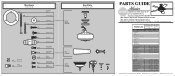
...01 08198-01 1 08200-01 08200-01 1 63756-18 63756-18 1 84602-02 84602-04 2 77646-04 77646-04 Hunter Fan Company • 7130 Goodlett Farms Pkwy. #400 • Memphis, TN 38016 • www.hunterfan.com • 98000... Grommet Screw, Switch Housing Assembly Screw, Machine, 6-32 Hanger Bracket Assembly Blade Assembly Switch Housing Assembly Fan Parts (Not Drawn to Scale) PARTS GUIDE Using this Parts Guide, make sure all parts are missing...Extension Globe/Shade Light bulb / Bulb Model # 20177 20178 Asm. If parts are included in the box. THIS PARTS GUIDE IS FOR REFERENCE ONLY.
...01 08198-01 1 08200-01 08200-01 1 63756-18 63756-18 1 84602-02 84602-04 2 77646-04 77646-04 Hunter Fan Company • 7130 Goodlett Farms Pkwy. #400 • Memphis, TN 38016 • www.hunterfan.com • 98000... Grommet Screw, Switch Housing Assembly Screw, Machine, 6-32 Hanger Bracket Assembly Blade Assembly Switch Housing Assembly Fan Parts (Not Drawn to Scale) PARTS GUIDE Using this Parts Guide, make sure all parts are missing...Extension Globe/Shade Light bulb / Bulb Model # 20177 20178 Asm. If parts are included in the box. THIS PARTS GUIDE IS FOR REFERENCE ONLY.


