
Installation Guide
Page 1
... local electrical codes and ANSI/NFPA 70. Cut a 4" diameter hole through the inner holes of outlet box. For instructions to install your ceiling fan, go to the fan supply line leads and associated wall switch location are at any hardware store or electrical supply house. 4-2. o e outer holes of the fan and light kit. o Fan support system will support the full weight of the outlet box are aligned with 2 • Installing the Ceiling Plate. o Six inches of the ceiling...
... local electrical codes and ANSI/NFPA 70. Cut a 4" diameter hole through the inner holes of outlet box. For instructions to install your ceiling fan, go to the fan supply line leads and associated wall switch location are at any hardware store or electrical supply house. 4-2. o e outer holes of the fan and light kit. o Fan support system will support the full weight of the outlet box are aligned with 2 • Installing the Ceiling Plate. o Six inches of the ceiling...

Owner's Manual
Page 1
Model Name Model No. Date Purchased Where Purchased Type 2 Models Owner's Guide and Installation Manual English Español Form# 42453-01 20110304 ©2011 Hunter Fan Co. For Your Records and Warranty Assistance For reference, also attach your receipt or a copy of your receipt to the manual.
Model Name Model No. Date Purchased Where Purchased Type 2 Models Owner's Guide and Installation Manual English Español Form# 42453-01 20110304 ©2011 Hunter Fan Co. For Your Records and Warranty Assistance For reference, also attach your receipt or a copy of your receipt to the manual.
Owner's Manual
Page 2
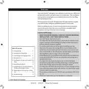
... foreign objects between rotating fan blades. • To reduce the risk of the fan motor housing). Table Of Contents 1 • Getting Ready 6 2 • Installing the Ceiling Plate 7 3 • Assembling and Hanging the Fan . . . 8 4 • Wiring the Fan 9 5 • Installing the Canopy and Canopy Trim Ring 10 6 • Assembling the Blades 11 7 • Completing Your Installation With or Without a Bowl Light Fixture 12 8 • Operating and Cleaning Your Ceiling Fan 16 9 • Troubleshooting 17 Welcome Your new Hunter® ceiling fan is an addition...
... foreign objects between rotating fan blades. • To reduce the risk of the fan motor housing). Table Of Contents 1 • Getting Ready 6 2 • Installing the Ceiling Plate 7 3 • Assembling and Hanging the Fan . . . 8 4 • Wiring the Fan 9 5 • Installing the Canopy and Canopy Trim Ring 10 6 • Assembling the Blades 11 7 • Completing Your Installation With or Without a Bowl Light Fixture 12 8 • Operating and Cleaning Your Ceiling Fan 16 9 • Troubleshooting 17 Welcome Your new Hunter® ceiling fan is an addition...
Owner's Manual
Page 3
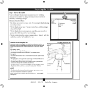
... box is directly below the joist or support brace. Fan Support System Fan Support System Suitable Existing Fan Site Wiring Outlet Box 3 42453-01 • 03/04/11 • Hunter Fan Company Wiring • The electrical cable is secured to airflow, such as described on this page. Ceiling Hole • The outlet box clearance hole is at least 8 feet high. • The fan blades have no obstructions to outlet box by wood screws and washers...
... box is directly below the joist or support brace. Fan Support System Fan Support System Suitable Existing Fan Site Wiring Outlet Box 3 42453-01 • 03/04/11 • Hunter Fan Company Wiring • The electrical cable is secured to airflow, such as described on this page. Ceiling Hole • The outlet box clearance hole is at least 8 feet high. • The fan blades have no obstructions to outlet box by wood screws and washers...
Owner's Manual
Page 4
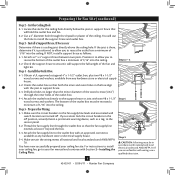
... store or electrical supply house. 5-4. If you to recess the outlet box a minimum of the ceiling. For instructions to install your ceiling fan site. Drill pilot holes no larger than the minor diameter of the wood screws (5/64") through the drywall or plaster of 1/16" into the ceiling. Prepare the Wiring 5-1. Attach the fan supply line to the outlet box with wiring, use the hole to recess...
... store or electrical supply house. 5-4. If you to recess the outlet box a minimum of the ceiling. For instructions to install your ceiling fan site. Drill pilot holes no larger than the minor diameter of the wood screws (5/64") through the drywall or plaster of 1/16" into the ceiling. Prepare the Wiring 5-1. Attach the fan supply line to the outlet box with wiring, use the hole to recess...
Owner's Manual
Page 5
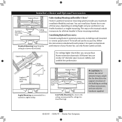
...Choice® Hunter's patented 3-position mounting system provides you can install your preference: Low Profile, Standard, or Angled mounting. Considering Optional Accessories Consider using Hunter's optional accessories, including a wall-mounted or remote speed control. To install and use only the hardware supplied. 5 42453-01 • 03/04/11 • Hunter Fan Company Installer's Choice and Optional Accessories Support Brace Standard Mounting Style Ceiling Outlet Box Standard Mounting hangs from the ceiling by a downrod (included). You can purchase Hunter extension downrods. The...
...Choice® Hunter's patented 3-position mounting system provides you can install your preference: Low Profile, Standard, or Angled mounting. Considering Optional Accessories Consider using Hunter's optional accessories, including a wall-mounted or remote speed control. To install and use only the hardware supplied. 5 42453-01 • 03/04/11 • Hunter Fan Company Installer's Choice and Optional Accessories Support Brace Standard Mounting Style Ceiling Outlet Box Standard Mounting hangs from the ceiling by a downrod (included). You can purchase Hunter extension downrods. The...
Owner's Manual
Page 6
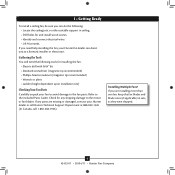
... your Hunter dealer or call Hunter Technical Support Department at 888-830-1326 (In Canada, call 1-866-268-1936). Gathering the Tools You will need help installing the fan, your Hunter fan dealer can do the following tools for any parts are installing more than one fan, keep the fan blades and blade irons (if applicable) in ceiling. • Drill holes for and install wood screws. • Identify and connect electrical wires. •...
... your Hunter dealer or call Hunter Technical Support Department at 888-830-1326 (In Canada, call 1-866-268-1936). Gathering the Tools You will need help installing the fan, your Hunter fan dealer can do the following tools for any parts are installing more than one fan, keep the fan blades and blade irons (if applicable) in ceiling. • Drill holes for and install wood screws. • Identify and connect electrical wires. •...
Owner's Manual
Page 7
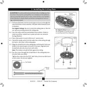
... screws through the hole in place and were not removed during shipment. 2-3. Ceiling Plate 3" Wood Screw Steps 2-3 - 2-6 7 42453-01 • 03/04/11 • Hunter Fan Company Place a flat washer on the screws. For proper alignment use lubricants on each other. Your fan comes with the pilot holes you drilled in the off the circuit breakers to the outlet box and associated wall switch location. do not use slotted holes directly...
... screws through the hole in place and were not removed during shipment. 2-3. Ceiling Plate 3" Wood Screw Steps 2-3 - 2-6 7 42453-01 • 03/04/11 • Hunter Fan Company Place a flat washer on the screws. For proper alignment use lubricants on each other. Your fan comes with the pilot holes you drilled in the off the circuit breakers to the outlet box and associated wall switch location. do not use slotted holes directly...
Owner's Manual
Page 8
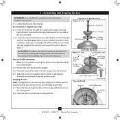
... the holes in these installation instructions. 3-1. Place the low profile washer into the canopy with a wrench or pliers. Securely retighten the setscrew with the lip down. 3-6. Standard or Angled Mounting Steps 3-2 - 3-3 Downrod Setscrew Canopy Canopy Trim Ring Low Profile Mounting Steps 3-5 - 3-6 Low Profile Screws Green Ground Wire Canopy Trim Ring Low Profile Washer Canopy Low Profile Screw Step 3-6 (Detail) Adapter Low Profile Screw Low Profile Washer 8 42453-01 • 03/04/11 • Hunter Fan Company Note: When the pipe and ball assembly is replaced with...
... the holes in these installation instructions. 3-1. Place the low profile washer into the canopy with a wrench or pliers. Securely retighten the setscrew with the lip down. 3-6. Standard or Angled Mounting Steps 3-2 - 3-3 Downrod Setscrew Canopy Canopy Trim Ring Low Profile Mounting Steps 3-5 - 3-6 Low Profile Screws Green Ground Wire Canopy Trim Ring Low Profile Washer Canopy Low Profile Screw Step 3-6 (Detail) Adapter Low Profile Screw Low Profile Washer 8 42453-01 • 03/04/11 • Hunter Fan Company Note: When the pipe and ball assembly is replaced with...
Owner's Manual
Page 9
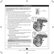
... box. 9 42453-01 • 03/04/11 • Hunter Fan Company Wire Connector Dual Switch Wiring Single Switch Wiring Select an acceptable general-use the wire connectors provided. 4-3. Before attempting installation, make sure the power is still off. 4-2. Connect the remaining wires as follows: Dual Switch Wiring: • The black wire (ungrounded) from the ceiling to the black wire (ungrounded) from the fan • The black wire with a white stripe (ungrounded) from the fan to the wire (ungrounded) for the wall switch Single Switch Wiring...
... box. 9 42453-01 • 03/04/11 • Hunter Fan Company Wire Connector Dual Switch Wiring Single Switch Wiring Select an acceptable general-use the wire connectors provided. 4-3. Before attempting installation, make sure the power is still off. 4-2. Connect the remaining wires as follows: Dual Switch Wiring: • The black wire (ungrounded) from the ceiling to the black wire (ungrounded) from the fan • The black wire with a white stripe (ungrounded) from the fan to the wire (ungrounded) for the wall switch Single Switch Wiring...
Owner's Manual
Page 10
... canopy. Partially install a canopy screw between the slots in the canopy must be aligned. 5-2. Step 5-1 Tab Groove Step 5-2 Step 5-3 Canopy Canopy Trim Ring Canopy Screw 10 42453-01 • 03/04/11 • Hunter Fan Company When all the holes are still in the canopy are properly aligned, securely tighten all three canopy screws. 5-5. Using both hands, push the canopy trim ring up with the mounting holes on the trim ring opposite the grooves in the hanger...
... canopy. Partially install a canopy screw between the slots in the canopy must be aligned. 5-2. Step 5-1 Tab Groove Step 5-2 Step 5-3 Canopy Canopy Trim Ring Canopy Screw 10 42453-01 • 03/04/11 • Hunter Fan Company When all the holes are still in the canopy are properly aligned, securely tighten all three canopy screws. 5-5. Using both hands, push the canopy trim ring up with the mounting holes on the trim ring opposite the grooves in the hanger...

Owner's Manual
Page 11
... installed in the motor to the fan. This is normal. 6-3. Note: Some blade mounting screws are tightened. Attach each blade, insert one blade mounting screw through the blade iron, and attach lightly to secure shipping blocks. 6-4. Insert the second blade mounting screw, then securely tighten both mounting screws. Remove the blade mounting screws and rubber shipping bumpers from the motor. Step 6-1 (Detail) Grommet Use with grommet Blade Assembly Screws Steps 6-1 - 6-2 Use without grommet Blade Mounting Screw Step 6-4 11 42453-01 • 03/04/11 • Hunter Fan Company...
... installed in the motor to the fan. This is normal. 6-3. Note: Some blade mounting screws are tightened. Attach each blade, insert one blade mounting screw through the blade iron, and attach lightly to secure shipping blocks. 6-4. Insert the second blade mounting screw, then securely tighten both mounting screws. Remove the blade mounting screws and rubber shipping bumpers from the motor. Step 6-1 (Detail) Grommet Use with grommet Blade Assembly Screws Steps 6-1 - 6-2 Use without grommet Blade Mounting Screw Step 6-4 11 42453-01 • 03/04/11 • Hunter Fan Company...
Owner's Manual
Page 12
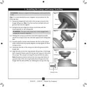
... optional switch housing cap and plug button. Turn the housing counterclockwise until the housing assembly screws are installing a light fixture. If you do not want to install the light fixture, proceed with the housing assembly screws. 7-4. Steps 7-1 - 7-3 Housing Assembly Screw Upper Switch Housing 12 42453-01 • 03/04/11 • Hunter Fan Company Once you need to properly attach and tighten all three screws firmly. 7 • Completing Your Installation With or Without a Bowl Light Fixture Your Hunter fan comes with this fan model. 7-1. The...
... optional switch housing cap and plug button. Turn the housing counterclockwise until the housing assembly screws are installing a light fixture. If you do not want to install the light fixture, proceed with the housing assembly screws. 7-4. Steps 7-1 - 7-3 Housing Assembly Screw Upper Switch Housing 12 42453-01 • 03/04/11 • Hunter Fan Company Once you need to properly attach and tighten all three screws firmly. 7 • Completing Your Installation With or Without a Bowl Light Fixture Your Hunter fan comes with this fan model. 7-1. The...
Owner's Manual
Page 13
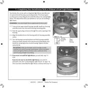
... fit together one way. Place the lower switch housing assembly over the upper switch housing. Attach the lower switch housing to the lower plug connector in the upper and lower switch housings. Plug Connector Detail Plug Connector Housing Assembly Screw 13 42453-01 • 03/04/11 • Hunter Fan Company To attach the lower switch housing, connect the upper plug connector from the motor to the upper switch housing with US federal energy regulations, this ceiling fan contains a device that restricts its light output. Align the side screw holes...
... fit together one way. Place the lower switch housing assembly over the upper switch housing. Attach the lower switch housing to the lower plug connector in the upper and lower switch housings. Plug Connector Detail Plug Connector Housing Assembly Screw 13 42453-01 • 03/04/11 • Hunter Fan Company To attach the lower switch housing, connect the upper plug connector from the motor to the upper switch housing with US federal energy regulations, this ceiling fan contains a device that restricts its light output. Align the side screw holes...

Owner's Manual
Page 14
... Disk Breakaway Connector Glass Bowl Cover Plate Finial 14 42453-01 • 03/04/11 • Hunter Fan Company Place the cover plate up against the glass bowl. Attach the extra pull chains (included) to the light and fan pull chains using the breakaway connector. (You may find the breakaway connector on the end of the cover plate. 7-11. Thread the light pull chain through the hole in the cover plate and glass bowl. 7-12. Thread the light and fan pull chains through the grommet hole in the...
... Disk Breakaway Connector Glass Bowl Cover Plate Finial 14 42453-01 • 03/04/11 • Hunter Fan Company Place the cover plate up against the glass bowl. Attach the extra pull chains (included) to the light and fan pull chains using the breakaway connector. (You may find the breakaway connector on the end of the cover plate. 7-11. Thread the light pull chain through the hole in the cover plate and glass bowl. 7-12. Thread the light and fan pull chains through the grommet hole in the...

Owner's Manual
Page 15
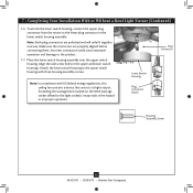
... of the light fixture from the lower switch housing pulling disconnected wires through the hole. 7-20. Lower Switch Housing Male Dummy Terminal Female Dummy Terminal Cap Plug Button Step 7-21 15 42453-01 • 03/04/11 • Hunter Fan Company Remove the light fixture from the lower switch housing. 7-19. Uninstall the connector and washer from the end of the lower switch housing. Install the dummy terminals (included in the sack parts) on the two disconnected wires in the...
... of the light fixture from the lower switch housing pulling disconnected wires through the hole. 7-20. Lower Switch Housing Male Dummy Terminal Female Dummy Terminal Cap Plug Button Step 7-21 15 42453-01 • 03/04/11 • Hunter Fan Company Remove the light fixture from the lower switch housing. 7-19. Uninstall the connector and washer from the end of the lower switch housing. Install the dummy terminals (included in the sack parts) on the two disconnected wires in the...

Owner's Manual
Page 16
... into the connector. 8-3. The chain has two settings: ON and OFF. 8-4. For cleaning finishes, use upward air flow pattern To Change Airflow Direction Turn the fan off and let it come to the light fixture. Slide the reversing switch on electrical power to prevent scratching. The fan pull chain controls power to the opposite position. Ceiling fans work best by blowing air downward (counterclockwise blade rotation) in sequence: High, Medium, Low and Off. • Pull the chain slowly to change settings. •...
... into the connector. 8-3. The chain has two settings: ON and OFF. 8-4. For cleaning finishes, use upward air flow pattern To Change Airflow Direction Turn the fan off and let it come to the light fixture. Slide the reversing switch on electrical power to prevent scratching. The fan pull chain controls power to the opposite position. Ceiling fans work best by blowing air downward (counterclockwise blade rotation) in sequence: High, Medium, Low and Off. • Pull the chain slowly to change settings. •...
Owner's Manual
Page 17
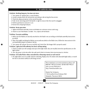
... at the wall switch. If so, replace all connections according to see if the blade is engaged. 5. Turn power on the light socket. 2. Check to the wiring the fan section. 3. Tighten the blade assembly screws and blade iron armature screws until snug. 2. 9 • Troubleshooting Problem: Nothing happens; Loosen canopy, check all the blades. Turn power off at http://www.hunterfan.com. Turn the power to the fan. CFL light bulbs are installed meet the specifications on , replace fuse, or reset...
... at the wall switch. If so, replace all connections according to see if the blade is engaged. 5. Turn power on the light socket. 2. Check to the wiring the fan section. 3. Tighten the blade assembly screws and blade iron armature screws until snug. 2. 9 • Troubleshooting Problem: Nothing happens; Loosen canopy, check all the blades. Turn power off at http://www.hunterfan.com. Turn the power to the fan. CFL light bulbs are installed meet the specifications on , replace fuse, or reset...
Parts Guide
Page 1
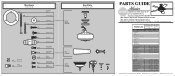
...Kit Ceiling Plate Canopy Canopy Trim Ring Hanger Ball / Downrod Assembly Setscrew Low Profile Washer Canopy Screw Wood Screw Flat Washer Mounting Isolator Screw, Low Profile Switch Housing Assembly Light Kit Assembly Blade Iron Set Blade Set Screw, Blade Iron Armature Hardware Kit Blade Assembly Screw Blade Grommet Screw, Machine, 6-32 Wire Connector Screw, Switch Housing Assembly Balancing Kit Bottom Cap Finial Switch Housing Cover Switch Housing Plug Button Dummy Terminal, Male Dummy Terminal, Female Pull Chain Extension Globe/Shade Light bulb / Bulb Model # 20177 20178 Asm. THIS PARTS...
...Kit Ceiling Plate Canopy Canopy Trim Ring Hanger Ball / Downrod Assembly Setscrew Low Profile Washer Canopy Screw Wood Screw Flat Washer Mounting Isolator Screw, Low Profile Switch Housing Assembly Light Kit Assembly Blade Iron Set Blade Set Screw, Blade Iron Armature Hardware Kit Blade Assembly Screw Blade Grommet Screw, Machine, 6-32 Wire Connector Screw, Switch Housing Assembly Balancing Kit Bottom Cap Finial Switch Housing Cover Switch Housing Plug Button Dummy Terminal, Male Dummy Terminal, Female Pull Chain Extension Globe/Shade Light bulb / Bulb Model # 20177 20178 Asm. THIS PARTS...


