
Installation Guide
Page 1
... new Hunter fan. If you to the outlet box with the rotating fan blades during normal operation. • e fan blades are essential for Existing Fan Site If you to the fan supply line leads and associated wall switch location are aligned with national and local electrical codes and ANSI/NFPA 70. Steps 2 - 3 Step 3 Install a Support Brace, If Necessary Determine if there is a ceiling joist directly above the floor and the ceiling...
... new Hunter fan. If you to the outlet box with the rotating fan blades during normal operation. • e fan blades are essential for Existing Fan Site If you to the fan supply line leads and associated wall switch location are aligned with national and local electrical codes and ANSI/NFPA 70. Steps 2 - 3 Step 3 Install a Support Brace, If Necessary Determine if there is a ceiling joist directly above the floor and the ceiling...

Owner's Manual
Page 1
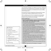
Date Purchased Where Purchased Type 2 Models Owner's Guide and Installation Manual English Español Form# 42453-01 20110304 ©2011 Hunter Fan Co. Model Name Model No. For Your Records and Warranty Assistance For reference, also attach your receipt or a copy of your receipt to the manual.
Date Purchased Where Purchased Type 2 Models Owner's Guide and Installation Manual English Español Form# 42453-01 20110304 ©2011 Hunter Fan Co. Model Name Model No. For Your Records and Warranty Assistance For reference, also attach your receipt or a copy of your receipt to the manual.
Owner's Manual
Page 2
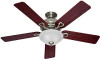
...; Getting Ready 6 2 • Installing the Ceiling Plate 7 3 • Assembling and Hanging the Fan . . . 8 4 • Wiring the Fan 9 5 • Installing the Canopy and Canopy Trim Ring 10 6 • Assembling the Blades 11 7 • Completing Your Installation With or Without a Bowl Light Fixture 12 8 • Operating and Cleaning Your Ceiling Fan 16 9 • Troubleshooting 17 Welcome Your new Hunter® ceiling fan is complete. © 2011 Hunter Fan Company 2 42453-01 • 03/04/11 • Hunter Fan Company If you complete instructions for many years. Never...
...; Getting Ready 6 2 • Installing the Ceiling Plate 7 3 • Assembling and Hanging the Fan . . . 8 4 • Wiring the Fan 9 5 • Installing the Canopy and Canopy Trim Ring 10 6 • Assembling the Blades 11 7 • Completing Your Installation With or Without a Bowl Light Fixture 12 8 • Operating and Cleaning Your Ceiling Fan 16 9 • Troubleshooting 17 Welcome Your new Hunter® ceiling fan is complete. © 2011 Hunter Fan Company 2 42453-01 • 03/04/11 • Hunter Fan Company If you complete instructions for many years. Never...
Owner's Manual
Page 3
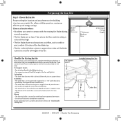
... directly to Floor 8' Minimum Ceiling Height Checklist for Existing Fan Site If you cannot check off every item, prepare a new fan site as walls or posts, within 30 inches of lead wires extend from outlet box. Choose the Fan Site Proper ceiling fan location and attachment to the building structure are at least 8 feet high. • The fan blades have no obstructions to outlet box by wood screws and washers...
... directly to Floor 8' Minimum Ceiling Height Checklist for Existing Fan Site If you cannot check off every item, prepare a new fan site as walls or posts, within 30 inches of lead wires extend from outlet box. Choose the Fan Site Proper ceiling fan location and attachment to the building structure are at least 8 feet high. • The fan blades have no obstructions to outlet box by wood screws and washers...
Owner's Manual
Page 4
... in the off . For instructions to install your ceiling fan, go to ensure it to allow you to the outlet box with two #8 x 1-1/2" Step 4 wood screws and washers. Prepare the Wiring 5-1. You have now successfully prepared your fan manual and continue with national and local electrical codes and ANSI/NFPA 70. Cut the Ceiling Hole 2-1. Check the support brace to your ceiling fan site. Step 5 - Obtain a UL...
... in the off . For instructions to install your ceiling fan, go to ensure it to allow you to the outlet box with two #8 x 1-1/2" Step 4 wood screws and washers. Prepare the Wiring 5-1. You have now successfully prepared your fan manual and continue with national and local electrical codes and ANSI/NFPA 70. Cut the Ceiling Hole 2-1. Check the support brace to your ceiling fan site. Step 5 - Obtain a UL...
Owner's Manual
Page 5
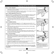
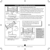
...for a vaulted or angled ceiling Support Brace Low Profile Mounting Style Ceiling Outlet Box Low Profile Mounting fits close to the ceiling, recommended for all three Installer's Choice mounting methods. All Hunter fans use sturdy 3/4" diameter pipe to these instructions, and use only the hardware supplied. 5 42453-01 • 03/04/11 • Hunter Fan Company Considering Optional Accessories Consider using Hunter's optional accessories, including a wall-mounted or remote speed control. Support Brace Ceiling Outlet Box For ceilings higher than 8 feet high CAUTION: To reduce...
...for a vaulted or angled ceiling Support Brace Low Profile Mounting Style Ceiling Outlet Box Low Profile Mounting fits close to the ceiling, recommended for all three Installer's Choice mounting methods. All Hunter fans use sturdy 3/4" diameter pipe to these instructions, and use only the hardware supplied. 5 42453-01 • 03/04/11 • Hunter Fan Company Considering Optional Accessories Consider using Hunter's optional accessories, including a wall-mounted or remote speed control. Support Brace Ceiling Outlet Box For ceilings higher than 8 feet high CAUTION: To reduce...
Owner's Manual
Page 6
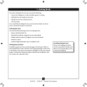
Refer to the fan parts. Check for any parts are installing more than one fan, keep the fan blades and blade irons (if applicable) in ceiling. • Drill holes for and install wood screws. • Identify and connect electrical wires. • Lift 40 pounds. If any shipping damage to the motor or fan blades. 1 • Getting Ready To install a ceiling fan, be sure you can do the following tools for installing the fan: • Electric drill with...
Refer to the fan parts. Check for any parts are installing more than one fan, keep the fan blades and blade irons (if applicable) in ceiling. • Drill holes for and install wood screws. • Identify and connect electrical wires. • Lift 40 pounds. If any shipping damage to the motor or fan blades. 1 • Getting Ready To install a ceiling fan, be sure you can do the following tools for installing the fan: • Electric drill with...
Owner's Manual
Page 7
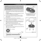
... supply wires from each of the ceiling plate. 2-5. Pass the screws through the outermost holes in the ceiling plate with four preinstalled noise isolators. Ceiling Plate 3" Wood Screw Steps 2-3 - 2-6 7 42453-01 • 03/04/11 • Hunter Fan Company Align the slotted holes in the outlet box. Your fan comes with the pilot holes you drilled in place and were not removed during shipment. 2-3. Place a flat washer on the screws. Tighten the screws...
... supply wires from each of the ceiling plate. 2-5. Pass the screws through the outermost holes in the ceiling plate with four preinstalled noise isolators. Ceiling Plate 3" Wood Screw Steps 2-3 - 2-6 7 42453-01 • 03/04/11 • Hunter Fan Company Align the slotted holes in the outlet box. Your fan comes with the pilot holes you drilled in place and were not removed during shipment. 2-3. Place a flat washer on the screws. Tighten the screws...
Owner's Manual
Page 8
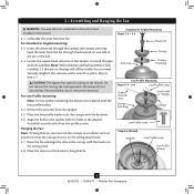
...side of the pin in these installation instructions. 3-1. Once assembled, do not remove the downrod. Align the holes in the washer with a wrench or pliers. Place the slots over the hooks to step 3-7. Standard or Angled Mounting Steps 3-2 - 3-3 Downrod Setscrew Canopy Canopy Trim Ring Low Profile Mounting Steps 3-5 - 3-6 Low Profile Screws Green Ground Wire Canopy Trim Ring Low Profile Washer Canopy Low Profile Screw Step 3-6 (Detail) Adapter Low Profile Screw Low Profile Washer 8 42453-01 • 03/04/11 • Hunter Fan Company Loosen the square head setscrew...
...side of the pin in these installation instructions. 3-1. Once assembled, do not remove the downrod. Align the holes in the washer with a wrench or pliers. Place the slots over the hooks to step 3-7. Standard or Angled Mounting Steps 3-2 - 3-3 Downrod Setscrew Canopy Canopy Trim Ring Low Profile Mounting Steps 3-5 - 3-6 Low Profile Screws Green Ground Wire Canopy Trim Ring Low Profile Washer Canopy Low Profile Screw Step 3-6 (Detail) Adapter Low Profile Screw Low Profile Washer 8 42453-01 • 03/04/11 • Hunter Fan Company Loosen the square head setscrew...
Owner's Manual
Page 9
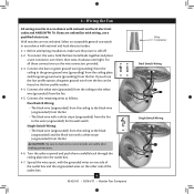
... and local electrical codes. 4-1. Connect the white wire (grounded) from the ceiling to the white wire (grounded) from the fan. Turn the splices upward and push them , then twist clockwise until tight. Wall switches are unfamiliar with the grounded wires on one side of the outlet box. 9 42453-01 • 03/04/11 • Hunter Fan Company Wire Connector Dual Switch Wiring Single Switch Wiring Before attempting installation, make sure the power is...
... and local electrical codes. 4-1. Connect the white wire (grounded) from the ceiling to the white wire (grounded) from the fan. Turn the splices upward and push them , then twist clockwise until tight. Wall switches are unfamiliar with the grounded wires on one side of the outlet box. 9 42453-01 • 03/04/11 • Hunter Fan Company Wire Connector Dual Switch Wiring Single Switch Wiring Before attempting installation, make sure the power is...
Owner's Manual
Page 10
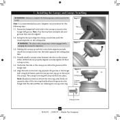
...; Hunter Fan Company Note: It is secure in the canopy. Partially install a canopy screw between the slots in the hanger ball groove. Swing the fan up to remove the trim ring, press firmly on opposite sides of the trim ring directly above the groove in the grooves of the canopy. WARNING: The slots in the hanger ball. Using both hands, push the canopy trim ring up with the mounting holes on the trim ring opposite...
...; Hunter Fan Company Note: It is secure in the canopy. Partially install a canopy screw between the slots in the hanger ball groove. Swing the fan up to remove the trim ring, press firmly on opposite sides of the trim ring directly above the groove in the grooves of the canopy. WARNING: The slots in the hanger ball. Using both hands, push the canopy trim ring up with the mounting holes on the trim ring opposite...

Owner's Manual
Page 11
...) Grommet Use with grommet Blade Assembly Screws Steps 6-1 - 6-2 Use without grommet Blade Mounting Screw Step 6-4 11 42453-01 • 03/04/11 • Hunter Fan Company 6 • Assembling the Blades Hunter fans use several styles of fan blade irons (brackets that hold the blade to secure shipping blocks. 6-4. If your fan has grommets, insert them by hand into the holes on the blades. 6-2. Your fan may appear slightly loose after screws are installed in the motor to the fan). 6-1. Remove the blade mounting screws and rubber shipping bumpers from the motor. This...
...) Grommet Use with grommet Blade Assembly Screws Steps 6-1 - 6-2 Use without grommet Blade Mounting Screw Step 6-4 11 42453-01 • 03/04/11 • Hunter Fan Company 6 • Assembling the Blades Hunter fans use several styles of fan blade irons (brackets that hold the blade to secure shipping blocks. 6-4. If your fan has grommets, insert them by hand into the holes on the blades. 6-2. Your fan may appear slightly loose after screws are installed in the motor to the fan). 6-1. Remove the blade mounting screws and rubber shipping bumpers from the motor. This...
Owner's Manual
Page 12
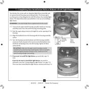
... • 03/04/11 • Hunter Fan Company Feed the upper plug connector through the center opening of installing the fan with the housing assembly screws. 7-4. Align the keyhole slots in the switch housing and light fixture falling. 7-5. Install the remaining screw into the switch housing mounting plate. 7-2. To attach the upper switch housing, partially install two housing assembly screws into the housing. Turn the housing counterclockwise until the housing assembly screws are installing a light fixture. The steps below direct you whether or not you...
... • 03/04/11 • Hunter Fan Company Feed the upper plug connector through the center opening of installing the fan with the housing assembly screws. 7-4. Align the keyhole slots in the switch housing and light fixture falling. 7-5. Install the remaining screw into the switch housing mounting plate. 7-2. To attach the upper switch housing, partially install two housing assembly screws into the housing. Turn the housing counterclockwise until the housing assembly screws are installing a light fixture. The steps below direct you whether or not you...
Owner's Manual
Page 13
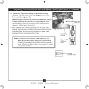
...Plug Connector Detail Plug Connector Housing Assembly Screw 13 42453-01 • 03/04/11 • Hunter Fan Company Attach the lower switch housing to the product. 7-7. Steps 7-6 - 7-7 Lower Switch Housing Note: In compliance with three housing assembly screws. Exceeding the wattage limit marked on the MAX wattage sticker affixed to the lower plug connector in the lower switch housing assembly. 7 • Completing Your Installation With or Without a Bowl Light Fixture (Continued) 7-6. To attach the lower switch housing, connect the upper plug connector from the motor...
...Plug Connector Detail Plug Connector Housing Assembly Screw 13 42453-01 • 03/04/11 • Hunter Fan Company Attach the lower switch housing to the product. 7-7. Steps 7-6 - 7-7 Lower Switch Housing Note: In compliance with three housing assembly screws. Exceeding the wattage limit marked on the MAX wattage sticker affixed to the lower plug connector in the lower switch housing assembly. 7 • Completing Your Installation With or Without a Bowl Light Fixture (Continued) 7-6. To attach the lower switch housing, connect the upper plug connector from the motor...

Owner's Manual
Page 14
... glass bowl. Align the holes in the center of the extra chain.) Light Bulbs (B10 Candelabra Base 60 Watt Maximum) Metal Rod Metal Disk Breakaway Connector Glass Bowl Cover Plate Finial 14 42453-01 • 03/04/11 • Hunter Fan Company 7 • Completing Your Installation With or Without a Bowl Light Fixture (Continued) Installing the Glass Bowl 7-8. First install B10 candelabra bulbs (60 Watt Maximum) into the sockets. 7-9. Then, thread the light pull chain through the finial and screw...
... glass bowl. Align the holes in the center of the extra chain.) Light Bulbs (B10 Candelabra Base 60 Watt Maximum) Metal Rod Metal Disk Breakaway Connector Glass Bowl Cover Plate Finial 14 42453-01 • 03/04/11 • Hunter Fan Company 7 • Completing Your Installation With or Without a Bowl Light Fixture (Continued) Installing the Glass Bowl 7-8. First install B10 candelabra bulbs (60 Watt Maximum) into the sockets. 7-9. Then, thread the light pull chain through the finial and screw...

Owner's Manual
Page 15
... Dummy Terminal Cap Plug Button Step 7-21 15 42453-01 • 03/04/11 • Hunter Fan Company Threaded Rod Note: When removing the wires, pull the thin plug connector (male) through first, and then pull the other plug connector (female) through the hole in the lower switch housing. 7-21. Once you have uninstalled the light fixture, continue with a white stripe. 7-16. Uninstall the connector and washer from the lower switch housing. 7-19. Install the...
... Dummy Terminal Cap Plug Button Step 7-21 15 42453-01 • 03/04/11 • Hunter Fan Company Threaded Rod Note: When removing the wires, pull the thin plug connector (male) through first, and then pull the other plug connector (female) through the hole in the lower switch housing. 7-21. Once you have uninstalled the light fixture, continue with a white stripe. 7-16. Uninstall the connector and washer from the lower switch housing. 7-19. Install the...

Owner's Manual
Page 16
... finish blades with a direct breeze. Slide the reversing switch on electrical power to a complete stop. For cleaning finishes, use upward air flow pattern To Change Airflow Direction Turn the fan off and let it come to the fan. 8-2. You may use an artistic agent, but never abrasive cleaning agents as the fan finish. Ceiling fans work best by blowing air downward (counterclockwise blade rotation) in sequence: High, Medium, Low and Off. • Pull the chain slowly to change settings...
... finish blades with a direct breeze. Slide the reversing switch on electrical power to a complete stop. For cleaning finishes, use upward air flow pattern To Change Airflow Direction Turn the fan off and let it come to the fan. 8-2. You may use an artistic agent, but never abrasive cleaning agents as the fan finish. Ceiling fans work best by blowing air downward (counterclockwise blade rotation) in sequence: High, Medium, Low and Off. • Pull the chain slowly to change settings...
Owner's Manual
Page 17
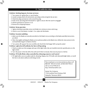
... remote or wall control 1. fan does not move 1. Problem: Noisy operation 1. Turn the power to make sure the wattage and type of the light bulbs that are not usually made for dimming. After thoroughly verifying the blades are securely attached to the blade irons according to ensure it is on the light socket. 2. Loosen canopy, check all the blades. Pull the pull chain to the blade assembly instructions provided. 2. Replace the CFL bulbs with dimmable light bulbs, or install...
... remote or wall control 1. fan does not move 1. Problem: Noisy operation 1. Turn the power to make sure the wattage and type of the light bulbs that are not usually made for dimming. After thoroughly verifying the blades are securely attached to the blade irons according to ensure it is on the light socket. 2. Loosen canopy, check all the blades. Pull the pull chain to the blade assembly instructions provided. 2. Replace the CFL bulbs with dimmable light bulbs, or install...
Parts Guide
Page 1
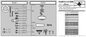
Parts List Item Name Hanging System Kit Ceiling Plate Canopy Canopy Trim Ring Hanger Ball / Downrod Assembly Setscrew Low Profile Washer Canopy Screw Wood Screw Flat Washer Mounting Isolator Screw, Low Profile Switch Housing Assembly Light Kit Assembly Blade Iron Set Blade Set Screw, Blade Iron Armature Hardware Kit Blade Assembly Screw Blade Grommet Screw, Machine, 6-32 Wire Connector Screw, Switch Housing Assembly Balancing Kit Bottom Cap Finial Switch Housing Cover Switch Housing Plug Button Dummy Terminal, Male Dummy Terminal, Female Pull Chain Extension Globe/Shade Light bulb / Bulb ...
Parts List Item Name Hanging System Kit Ceiling Plate Canopy Canopy Trim Ring Hanger Ball / Downrod Assembly Setscrew Low Profile Washer Canopy Screw Wood Screw Flat Washer Mounting Isolator Screw, Low Profile Switch Housing Assembly Light Kit Assembly Blade Iron Set Blade Set Screw, Blade Iron Armature Hardware Kit Blade Assembly Screw Blade Grommet Screw, Machine, 6-32 Wire Connector Screw, Switch Housing Assembly Balancing Kit Bottom Cap Finial Switch Housing Cover Switch Housing Plug Button Dummy Terminal, Male Dummy Terminal, Female Pull Chain Extension Globe/Shade Light bulb / Bulb ...
Parts Guide
Page 1
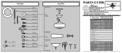
....hunterfan.com • 98000-01-949 10-29-2008 • ©2008 Parts List Item Name Hanger Bracket Assembly Model # Asm. Hardware (Drawn to Scale) x 1 x 2 x 4 x 2 x 3 x 2 x 1 x 2 Balancing x 1 Kit Wire x 4 Connector x 11 x 16 x 16 x 3 x 3 Low Profile Washer 3" Wood Screw Flat Washer 1.5" Wood Screw Locking Screw Canopy Screw Setscrew Mounting Isolator Screw, Blade Iron Armature Screw, Blade Assembly Blade Grommet Screw, Switch Housing Assembly Screw, Machine, 6-32 Hanger Bracket Assembly Blade Assembly Switch Housing Assembly Fan Parts (Not Drawn to Scale) PARTS GUIDE Using...
....hunterfan.com • 98000-01-949 10-29-2008 • ©2008 Parts List Item Name Hanger Bracket Assembly Model # Asm. Hardware (Drawn to Scale) x 1 x 2 x 4 x 2 x 3 x 2 x 1 x 2 Balancing x 1 Kit Wire x 4 Connector x 11 x 16 x 16 x 3 x 3 Low Profile Washer 3" Wood Screw Flat Washer 1.5" Wood Screw Locking Screw Canopy Screw Setscrew Mounting Isolator Screw, Blade Iron Armature Screw, Blade Assembly Blade Grommet Screw, Switch Housing Assembly Screw, Machine, 6-32 Hanger Bracket Assembly Blade Assembly Switch Housing Assembly Fan Parts (Not Drawn to Scale) PARTS GUIDE Using...


