Installation Instructions
Page 1
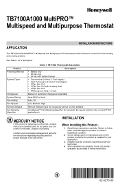
Read these instructions. 62-0273-05 TB7100A Thermostat Description. Check ratings given in instructions and on the product to ensure the product is replacing a control that contains ...suitable for automatic fan speed selection (fan coil and PTAC applications) MERCURY NOTICE If this Product... 1. TB7100A1000 MultiPRO™ Multispeed and Multipurpose Thermostat APPLICATION INSTALLATION INSTRUCTIONS The TB7100A1000 MultiPRO™ Multispeed and Multipurpose Thermostat provides electronic control of an old control. Description • Battery only • 24 Vac only •...
Read these instructions. 62-0273-05 TB7100A Thermostat Description. Check ratings given in instructions and on the product to ensure the product is replacing a control that contains ...suitable for automatic fan speed selection (fan coil and PTAC applications) MERCURY NOTICE If this Product... 1. TB7100A1000 MultiPRO™ Multispeed and Multipurpose Thermostat APPLICATION INSTALLATION INSTRUCTIONS The TB7100A1000 MultiPRO™ Multispeed and Multipurpose Thermostat provides electronic control of an old control. Description • Battery only • 24 Vac only •...
Installation Instructions
Page 2
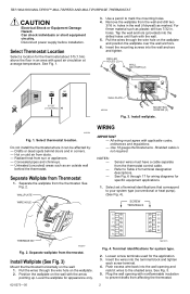
...to your system type (conventional or heat pump). (See Fig. 4). Drafts or dead spots behind the thermostat. Separate the wallplate from Thermostat 1. Sensor wires must agree with nonflammable insulation to Table 2 for system type. 2. Select set of terminal...the wallplate and position the wallplate over the wall anchors. 6. TB7100A1000 MULTIPRO™ MULTISPEED AND MULTIPURPOSE THERMOSTAT CAUTION Electrical Shock or Equipment Damage Hazard. holes. Use 18 gauge thermostat wire. SCREW TERMINALS THERMOSTAT M22267 Fig. 2. Shielded cable is not required. Refer to...
...to your system type (conventional or heat pump). (See Fig. 4). Drafts or dead spots behind the thermostat. Separate the wallplate from Thermostat 1. Sensor wires must agree with nonflammable insulation to Table 2 for system type. 2. Select set of terminal...the wallplate and position the wallplate over the wall anchors. 6. TB7100A1000 MULTIPRO™ MULTISPEED AND MULTIPURPOSE THERMOSTAT CAUTION Electrical Shock or Equipment Damage Hazard. holes. Use 18 gauge thermostat wire. SCREW TERMINALS THERMOSTAT M22267 Fig. 2. Shielded cable is not required. Refer to...
Installation Instructions
Page 3
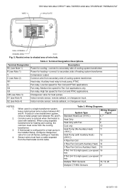
...or heat (B). When using separate transformers for cooling-connect to shaded area of cooling system transformer. Table 3. WIRE TB7100A1000 MULTIPRO™ MULTISPEED AND MULTIPURPOSE THERMOSTAT WALLPLATE WALL OPENING SHADED AREA M22266 Fig. 5. Y Compressor output. Restrict wires to secondary side of heating system transformer... 19, 20 Multiple C7189U Sensors 21 3 62-0273-05 Common wire is optional when thermostat is configured for heating-connect to heat pump, PTAC. If thermostat is used on a two-transformer system, remove metal jumper wire between RC and R. ...
...or heat (B). When using separate transformers for cooling-connect to shaded area of cooling system transformer. Table 3. WIRE TB7100A1000 MULTIPRO™ MULTISPEED AND MULTIPURPOSE THERMOSTAT WALLPLATE WALL OPENING SHADED AREA M22266 Fig. 5. Y Compressor output. Restrict wires to secondary side of heating system transformer... 19, 20 Multiple C7189U Sensors 21 3 62-0273-05 Common wire is optional when thermostat is configured for heating-connect to heat pump, PTAC. If thermostat is used on a two-transformer system, remove metal jumper wire between RC and R. ...
Installation Instructions
Page 4
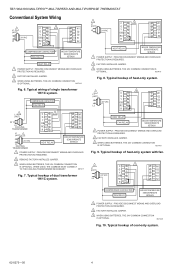
TB7100A1000 MULTIPRO™ MULTISPEED AND MULTIPURPOSE THERMOSTAT Conventional System Wiring L1 1 (HOT) C 3 W1 G G2 Y G3 24 VAC O/B S1 L2 RC S2 R2 COMPRESSOR CONTACTOR FAN RELAY INDOOR TEMPERATURE SENSOR/REMOTE SETBACK HEAT ...
TB7100A1000 MULTIPRO™ MULTISPEED AND MULTIPURPOSE THERMOSTAT Conventional System Wiring L1 1 (HOT) C 3 W1 G G2 Y G3 24 VAC O/B S1 L2 RC S2 R2 COMPRESSOR CONTACTOR FAN RELAY INDOOR TEMPERATURE SENSOR/REMOTE SETBACK HEAT ...
Installation Instructions
Page 5
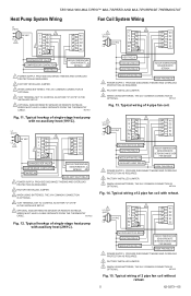
...EITHER "O" OR "B" IN THE INSTALLER SETUP. 5 OPTIONAL INDOOR REMOTE SENSOR OR REMOTE SETBACK. WIRES MUST HAVE A CABLE SEPARATE FROM THE THERMOSTAT CABLE. PROVIDE DISCONNECT MEANS AND OVERLOAD PROTECTION AS REQUIRED. 2 FACTORY INSTALLED JUMPER. 3 WHEN USING BATTERIES, THE 24V COMMON CONNECTION IS ...HEAT RELAY COOLING RELAY LOW FAN RELAY INDOOR TEMPERATURE SENSOR/REMOTE SETBACK MEDIUM FAN RELAY HIGH FAN RELAY 1 POWER SUPPLY. TB7100A1000 MULTIPRO™ MULTISPEED AND MULTIPURPOSE THERMOSTAT Heat Pump System Wiring Fan Coil System Wiring L1 (HOT) 3 24 VAC C W1 L2 G G2 1 Y G3...
...EITHER "O" OR "B" IN THE INSTALLER SETUP. 5 OPTIONAL INDOOR REMOTE SENSOR OR REMOTE SETBACK. WIRES MUST HAVE A CABLE SEPARATE FROM THE THERMOSTAT CABLE. PROVIDE DISCONNECT MEANS AND OVERLOAD PROTECTION AS REQUIRED. 2 FACTORY INSTALLED JUMPER. 3 WHEN USING BATTERIES, THE 24V COMMON CONNECTION IS ...HEAT RELAY COOLING RELAY LOW FAN RELAY INDOOR TEMPERATURE SENSOR/REMOTE SETBACK MEDIUM FAN RELAY HIGH FAN RELAY 1 POWER SUPPLY. TB7100A1000 MULTIPRO™ MULTISPEED AND MULTIPURPOSE THERMOSTAT Heat Pump System Wiring Fan Coil System Wiring L1 (HOT) 3 24 VAC C W1 L2 G G2 1 Y G3...
Installation Instructions
Page 6
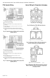
TB7100A1000 MULTIPRO™ MULTISPEED AND MULTIPURPOSE THERMOSTAT PTAC System Wiring Sensor Wiring for Temperature Averaging L1 (HOT) 3 24 VAC C W1 L2 G G2 1 Y G3 4 O/B S1 RC S2 R2 CHANGEOVER VALVE COMPRESSOR CONTACTOR LOW FAN RELAY INDOOR TEMPERATURE SENSOR/REMOTE SETBACK 5 HIGH FAN RELAY 1 POWER SUPPLY. WIRES MUST HAVE A CABLE SEPARATE FROM THE THERMOSTAT...network. Wiring four TR21 (20K ohm) Sensors. WIRES MUST HAVE A CABLE SEPARATE FROM THE THERMOSTAT CABLE. PROVIDE DISCONNECT MEANS AND OVERLOAD PROTECTION AS REQUIRED. 2 FACTORY INSTALLED JUMPER. 3 WHEN ...
TB7100A1000 MULTIPRO™ MULTISPEED AND MULTIPURPOSE THERMOSTAT PTAC System Wiring Sensor Wiring for Temperature Averaging L1 (HOT) 3 24 VAC C W1 L2 G G2 1 Y G3 4 O/B S1 RC S2 R2 CHANGEOVER VALVE COMPRESSOR CONTACTOR LOW FAN RELAY INDOOR TEMPERATURE SENSOR/REMOTE SETBACK 5 HIGH FAN RELAY 1 POWER SUPPLY. WIRES MUST HAVE A CABLE SEPARATE FROM THE THERMOSTAT...network. Wiring four TR21 (20K ohm) Sensors. WIRES MUST HAVE A CABLE SEPARATE FROM THE THERMOSTAT CABLE. PROVIDE DISCONNECT MEANS AND OVERLOAD PROTECTION AS REQUIRED. 2 FACTORY INSTALLED JUMPER. 3 WHEN ...
Installation Instructions
Page 7
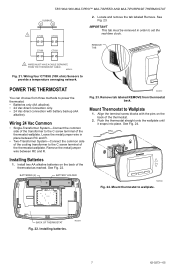
... only. • 24 Vac direct connection with the pins on the back of the thermostat wallplate. See Fig. 23. WALL Installing Batteries 1. M27432 Fig. 21. M22260 Fig. 23. BATTERIES (2) BATTERY HOLDER M23024 Fig. 24. TB7100A1000 MULTIPRO™ MULTISPEED AND MULTIPURPOSE THERMOSTAT SUBBASE S1 S2 1 C7189 C7189 2. Installing batteries. M22259 7 62-0273-05 Remove tab...
... only. • 24 Vac direct connection with the pins on the back of the thermostat wallplate. See Fig. 23. WALL Installing Batteries 1. M27432 Fig. 21. M22260 Fig. 23. BATTERIES (2) BATTERY HOLDER M23024 Fig. 24. TB7100A1000 MULTIPRO™ MULTISPEED AND MULTIPURPOSE THERMOSTAT SUBBASE S1 S2 1 C7189 C7189 2. Installing batteries. M22259 7 62-0273-05 Remove tab...
Installation Instructions
Page 8
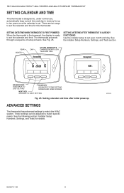
... once the calendar is set. See the following section (Installer Setup Numbers, Settings, and Tests) for details. TB7100A1000 MULTIPRO™ MULTISPEED AND MULTIPURPOSE THERMOSTAT SETTING CALENDAR AND TIME This thermostat is designed to, under normal use, automatically keep current time and day in memory for up to match the... HVAC system. The thermostat proceeds through a sequence of setup screens. See Fig. 25. See the Installer Setup Numbers, Settings, and Tests section. M23023A 62-0273...
... once the calendar is set. See the following section (Installer Setup Numbers, Settings, and Tests) for details. TB7100A1000 MULTIPRO™ MULTISPEED AND MULTIPURPOSE THERMOSTAT SETTING CALENDAR AND TIME This thermostat is designed to, under normal use, automatically keep current time and day in memory for up to match the... HVAC system. The thermostat proceeds through a sequence of setup screens. See Fig. 25. See the Installer Setup Numbers, Settings, and Tests section. M23023A 62-0273...
Installation Instructions
Page 9
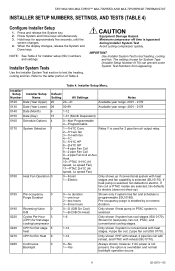
..., fan defaults to electric. however, if AC power is not present, the option is bypassed during Installer System Test Avoid cycling compressor quickly. TB7100A1000 MULTIPRO™ MULTISPEED AND MULTIPURPOSE THERMOSTAT INSTALLER SETUP NUMBERS, SETTINGS, AND TESTS (TABLE 4) Configure Installer Setup 1. Press and release the System key. 2. Press System and Done keys simultaneously. 3. NOTE...
..., fan defaults to electric. however, if AC power is not present, the option is bypassed during Installer System Test Avoid cycling compressor quickly. TB7100A1000 MULTIPRO™ MULTISPEED AND MULTIPURPOSE THERMOSTAT INSTALLER SETUP NUMBERS, SETTINGS, AND TESTS (TABLE 4) Configure Installer Setup 1. Press and release the System key. 2. Press System and Done keys simultaneously. 3. NOTE...
Installation Instructions
Page 10
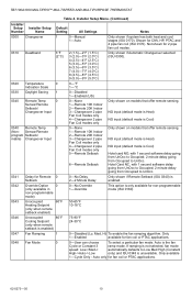
... delay going from UnOcc to Occupied; 2 minute delay going from Occupied to UnOcc. Auto only for CNV, HP, PTAC and 4 pipe fan coil (ISU 0170). TB7100A1000 MULTIPRO™ MULTISPEED AND MULTIPURPOSE THERMOSTAT Table 4.
... delay going from UnOcc to Occupied; 2 minute delay going from Occupied to UnOcc. Auto only for CNV, HP, PTAC and 4 pipe fan coil (ISU 0170). TB7100A1000 MULTIPRO™ MULTISPEED AND MULTIPURPOSE THERMOSTAT Table 4.
Installation Instructions
Page 11
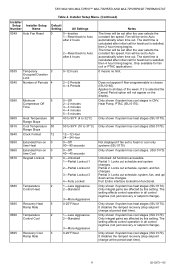
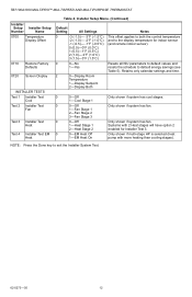
... Stops Clock Format 12 Extended Fan-on 0 time Heat Extended Fan-on the display. Only shown if system has cool stages (ISU 0170). TB7100A1000 MULTIPRO™ MULTISPEED AND MULTIPURPOSE THERMOSTAT Table 4. Applies to Auto automatically when time out. Only shown if system has cool stages in all control regimes (not just recovery or...
... Stops Clock Format 12 Extended Fan-on 0 time Heat Extended Fan-on the display. Only shown if system has cool stages (ISU 0170). TB7100A1000 MULTIPRO™ MULTISPEED AND MULTIPURPOSE THERMOSTAT Table 4. Applies to Auto automatically when time out. Only shown if system has cool stages in all control regimes (not just recovery or...
Installation Instructions
Page 12
... Both Notes This offset applies to both the control temperature and to default energy savings (see Table 5). Only shown if system has fan. TB7100A1000 MULTIPRO™ MULTISPEED AND MULTIPURPOSE THERMOSTAT Installer Setup Number Installer Setup Name 0700 Temperature Display Offset 0710 0720 Restore Factory Defaults Screen Display INSTALLER TESTS Test 1 Installer Test Cool...
... Both Notes This offset applies to both the control temperature and to default energy savings (see Table 5). Only shown if system has fan. TB7100A1000 MULTIPRO™ MULTISPEED AND MULTIPURPOSE THERMOSTAT Installer Setup Number Installer Setup Name 0700 Temperature Display Offset 0710 0720 Restore Factory Defaults Screen Display INSTALLER TESTS Test 1 Installer Test Cool...
Installation Instructions
Page 13
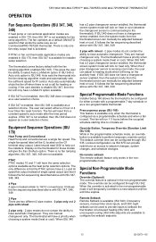
...schedule starting time to disable ISU 347, then the fan will only have the same selection options available as our CommercialPRO TB7220 thermostat. Override Button, Temporary Override (Duration Limit ISU 535) While in the programmable schedule mode, an override button is available as... and 2 pipe with reheat - 2 pipe modes do not contain the ability to be configured for heating or cooling. OPERATION TB7100A1000 MULTIPRO™ MULTISPEED AND MULTIPURPOSE THERMOSTAT Fan Sequence Operations (ISU 347, 348, 349) If heat pump or conventional application modes are enabled in ISU 170, then ...
...schedule starting time to disable ISU 347, then the fan will only have the same selection options available as our CommercialPRO TB7220 thermostat. Override Button, Temporary Override (Duration Limit ISU 535) While in the programmable schedule mode, an override button is available as... and 2 pipe with reheat - 2 pipe modes do not contain the ability to be configured for heating or cooling. OPERATION TB7100A1000 MULTIPRO™ MULTISPEED AND MULTIPURPOSE THERMOSTAT Fan Sequence Operations (ISU 347, 348, 349) If heat pump or conventional application modes are enabled in ISU 170, then ...
Installation Instructions
Page 14
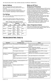
...equipment in the Installer Setup. Loose or broken wire connection between power and common. If 24 Vac is present, the thermostat is incorrect. The Minimum-Off Timer is chosen. TROUBLESHOOTING (TABLE 6) Table 6. Troubleshooting. on indoor temperature. Check Installer...equipment to find the cause of the problem. Heating or cooling does Thermostat minimum off : - If voltage is chosen. TB7100A1000 MULTIPRO™ MULTISPEED AND MULTIPURPOSE THERMOSTAT System Settings Heat-Thermostat controls the heating system. Fan is not present, check wire connection...
...equipment in the Installer Setup. Loose or broken wire connection between power and common. If 24 Vac is present, the thermostat is incorrect. The Minimum-Off Timer is chosen. TROUBLESHOOTING (TABLE 6) Table 6. Troubleshooting. on indoor temperature. Check Installer...equipment to find the cause of the problem. Heating or cooling does Thermostat minimum off : - If voltage is chosen. TB7100A1000 MULTIPRO™ MULTISPEED AND MULTIPURPOSE THERMOSTAT System Settings Heat-Thermostat controls the heating system. Fan is not present, check wire connection...
Installation Instructions
Page 15
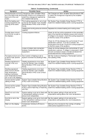
... is not in the display. System setting is set to Heat and/ Set the system setting to Cool Only. TB7100A1000 MULTIPRO™ MULTISPEED AND MULTIPURPOSE THERMOSTAT Table 6. Both the heating and cooling equipment are shorted Separate the shorted heating and cooling wires. Check the cooling... Cool On is set to match the installed heating and/or cooling equipment. Wait up to five minutes for 24 Vac between thermostat and cooling equipment. Cooling equipment failure. Fan (Setting 0180). Cannot set the system System Type (Installer Setup Number Set System ...
... is not in the display. System setting is set to Heat and/ Set the system setting to Cool Only. TB7100A1000 MULTIPRO™ MULTISPEED AND MULTIPURPOSE THERMOSTAT Table 6. Both the heating and cooling equipment are shorted Separate the shorted heating and cooling wires. Check the cooling... Cool On is set to match the installed heating and/or cooling equipment. Wait up to five minutes for 24 Vac between thermostat and cooling equipment. Cooling equipment failure. Fan (Setting 0180). Cannot set the system System Type (Installer Setup Number Set System ...
Installation Instructions
Page 16
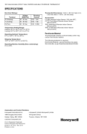
... customer.honeywell.com ® U.S. Thermostat Dimensions: 3-3/4 in. (95 mm) high x 6 in. (152 mm) wide x 1-3/8 in U.S.A. TR21-A Wall-Mount Remote Indoor Sensor: 10K ohm NTC. Cooling: 50°F to 99°F (10°C to 65.6°C). Shipping Temperature: -30°F to 150°F (-34.4°C to 37°C). TB7100A1000 MULTIPRO™ MULTISPEED AND MULTIPURPOSE THERMOSTAT SPECIFICATIONS...
... customer.honeywell.com ® U.S. Thermostat Dimensions: 3-3/4 in. (95 mm) high x 6 in. (152 mm) wide x 1-3/8 in U.S.A. TR21-A Wall-Mount Remote Indoor Sensor: 10K ohm NTC. Cooling: 50°F to 99°F (10°C to 65.6°C). Shipping Temperature: -30°F to 150°F (-34.4°C to 37°C). TB7100A1000 MULTIPRO™ MULTISPEED AND MULTIPURPOSE THERMOSTAT SPECIFICATIONS...


