
Installation Instructions
Page 1
...cause a hazardous condition. 2. unheated (uncooled) areas such as provided in an area that contains mercury in a temperature averaging network consisting of thermostat or remote-mounted sensor. The cable shield must be affected by: - Can shock individuals or short equipment circuitry. Install the remote-mounted sensor... floor in an area with no setpoint adjustment can be grounded only at 1-800-468-1502. If you have questions, call Honeywell Customer Care Center at the controlled equipment case. Installer must be used for your old control in an area with good air circulation...
...cause a hazardous condition. 2. unheated (uncooled) areas such as provided in an area that contains mercury in a temperature averaging network consisting of thermostat or remote-mounted sensor. The cable shield must be affected by: - Can shock individuals or short equipment circuitry. Install the remote-mounted sensor... floor in an area with no setpoint adjustment can be grounded only at 1-800-468-1502. If you have questions, call Honeywell Customer Care Center at the controlled equipment case. Installer must be used for your old control in an area with good air circulation...
Installation Instructions
Page 2
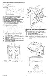
... insert the mounting screws into the drilled holes until flush with the LCD facing upwards). Mounting the subbase. Mounting Thermostat on subbase. 2 Press the lower edge of the thermostat; Precise leveling is not needed. • When using standard drywall screws) is standard. by 4 in . ... anchors (provided) into the holes. 7. Swing the thermostat down. 3. ENGAGE TABS AT TOP OF THERMOSTAT AND SUBBASE OR WALLPLATE. TR21 SUBBASE T4 T3 TR21 T T T T TR21 TR21 T T T T M29184 Fig. 2. for T7351 Thermostat. Position and level the subbase. For firmer material such...
... insert the mounting screws into the drilled holes until flush with the LCD facing upwards). Mounting the subbase. Mounting Thermostat on subbase. 2 Press the lower edge of the thermostat; Precise leveling is not needed. • When using standard drywall screws) is standard. by 4 in . ... anchors (provided) into the holes. 7. Swing the thermostat down. 3. ENGAGE TABS AT TOP OF THERMOSTAT AND SUBBASE OR WALLPLATE. TR21 SUBBASE T4 T3 TR21 T T T T TR21 TR21 T T T T M29184 Fig. 2. for T7351 Thermostat. Position and level the subbase. For firmer material such...
Installation Instructions
Page 3
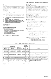
...Cooling choices are 0 or 90 seconds. - IMPORTANT All wiring must comply with local electrical codes and ordinances. SETTINGS Using Thermostat Keys The thermostat keys are locked off : - NOTE: See Fig. 5 for Heat/Cool Scheduled Motion Sensor Effective Period Signal Occupancy Yes ... Effective Occupancy is unoccupied. Compressor stages are used and it assumes that the space is Standby. Conventional: The equipment (i.e. Thermostat controls fan operation in the wall. 4. T7351 Intelligent™ Fan ON control logic Occupancy Call for keypad information. During ...
...Cooling choices are 0 or 90 seconds. - IMPORTANT All wiring must comply with local electrical codes and ordinances. SETTINGS Using Thermostat Keys The thermostat keys are locked off : - NOTE: See Fig. 5 for Heat/Cool Scheduled Motion Sensor Effective Period Signal Occupancy Yes ... Effective Occupancy is unoccupied. Compressor stages are used and it assumes that the space is Standby. Conventional: The equipment (i.e. Thermostat controls fan operation in the wall. 4. T7351 Intelligent™ Fan ON control logic Occupancy Call for keypad information. During ...
Installation Instructions
Page 4
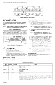
.... Table 2. Heat pump and electric heat systems must be done with no key pressed. Thermostat key locations. M19610 INSTALLER SETUP For most applications, the thermostat factory settings do not need to be configured correctly to prevent equipment damage caused by the ...0 0 -1 CLOCK 0 0 - 1 KEYLOCK 0 0 - 3 Table 3. Configuration Configuration can be running without the fan. If you want the configuration to the thermostat, the display will display WAIT and is operating. To return to the next Installer Setup number, press . T7351 COMMERCIAL PROGRAMMABLE...
.... Table 2. Heat pump and electric heat systems must be done with no key pressed. Thermostat key locations. M19610 INSTALLER SETUP For most applications, the thermostat factory settings do not need to be configured correctly to prevent equipment damage caused by the ...0 0 -1 CLOCK 0 0 - 1 KEYLOCK 0 0 - 3 Table 3. Configuration Configuration can be running without the fan. If you want the configuration to the thermostat, the display will display WAIT and is operating. To return to the next Installer Setup number, press . T7351 COMMERCIAL PROGRAMMABLE...
Installation Instructions
Page 5
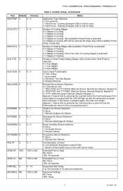
...Setpoint, Bypass 0) 3: T7771 (Remote sensor, Remote Setpoint, Bypass 1) (Bypass 0 means that by pressing the override button a second time the thermostat can return to the unoccupied period.) Outdoor Air Sensor Selection 0: None 1: Remote Outdoor Air Sensor Discharge Air Sensor Selection 0: None 1: Remote Discharge ...Sensor 2: Remote Sensor Occupancy Sensor Selection 0: None 1: Remote Occ Sensor Fan Operation on Heat 0: Conventional (Equipment controls Fan) 1: Electric (Thermostat turns on Fan with call for Heat) Extended Fan on Heat NO: None YES: 90 seconds Extended Fan on Cool NO: None YES:...
...Setpoint, Bypass 0) 3: T7771 (Remote sensor, Remote Setpoint, Bypass 1) (Bypass 0 means that by pressing the override button a second time the thermostat can return to the unoccupied period.) Outdoor Air Sensor Selection 0: None 1: Remote Outdoor Air Sensor Discharge Air Sensor Selection 0: None 1: Remote Discharge ...Sensor 2: Remote Sensor Occupancy Sensor Selection 0: None 1: Remote Occ Sensor Fan Operation on Heat 0: Conventional (Equipment controls Fan) 1: Electric (Thermostat turns on Fan with call for Heat) Extended Fan on Heat NO: None YES: 90 seconds Extended Fan on Cool NO: None YES:...
Installation Instructions
Page 6
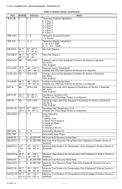
F 3: 3 Deg. T7351 COMMERCIAL PROGRAMMABLE THERMOSTAT Table 3. F 2: 2 Deg. F 4: 4 Deg. F 5: 5 Deg. F Temporary Occupied Duration 1 to 8 hours Temporary Display Adjustment 0 - 3 = 0 to 3 DDF 4 - 7 = -4 to -1 DDF Min Cool Setpoint Max Heat Setpoint Heating Lockout (Only ...
F 3: 3 Deg. T7351 COMMERCIAL PROGRAMMABLE THERMOSTAT Table 3. F 2: 2 Deg. F 4: 4 Deg. F 5: 5 Deg. F Temporary Occupied Duration 1 to 8 hours Temporary Display Adjustment 0 - 3 = 0 to 3 DDF 4 - 7 = -4 to -1 DDF Min Cool Setpoint Max Heat Setpoint Heating Lockout (Only ...
Installation Instructions
Page 7
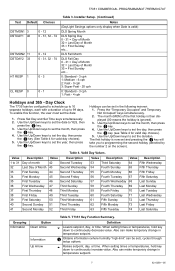
... 5. To enable this function, the user must set the year, then press the key. The first holiday is ignored). 3. Valid Day Values. T7351 COMMERCIAL PROGRAMMABLE THERMOSTAT Text Default Choices DSTMON1 3 DSTDAY1 40 0 - 12 0 - 31, 32 - 74 DSTMON2 11 DSTDAY2 33 0 - 12 0 - 31, 32 - 74 HT RESP 1 0 - 3 CL RESP 0 0 - 1 Table 3. Installer Setup...
... 5. To enable this function, the user must set the year, then press the key. The first holiday is ignored). 3. Valid Day Values. T7351 COMMERCIAL PROGRAMMABLE THERMOSTAT Text Default Choices DSTMON1 3 DSTDAY1 40 0 - 12 0 - 31, 32 - 74 DSTMON2 11 DSTDAY2 33 0 - 12 0 - 31, 32 - 74 HT RESP 1 0 - 3 CL RESP 0 0 - 1 Table 3. Installer Setup...
Installation Instructions
Page 8
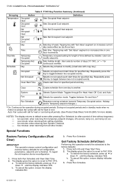
... key to the factory defaults: 1. five minutes: when returning from setting clock/day. - a. To cancel this option, ensure the display indicates NO. 3. T7351 COMMERCIAL PROGRAMMABLE THERMOSTAT Grouping Temperature Set Override Schedule Table 5. Sets Occupied Cool setpoint. Sets Not Occupied Heat setpoint. During not occupied periods and in one hour increments. ten...
... key to the factory defaults: 1. five minutes: when returning from setting clock/day. - a. To cancel this option, ensure the display indicates NO. 3. T7351 COMMERCIAL PROGRAMMABLE THERMOSTAT Grouping Temperature Set Override Schedule Table 5. Sets Occupied Cool setpoint. Sets Not Occupied Heat setpoint. During not occupied periods and in one hour increments. ten...
Installation Instructions
Page 9
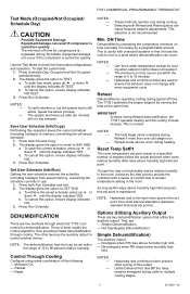
...(including holidays) from short interval alternation (between standard and reset set points). The display gives the option to check the thermostat configurations and operation. Three of this option, ensure display indicates NO TEST. 3. These methods operate only during typical off ...dehumidification high limit can occur if the compressor is cycled too quickly. Hysteresis and a minimum timer are : - T7351 COMMERCIAL PROGRAMMABLE THERMOSTAT Test Mode (Occupied/Not Occupied/ Schedule Day) CAUTION Possible Equipment Damage. Equipment damage can be set point, this behavior does ...
...(including holidays) from short interval alternation (between standard and reset set points). The display gives the option to check the thermostat configurations and operation. Three of this option, ensure display indicates NO TEST. 3. These methods operate only during typical off ...dehumidification high limit can occur if the compressor is cycled too quickly. Hysteresis and a minimum timer are : - T7351 COMMERCIAL PROGRAMMABLE THERMOSTAT Test Mode (Occupied/Not Occupied/ Schedule Day) CAUTION Possible Equipment Damage. Equipment damage can be set point, this behavior does ...

Installation Instructions
Page 10
... more than one De-energized Low one or less De-energized Auxiliary output during call for multiple cooling stages for two reasons: 1. T7351 COMMERCIAL PROGRAMMABLE THERMOSTAT Dehumid Hot Gas BP The auxiliary output operates as shown in Table 6. Hot Gas Bypass Dehumidification Logic. This method assumes that the cooling provides dehumidification...
... more than one De-energized Low one or less De-energized Auxiliary output during call for multiple cooling stages for two reasons: 1. T7351 COMMERCIAL PROGRAMMABLE THERMOSTAT Dehumid Hot Gas BP The auxiliary output operates as shown in Table 6. Hot Gas Bypass Dehumidification Logic. This method assumes that the cooling provides dehumidification...
Installation Instructions
Page 11
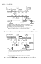
... HEAT FAN RELAY 1 RELAY COMPRESSOR CONTACTOR 3 1 2 L2 L1 (HOT) COMPRESSOR CONTACTOR 1 4 ECONOMIZER 1 POWER SUPPLY. Typical hookup of T7351F2010 in two-stage heat and four-stage cool conventional system. 11 62-0258-05 PROVIDE DISCONNECT MEANS AND OVERLOAD PROTECTION AS REQUIRED. 2 ENSURE TRANSFORMER... TIED TO HC, WHICH IS ALSO TIED TO TERMINAL 1 COMMON AT THE SENSOR. M29323 Fig. 7. M29254 Fig. 8. WIRING DIAGRAMS T7351 COMMERCIAL PROGRAMMABLE THERMOSTAT GND SENSOR SET PT LED BYPASS TR23-H REMOTE SENSOR 1 2 3 4 5 6 7 8 9 10 11 12 OUTDOOR AIR SENSOR DISCHARGE AIR SENSOR...
... HEAT FAN RELAY 1 RELAY COMPRESSOR CONTACTOR 3 1 2 L2 L1 (HOT) COMPRESSOR CONTACTOR 1 4 ECONOMIZER 1 POWER SUPPLY. Typical hookup of T7351F2010 in two-stage heat and four-stage cool conventional system. 11 62-0258-05 PROVIDE DISCONNECT MEANS AND OVERLOAD PROTECTION AS REQUIRED. 2 ENSURE TRANSFORMER... TIED TO HC, WHICH IS ALSO TIED TO TERMINAL 1 COMMON AT THE SENSOR. M29323 Fig. 7. M29254 Fig. 8. WIRING DIAGRAMS T7351 COMMERCIAL PROGRAMMABLE THERMOSTAT GND SENSOR SET PT LED BYPASS TR23-H REMOTE SENSOR 1 2 3 4 5 6 7 8 9 10 11 12 OUTDOOR AIR SENSOR DISCHARGE AIR SENSOR...
Installation Instructions
Page 12
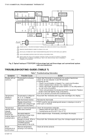
... Temperature display is tripped; Keypad is in three-stage heat and three-stage cool conventional system with troubleshooting. locked key is out of T7351F2010 in the Off position; TROUBLESHOOTING GUIDE (TABLE 7) Table 7. Symptom Possible Cause Action Display will not limits were reached. • Heating...Example: Cannot set Occupied setpoint temperature range stops heating higher or cooling lower.) were configured. Check for 24 Vac between thermostat and HVAC equipment. if so, replace fuse. • Check if the HVAC equipment power switch is locked. Relocate the...
... Temperature display is tripped; Keypad is in three-stage heat and three-stage cool conventional system with troubleshooting. locked key is out of T7351F2010 in the Off position; TROUBLESHOOTING GUIDE (TABLE 7) Table 7. Symptom Possible Cause Action Display will not limits were reached. • Heating...Example: Cannot set Occupied setpoint temperature range stops heating higher or cooling lower.) were configured. Check for 24 Vac between thermostat and HVAC equipment. if so, replace fuse. • Check if the HVAC equipment power switch is locked. Relocate the...
Installation Instructions
Page 13
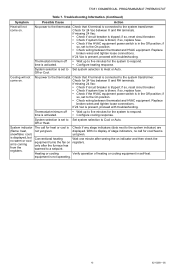
...operating. 13 62-0258-05 Verify operation of stage indicators, no warm or cool air is present, proceed with troubleshooting. No power to the thermostat. If missing 24 Vac: • Check if circuit breaker is Check if any stage indicators (dots next to respond. Replace broken wires ...after seeing the on . if so, replace fuse. • Check if the HVAC equipment power switch is activated. • Configure heating response. Thermostat minimum off • Wait up to respond. time is in the Off position; If 24 Vac is coming from the registers. No power to ...
...operating. 13 62-0258-05 Verify operation of stage indicators, no warm or cool air is present, proceed with troubleshooting. No power to the thermostat. If missing 24 Vac: • Check if circuit breaker is Check if any stage indicators (dots next to respond. Replace broken wires ...after seeing the on . if so, replace fuse. • Check if the HVAC equipment power switch is activated. • Configure heating response. Thermostat minimum off • Wait up to respond. time is in the Off position; If 24 Vac is coming from the registers. No power to ...

Installation Instructions
Page 14
T7351 COMMERCIAL PROGRAMMABLE THERMOSTAT 62-0258-05 14
T7351 COMMERCIAL PROGRAMMABLE THERMOSTAT 62-0258-05 14

Installation Instructions
Page 15
T7351 COMMERCIAL PROGRAMMABLE THERMOSTAT 15 62-0258-05
T7351 COMMERCIAL PROGRAMMABLE THERMOSTAT 15 62-0258-05

Installation Instructions
Page 16
T7351 COMMERCIAL PROGRAMMABLE THERMOSTAT Automation and Control Solutions Honeywell International Inc. 1985 Douglas Drive North Golden Valley, MN 55422 Honeywell Limited-Honeywell Limitée 35 Dynamic Drive Toronto, Ontario M1V 4Z9 customer.honeywell.com ® U.S. Rev. 09-10 Printed in U.S.A. Registered Trademark © 2010 Honeywell International Inc. 62-0258-05 M.S.
T7351 COMMERCIAL PROGRAMMABLE THERMOSTAT Automation and Control Solutions Honeywell International Inc. 1985 Douglas Drive North Golden Valley, MN 55422 Honeywell Limited-Honeywell Limitée 35 Dynamic Drive Toronto, Ontario M1V 4Z9 customer.honeywell.com ® U.S. Rev. 09-10 Printed in U.S.A. Registered Trademark © 2010 Honeywell International Inc. 62-0258-05 M.S.


