
Owner's Manual
Page 2
... control and reliable operation for instructions regarding recycling and the proper disposal of its useful life. This allows you have questions, call Honeywell Inc. If this thermostat will automatically lower and raise the temperature in a sealed tube. at the end of this manual to learn how to use your fuel costs, while awakening (or returning home) to a comfortable temperature. The Honeywell name is replacing a control...
... control and reliable operation for instructions regarding recycling and the proper disposal of its useful life. This allows you have questions, call Honeywell Inc. If this thermostat will automatically lower and raise the temperature in a sealed tube. at the end of this manual to learn how to use your fuel costs, while awakening (or returning home) to a comfortable temperature. The Honeywell name is replacing a control...
Owner's Manual
Page 3
Table Of Contents PAGE Features Of Your Thermostat ...4 Setting The Temperature ...7 Setting Subbase Switches ...8 Inserting Timer Backup Batteries ...9 Setting The Timer ...10 Programming ...11 Troubleshooting ...14 Servicing The Thermostat ...21 Warranty ...23 3 69-0563-2
Table Of Contents PAGE Features Of Your Thermostat ...4 Setting The Temperature ...7 Setting Subbase Switches ...8 Inserting Timer Backup Batteries ...9 Setting The Timer ...10 Programming ...11 Troubleshooting ...14 Servicing The Thermostat ...21 Warranty ...23 3 69-0563-2
Owner's Manual
Page 4
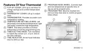
... COVER. Controls high and low temperature at specific time of day as set timer for 24-hour dial. 8 PROGRAM INDEX WHEEL. Must be inserted into 24-hour timer dial slots to adjust timer. 3 THERMOMETER. Lift up to hold the programming pins. 6 TIMER SETTING KNOB. Turn clockwise to the time indicator. 7 TIME INDICATOR. time to match the correct a.m. Left (blue mark) controls the low temperature, right (red mark) controls the high temperature. 5 TIMER. or p.m. Arrow head indicates time for energy savings and comfort temperature periods. 2 THERMOSTAT COVER...
... COVER. Controls high and low temperature at specific time of day as set timer for 24-hour dial. 8 PROGRAM INDEX WHEEL. Must be inserted into 24-hour timer dial slots to adjust timer. 3 THERMOMETER. Lift up to hold the programming pins. 6 TIMER SETTING KNOB. Turn clockwise to the time indicator. 7 TIME INDICATOR. time to match the correct a.m. Left (blue mark) controls the low temperature, right (red mark) controls the high temperature. 5 TIMER. or p.m. Arrow head indicates time for energy savings and comfort temperature periods. 2 THERMOSTAT COVER...
Owner's Manual
Page 5
Provides mounting base and wiring connections for program pin insertion. 11 MERCURY BULB AND BIMETAL ELEMENT (2). 5 6 9 11 12 M8744 10 8 7 M8745 10 PIN SLOTS. Provide automatic temperature control by switching the heating or cooling system on 24-hour dial at 10-minute intervals for heating or cooling thermostat without system or fan switching. 5 69-0563-2 Located on and off. 12 WALLPLATE.
Provides mounting base and wiring connections for program pin insertion. 11 MERCURY BULB AND BIMETAL ELEMENT (2). 5 6 9 11 12 M8744 10 8 7 M8745 10 PIN SLOTS. Provide automatic temperature control by switching the heating or cooling system on 24-hour dial at 10-minute intervals for heating or cooling thermostat without system or fan switching. 5 69-0563-2 Located on and off. 12 WALLPLATE.
Owner's Manual
Page 6
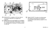
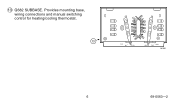
Provides mounting base, wiring connections and manual switching control for heating/cooling thermostat. 13 R G FAN ON AUTO O B W Y HEAT COOL OFF M1551 6 69-0563-2 13 Q682 SUBBASE.
Provides mounting base, wiring connections and manual switching control for heating/cooling thermostat. 13 R G FAN ON AUTO O B W Y HEAT COOL OFF M1551 6 69-0563-2 13 Q682 SUBBASE.

Owner's Manual
Page 7
For Cooling Set the left lever (blue mark) to the energy savings temperature you want when you are sleeping or your home is unoccupied. NOTE: You may override the time program by setting both the red and blue levers to the temperature you want when you want for normal comfort periods. Setting The Temperature For Heating Set the left lever (blue mark) to the temperature you want for...
For Cooling Set the left lever (blue mark) to the energy savings temperature you want when you are sleeping or your home is unoccupied. NOTE: You may override the time program by setting both the red and blue levers to the temperature you want when you want for normal comfort periods. Setting The Temperature For Heating Set the left lever (blue mark) to the temperature you want for...
Owner's Manual
Page 8
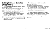
... thermostat in the detent over desired function indicator mark for proper circuit operation. 8 69-0563-2 OFF- To switch positions, use thumb or index finger to slide lever to desired position. Both the heating and cooling systems are Off. In a heating only application, only heating operates. If the fan switch is at the AUTO position, the fan is Off. Setting Subbase Switches (if applicable) The subbase system switch controls system operation...
... thermostat in the detent over desired function indicator mark for proper circuit operation. 8 69-0563-2 OFF- To switch positions, use thumb or index finger to slide lever to desired position. Both the heating and cooling systems are Off. In a heating only application, only heating operates. If the fan switch is at the AUTO position, the fan is Off. Setting Subbase Switches (if applicable) The subbase system switch controls system operation...
Owner's Manual
Page 9
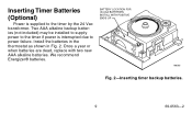
BATTERY LOCATION FOR (2) AAA BATTERIES; Install the batteries in the thermostat as shown in Fig. 2. INSTALL WITH POSITIVE ENDS UP M8585 Fig. 2-Inserting timer backup batteries. 9 69-0563-2 Once a year or when batteries are dead, replace with two new AAA alkaline batteries. Two AAA alkaline backup batteries (not included) may be installed to supply power to the timer if power is supplied to power failure. We recommend Energizer® batteries. Inserting Timer Batteries (Optional) Power is interrupted due to the timer by the 24 Vac transformer.
BATTERY LOCATION FOR (2) AAA BATTERIES; Install the batteries in the thermostat as shown in Fig. 2. INSTALL WITH POSITIVE ENDS UP M8585 Fig. 2-Inserting timer backup batteries. 9 69-0563-2 Once a year or when batteries are dead, replace with two new AAA alkaline batteries. Two AAA alkaline backup batteries (not included) may be installed to supply power to the timer if power is supplied to power failure. We recommend Energizer® batteries. Inserting Timer Batteries (Optional) Power is interrupted due to the timer by the 24 Vac transformer.
Owner's Manual
Page 10
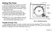
... Timer Lift thermostat flip-up cover and you will point directly to the current time by carefully turning the knob clockwise Do not reverse the knob. When time is correctly set, the Time Indicator Arrow (See Fig. 3) will point to light band on dial. For 11 a.m., the arrow will point to the timer mechanism may occur. 10 69-0563-2 PROGRAM DIAL PROGRAM PIN (6) TIMER SETTING KNOB TIME INDICATOR...
... Timer Lift thermostat flip-up cover and you will point directly to the current time by carefully turning the knob clockwise Do not reverse the knob. When time is correctly set, the Time Indicator Arrow (See Fig. 3) will point to light band on dial. For 11 a.m., the arrow will point to the timer mechanism may occur. 10 69-0563-2 PROGRAM DIAL PROGRAM PIN (6) TIMER SETTING KNOB TIME INDICATOR...
Owner's Manual
Page 11
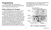
... for each energy savings period. 24-HOUR PROGRAM DIAL (GRAY AREA FOR NIGHT SETTINGS) FLIP-UP COVER PROGRAM PINS THERMOSTAT COVER PROGRAM PIN SLOT PROGRAM INDEX WHEEL TIME INDICATOR ARROW PROGRAM PIN STORAGE M7348 Fig. 4-Program components. 11 69-0563-2 The red pins start the low-temperature period. We recommend at ten-minute intervals. for low temperature (energy saving period). You can program your thermostat to six temperature changes with your thermostat. A heating program has been...
... for each energy savings period. 24-HOUR PROGRAM DIAL (GRAY AREA FOR NIGHT SETTINGS) FLIP-UP COVER PROGRAM PINS THERMOSTAT COVER PROGRAM PIN SLOT PROGRAM INDEX WHEEL TIME INDICATOR ARROW PROGRAM PIN STORAGE M7348 Fig. 4-Program components. 11 69-0563-2 The red pins start the low-temperature period. We recommend at ten-minute intervals. for low temperature (energy saving period). You can program your thermostat to six temperature changes with your thermostat. A heating program has been...

Owner's Manual
Page 12
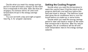
... with the program index wheel. • On heating-cooling systems, you wake up or arrive home. The half-hour head start gives the furnace time to set new times for your colors and time for reprogramming at the next heating season. Do not attempt to reach the comfort level. M8677 Fig. 5-Program examples. 12 69-0563-2 Write down your cooling program. To change the temperature setting lever...
... with the program index wheel. • On heating-cooling systems, you wake up or arrive home. The half-hour head start gives the furnace time to set new times for your colors and time for reprogramming at the next heating season. Do not attempt to reach the comfort level. M8677 Fig. 5-Program examples. 12 69-0563-2 Write down your cooling program. To change the temperature setting lever...
Owner's Manual
Page 13
... insert a red pin at the notch that corresponds to this time. The half-hour head start gives the air conditioner time to cool the house before this time and insert a blue pin. Decide when you want the energy savings period to start and insert a blue pin at the notch that corresponds to this time. You can set both a day and night program. See...
... insert a red pin at the notch that corresponds to this time. The half-hour head start gives the air conditioner time to cool the house before this time and insert a blue pin. Decide when you want the energy savings period to start and insert a blue pin at the notch that corresponds to this time. You can set both a day and night program. See...
Owner's Manual
Page 14
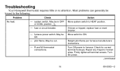
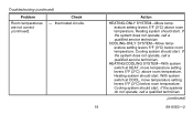
... flame per furnace manufacturers instructions. - Firmly tighten all terminal screws. Most problems can generally be Move switch to HEAT position. fuse or circuit breaker. Check for correct terminal hookups. May be in OFF or COOL position. 1 - Turn Off power to the following: Problem Check Action No heat. - If blown or tripped, replace fuse or reset breaker. - Off. - Repair any frayed or broken wires. system switch. Troubleshooting Your Honeywell thermostat requires...
... flame per furnace manufacturers instructions. - Firmly tighten all terminal screws. Most problems can generally be Move switch to HEAT position. fuse or circuit breaker. Check for correct terminal hookups. May be in OFF or COOL position. 1 - Turn Off power to the following: Problem Check Action No heat. - If blown or tripped, replace fuse or reset breaker. - Off. - Repair any frayed or broken wires. system switch. Troubleshooting Your Honeywell thermostat requires...
Owner's Manual
Page 15
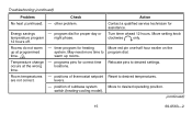
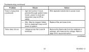
... problem. May need more time to desired settings. Room temperatures - program dial for correct time locations. Move setting knob clockwise only. Relocate pins to warm up at programmed time. 2 Temperature change occurs at the wrong time. - Troubleshooting (continued) Problem Check Action No heat (continued). - Turn timer ahead 12 hours. Move to desired temperatures. are not correct. Move red pin one-half hour earlier on the program dial. positions of subbase system switch (heating-cooling model...
... problem. May need more time to desired settings. Room temperatures - program dial for correct time locations. Move setting knob clockwise only. Relocate pins to warm up at programmed time. 2 Temperature change occurs at the wrong time. - Troubleshooting (continued) Problem Check Action No heat (continued). - Turn timer ahead 12 hours. Move to desired temperatures. are not correct. Move red pin one-half hour earlier on the program dial. positions of subbase system switch (heating-cooling model...
Owner's Manual
Page 16
... room temperature. Heating system should start . thermostat circuits. If the system does not operate, call a qualified service technician. If the system does not operate, call a qualified service technician. Cooling system should start . Troubleshooting (continued) Problem Room temperatures are not correct (continued). HEATING/COOLING SYSTEM-With system switch at COOL, move temperature setting levers 5°F (3°C) above room temperature. With system switch at HEAT, move temperature setting levers 5°F (3°C) below room temperature. Heating system...
... room temperature. Heating system should start . thermostat circuits. If the system does not operate, call a qualified service technician. If the system does not operate, call a qualified service technician. Cooling system should start . Troubleshooting (continued) Problem Room temperatures are not correct (continued). HEATING/COOLING SYSTEM-With system switch at COOL, move temperature setting levers 5°F (3°C) above room temperature. With system switch at HEAT, move temperature setting levers 5°F (3°C) below room temperature. Heating system...
Owner's Manual
Page 17
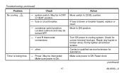
... a qualified service technician for correct terminal hookups. Y and R thermostat connections. - Make sure power is blown or breaker tripped, replace or reset. system switch. condenser switch position. Move to ON position. Repair any frayed or broken wires. Reset clock. (continued) 17 69-0563-2 Power. fuse or circuit breaker. - Make sure power is losing time. - other Timer is Off. May be interrupted. Firmly tighten all terminal screws. Troubleshooting (continued) Problem Check No cooling. 1 -
... a qualified service technician for correct terminal hookups. Y and R thermostat connections. - Make sure power is blown or breaker tripped, replace or reset. system switch. condenser switch position. Move to ON position. Repair any frayed or broken wires. Reset clock. (continued) 17 69-0563-2 Power. fuse or circuit breaker. - Make sure power is losing time. - other Timer is Off. May be interrupted. Firmly tighten all terminal screws. Troubleshooting (continued) Problem Check No cooling. 1 -
Owner's Manual
Page 18
If clock powered through system transformer, power to page 19 for cause and action. (continued) 18 69-0563-2 filter. Refer to clock and equipment may be clogged. Wire separate transformer to system. - Troubleshooting (continued) Problem Timer is losing time (continued). Timer does not run. - high limit control. Replace filter and reset clock. Safety limit on safety. Remove the thermostat from the wallplate or subbase, and measure the voltage. May be Off on equipment may cut off power to power clock. Check Action - voltage across the C and R terminals.
If clock powered through system transformer, power to page 19 for cause and action. (continued) 18 69-0563-2 filter. Refer to clock and equipment may be clogged. Wire separate transformer to system. - Troubleshooting (continued) Problem Timer is losing time (continued). Timer does not run. - high limit control. Replace filter and reset clock. Safety limit on safety. Remove the thermostat from the wallplate or subbase, and measure the voltage. May be Off on equipment may cut off power to power clock. Check Action - voltage across the C and R terminals.
Owner's Manual
Page 19
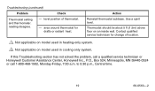
..., 7:00 a.m. Troubleshooting (continued) Problem Check Thermostat setting and thermometer. reading disagree. - area around thermostat for change of thermostat. - Use a spirit level. Thermostat should be about 5 ft (1.5m) above floor on model used in heating-only system. 2 Not applicable on an inside wall. Contact qualified service technician for drafts or radiant heat. to 5:30 p.m., Central time. 19 69-0563-2 level position of location. 1 Not applicable on model used in cooling-only...
..., 7:00 a.m. Troubleshooting (continued) Problem Check Thermostat setting and thermometer. reading disagree. - area around thermostat for change of thermostat. - Use a spirit level. Thermostat should be about 5 ft (1.5m) above floor on model used in heating-only system. 2 Not applicable on an inside wall. Contact qualified service technician for drafts or radiant heat. to 5:30 p.m., Central time. 19 69-0563-2 level position of location. 1 Not applicable on model used in cooling-only...
Owner's Manual
Page 20
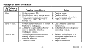
... proper secondary voltage. 1. Use additional (separate) transformer. 2. Voltage at Timer Terminals Ac Voltage at C-R Terminals Possible Cause Check 0 Vac 1. Restore power. 2. Additional (separate) transformer used to 30 Vac. 1. Replace wiring. 3. Limit switch contacts stuck open. 4. System transformer used to power the timer has inadequate voltage. 15 to power the timer is burned out. Replace transformer. 1. Rebend spring fingers to a 45 degree angle to 15 Vac. 1. Install transformer with subbase terminals. 2. Replace thermostat. 20...
... proper secondary voltage. 1. Use additional (separate) transformer. 2. Voltage at Timer Terminals Ac Voltage at C-R Terminals Possible Cause Check 0 Vac 1. Restore power. 2. Additional (separate) transformer used to 30 Vac. 1. Replace wiring. 3. Limit switch contacts stuck open. 4. System transformer used to power the timer has inadequate voltage. 15 to power the timer is burned out. Replace transformer. 1. Rebend spring fingers to a 45 degree angle to 15 Vac. 1. Install transformer with subbase terminals. 2. Replace thermostat. 20...
Owner's Manual
Page 21
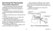
..., follow the procedure below. Set the thermostat cover on it until both thermometers read the same. Be careful not to sense area temperature, then compare the readings. Remove thermostat cover and open the flipup cover. If the readings are the same, replace cover and put the system into operation. Servicing The Thermostat Thermometer Adjustment The thermometer has been accurately calibrated at least five minutes for...
..., follow the procedure below. Set the thermostat cover on it until both thermometers read the same. Be careful not to sense area temperature, then compare the readings. Remove thermostat cover and open the flipup cover. If the readings are the same, replace cover and put the system into operation. Servicing The Thermostat Thermometer Adjustment The thermometer has been accurately calibrated at least five minutes for...


