
Installation Guide
Page 1
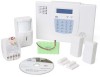
LYNXR-2 Series Security Systems Installation and Setup Guide ARMED READY OFF 1 2 3 ESCAPE AWAY RECORD 4 VOLUME 5 PLAY 6 ADD STAY LIGHTS ON 7 TEST 8 BYPASS 9 DELETE AUX LIGHTS OFF CODE 0 CHIME SELECT STATUS NO DELAY FUNCTION K15011 7/08 Rev. A
LYNXR-2 Series Security Systems Installation and Setup Guide ARMED READY OFF 1 2 3 ESCAPE AWAY RECORD 4 VOLUME 5 PLAY 6 ADD STAY LIGHTS ON 7 TEST 8 BYPASS 9 DELETE AUX LIGHTS OFF CODE 0 CHIME SELECT STATUS NO DELAY FUNCTION K15011 7/08 Rev. A

Installation Guide
Page 2
...where someone sleeps with the door partly or completely closed door. This will ensure that alarm signals can be sent to the recommendations contained in the National Fire Protection Association's (NFPA) Standard #72 noted below. • Early warning fire detection is best achieved ...an alarm in the hallway outside of each separate sleeping area, and on each additional floor of fire detection equipment in a security system. RECOMMENDATIONS FOR PROPER PROTECTION The Following Recommendations for the Location of smoke/heat detectors, we subscribe to the alarm monitoring station in...
...where someone sleeps with the door partly or completely closed door. This will ensure that alarm signals can be sent to the recommendations contained in the National Fire Protection Association's (NFPA) Standard #72 noted below. • Early warning fire detection is best achieved ...an alarm in the hallway outside of each separate sleeping area, and on each additional floor of fire detection equipment in a security system. RECOMMENDATIONS FOR PROPER PROTECTION The Following Recommendations for the Location of smoke/heat detectors, we subscribe to the alarm monitoring station in...

Installation Guide
Page 3
Table of Contents SYSTEM FEATURES ...5 MOUNTING THE CONTROL...6 WIRING CONNECTIONS...7 CONNECTING/CONFIGURING COMMUNICATIONS DEVICES 9 AC POWER AND BACKUP BATTERY...12 INSTALLING WIRELESS ZONES...14 MECHANICS OF PROGRAMMING ...17 ZONE RESPONSE TYPE DEFINITIONS 19 DATA FIELD DESCRIPTIONS... DESCRIPTORS 50 ✻85 RECORD CUSTOM VOICE DESCRIPTORS 52 REMOTE PROGRAMMING/CONTROL (DOWNLOADING 53 SYSTEM OPERATION...55 KEYPAD FUNCTION SUMMARY...60 TESTING THE SYSTEM ...61 SYSTEM COMMUNICATION ...62 TROUBLESHOOTING GUIDE ...65 PROGRAMMING DEFAULT TABLES...68 LYNXR-2 CONTROL DEFAULTS ...68 LYNXR...
Table of Contents SYSTEM FEATURES ...5 MOUNTING THE CONTROL...6 WIRING CONNECTIONS...7 CONNECTING/CONFIGURING COMMUNICATIONS DEVICES 9 AC POWER AND BACKUP BATTERY...12 INSTALLING WIRELESS ZONES...14 MECHANICS OF PROGRAMMING ...17 ZONE RESPONSE TYPE DEFINITIONS 19 DATA FIELD DESCRIPTIONS... DESCRIPTORS 50 ✻85 RECORD CUSTOM VOICE DESCRIPTORS 52 REMOTE PROGRAMMING/CONTROL (DOWNLOADING 53 SYSTEM OPERATION...55 KEYPAD FUNCTION SUMMARY...60 TESTING THE SYSTEM ...61 SYSTEM COMMUNICATION ...62 TROUBLESHOOTING GUIDE ...65 PROGRAMMING DEFAULT TABLES...68 LYNXR-2 CONTROL DEFAULTS ...68 LYNXR...

Installation Guide
Page 5
... • Macro/ 1-button paging • RF jam detection • Remote phone control • Compatible with encrypted (high-security) devices ALARM OUTPUT • Built-in EEROM • Can be uploaded, downloaded or controlled via IBM-compatible computer using Compass...) is installed. LYNXR-2 Series Installation and Setup Guide System Features UL LYNXR-2 Series is not intended for user recorded messages) • Voice announcement of this system. The LYNXR-2 Series control is a self-contained, rechargeable wireless control/communicator that features easy installation and usage.
... • Macro/ 1-button paging • RF jam detection • Remote phone control • Compatible with encrypted (high-security) devices ALARM OUTPUT • Built-in EEROM • Can be uploaded, downloaded or controlled via IBM-compatible computer using Compass...) is installed. LYNXR-2 Series Installation and Setup Guide System Features UL LYNXR-2 Series is not intended for user recorded messages) • Voice announcement of this system. The LYNXR-2 Series control is a self-contained, rechargeable wireless control/communicator that features easy installation and usage.

Installation Guide
Page 6
... the back plate by gently twisting. 3. Carefully disconnect the ribbon cable from the terminal strip board. Use the two supplied screws to secure the control panel to the front assembly PC board connector (properly aligning the red wire). 6. Slide the control panel onto the mounting...Installation and Setup Guide Mounting the Control Wall Mounting The illustration below shows the front assembly separated from the back plate. The back plate contains the terminal block for making connections to a sturdy wall, feeding the field wiring through the bottom of the mounting base, using one ...
... the back plate by gently twisting. 3. Carefully disconnect the ribbon cable from the terminal strip board. Use the two supplied screws to secure the control panel to the front assembly PC board connector (properly aligning the red wire). 6. Slide the control panel onto the mounting...Installation and Setup Guide Mounting the Control Wall Mounting The illustration below shows the front assembly separated from the back plate. The back plate contains the terminal block for making connections to a sturdy wall, feeding the field wiring through the bottom of the mounting base, using one ...

Installation Guide
Page 7
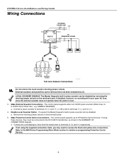
...CONNECTOR PORT STANDARD HIGH-CAPACITY BATTERY CONNECTOR LOCAL SOUNDER DISABLE 09012-009-V0 Wiring Connections 1. Secure a non-corrosive metal strap (copper is recommended) to the pipe that is electrically connected and secured to RJ31X terminals 4 (red) and 5 (green). a. Make Phone Line Connections -... TIP phone lines (typically red and green, respectively) and connect them to which the ground lead is electrically connected and secured. Connect the premises end of Connections diagram on the Lynx. LYNXR-2 Series Installation and Setup Guide Wiring Connections Wiring Overview The...
...CONNECTOR PORT STANDARD HIGH-CAPACITY BATTERY CONNECTOR LOCAL SOUNDER DISABLE 09012-009-V0 Wiring Connections 1. Secure a non-corrosive metal strap (copper is recommended) to the pipe that is electrically connected and secured to RJ31X terminals 4 (red) and 5 (green). a. Make Phone Line Connections -... TIP phone lines (typically red and green, respectively) and connect them to which the ground lead is electrically connected and secured. Connect the premises end of Connections diagram on the Lynx. LYNXR-2 Series Installation and Setup Guide Wiring Connections Wiring Overview The...
Installation Guide
Page 8
If using the supplied connection cable, you may need to reverse the black and yellow wire connections. Make External Sounder Connections - Make Powerline Carrier Device Connections - If not using these devices, they must be disabled. a. If required the Master Keypad's built-in piezo sounder can be disabled by removing the shorting jumper (shunt) on the terminal board. 5. Refer to 8 Powerline Carrier Devices. LYNXR-2 Series Installation and Setup Guide Wiring Connections RED GREY 4 5 3 6 RJ31X 2 7 1 8 INCOMING PHONE LINE RING TIP GREEN TO PREMISES PHONES...
If using the supplied connection cable, you may need to reverse the black and yellow wire connections. Make External Sounder Connections - Make Powerline Carrier Device Connections - If not using these devices, they must be disabled. a. If required the Master Keypad's built-in piezo sounder can be disabled by removing the shorting jumper (shunt) on the terminal board. 5. Refer to 8 Powerline Carrier Devices. LYNXR-2 Series Installation and Setup Guide Wiring Connections RED GREY 4 5 3 6 RJ31X 2 7 1 8 INCOMING PHONE LINE RING TIP GREEN TO PREMISES PHONES...

Installation Guide
Page 9
... LYNXR-2 Series does not support the 7845i-ENT remote access feature. Install the module into the LYNXR-2 Series back plate and secure it with the LRR/IP Communications Device being installed for the module and data in/data out connections. 3. Refer to the diagrams... COMMUNICATION PORT Installing the 7847i-L Communications Module - 9 - 09012-008-V1 It also supports upload/download programming capability via the internet using wireless (GSM) and hardwire (IP) communications modules. UL The 7845i-ENT has been evaluated by UL. Connect the provided ribbon cable between the...
... LYNXR-2 Series does not support the 7845i-ENT remote access feature. Install the module into the LYNXR-2 Series back plate and secure it with the LRR/IP Communications Device being installed for the module and data in/data out connections. 3. Refer to the diagrams... COMMUNICATION PORT Installing the 7847i-L Communications Module - 9 - 09012-008-V1 It also supports upload/download programming capability via the internet using wireless (GSM) and hardwire (IP) communications modules. UL The 7845i-ENT has been evaluated by UL. Connect the provided ribbon cable between the...

Installation Guide
Page 10
Connect the device to the Internet via the appropriate Ethernet connection, if applicable. UL AlarmNet 7845GSM and 7845i-GSM modules have not been evaluated by UL. * When available 7845GSM / TB1 7845i-GSM 1 2 ECP (+) VOLTAGE INPUT 34 GND 4 Z1/Z2 OR DATA IN 5 Z3 OR DATA OUT 6 CONTROL PANEL RED BLK YEL GRN GRN BLK RED YEL LRR/IP COMMUNICATIONS PORT DATA IN GND +12 VDC NC DATA OUT 4-WIRE CABLE (N4632-4) LYNX STANDARD CAPACITY BATTERY (OPTIONAL) REQUIRED FOR LYNX SUPER HIGH CAPACITY 24-HR BACKUP BATTERY Connecting AlarmNet 7845GSM / 7845i-GSM 09012-018-V0 7845i-ENT / 7845i ...
Connect the device to the Internet via the appropriate Ethernet connection, if applicable. UL AlarmNet 7845GSM and 7845i-GSM modules have not been evaluated by UL. * When available 7845GSM / TB1 7845i-GSM 1 2 ECP (+) VOLTAGE INPUT 34 GND 4 Z1/Z2 OR DATA IN 5 Z3 OR DATA OUT 6 CONTROL PANEL RED BLK YEL GRN GRN BLK RED YEL LRR/IP COMMUNICATIONS PORT DATA IN GND +12 VDC NC DATA OUT 4-WIRE CABLE (N4632-4) LYNX STANDARD CAPACITY BATTERY (OPTIONAL) REQUIRED FOR LYNX SUPER HIGH CAPACITY 24-HR BACKUP BATTERY Connecting AlarmNet 7845GSM / 7845i-GSM 09012-018-V0 7845i-ENT / 7845i ...

Installation Guide
Page 11
..., connect the provided shielded audio cable between the GSML/GSMVL module and the control's PC board. Insert the antenna into the control back plate and secure it with the three provided screws. 2. Configuring Long Range Radio and Internet Communication Devices 1. Enable the communications device in programming field *55 and configure alarm... cable between the GSMVL module and the control's PC board. This cable provides DC power and ground for additional information). Use double-stick tape to secure antenna to the GSML/GSMVL module. 3. If using the 7720P programmer (refer to 3.
..., connect the provided shielded audio cable between the GSML/GSMVL module and the control's PC board. Insert the antenna into the control back plate and secure it with the three provided screws. 2. Configuring Long Range Radio and Internet Communication Devices 1. Enable the communications device in programming field *55 and configure alarm... cable between the GSMVL module and the control's PC board. This cable provides DC power and ground for additional information). Use double-stick tape to secure antenna to the GSML/GSMVL module. 3. If using the 7720P programmer (refer to 3.

Installation Guide
Page 12
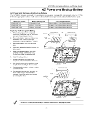
...BAT" message should clear within four hours or by a 9VAC, 25VA Plug-in Transformer, ADEMCO K10145X10 (K10145CN in the wiring diagram. 2. In addition, the system will beep once every 45 seconds to audibly indicate a low battery condition (press any key to terminals 15 and 16 as shown in Canada). Insert...have been made , snap the front assembly to fully charge. The voltage reading between terminals 15 and 16 of an AC power loss, the system is supported by a long life backup battery that is supervised for connection and for wire gauge and length. Connect wires from Transformer to Control...
...BAT" message should clear within four hours or by a 9VAC, 25VA Plug-in Transformer, ADEMCO K10145X10 (K10145CN in the wiring diagram. 2. In addition, the system will beep once every 45 seconds to audibly indicate a low battery condition (press any key to terminals 15 and 16 as shown in Canada). Insert...have been made , snap the front assembly to fully charge. The voltage reading between terminals 15 and 16 of an AC power loss, the system is supported by a long life backup battery that is supervised for connection and for wire gauge and length. Connect wires from Transformer to Control...
Installation Guide
Page 13
If required, replace the tape that secures the battery pack. 5. After the wiring connection has been made, snap the front assembly to fully charge. Rechargeable batteries may take up to 48hours to ...
If required, replace the tape that secures the battery pack. 5. After the wiring connection has been made, snap the front assembly to fully charge. Rechargeable batteries may take up to 48hours to ...

Installation Guide
Page 14
..." (Unsupervised RF) "BR" (Unsupervised Button RF) Description Sends periodic check-in those cases. The transmitter must not exceed 3 feet. The wireless system can support more unique factory-assigned input (loop) ID codes. Some transmitters, such as the 5816 and 5817, can identify a true low ..., the "missing" transmitter number(s) and "FAULT" will annunciate as a fault condition if covers are using a 5804BD/5804BDV Wireless Keypad with the system, you must be entered as described in the ✻56 Enhanced Zone Programming Mode section. 5800 Series transmitters have built-in...
..." (Unsupervised RF) "BR" (Unsupervised Button RF) Description Sends periodic check-in those cases. The transmitter must not exceed 3 feet. The wireless system can support more unique factory-assigned input (loop) ID codes. Some transmitters, such as the 5816 and 5817, can identify a true low ..., the "missing" transmitter number(s) and "FAULT" will annunciate as a fault condition if covers are using a 5804BD/5804BDV Wireless Keypad with the system, you must be entered as described in the ✻56 Enhanced Zone Programming Mode section. 5800 Series transmitters have built-in...

Installation Guide
Page 15
... transmitter's installation instructions for battery life. LYNXR-2 Series Installation and Setup Guide Installing Wireless Zones • Button-type transmitters should be checked upon installation, or in Go/No Go Test Mode. The system will enable you have a two-second delay on that the RF signal from the...keys, or two-button panic pairs • built-in keypad's two-button panic pairs Go/No Go Test Mode 5804E encrypted (High-Security) devices must physically be activated to clear the display, since they do not automatically send check-in either direction is all that is ...
... transmitter's installation instructions for battery life. LYNXR-2 Series Installation and Setup Guide Installing Wireless Zones • Button-type transmitters should be checked upon installation, or in Go/No Go Test Mode. The system will enable you have a two-second delay on that the RF signal from the...keys, or two-button panic pairs • built-in keypad's two-button panic pairs Go/No Go Test Mode 5804E encrypted (High-Security) devices must physically be activated to clear the display, since they do not automatically send check-in either direction is all that is ...

Installation Guide
Page 16
...5819, 5819S(WHS & BRS), 5828/5828V and 5850(GBD) wireless transmitters have not been evaluated by beeping two times. (3) The 5806 smoke detector must be used . (2) 5804E encrypted (High-Security) devices must be activated while the system is in SIA applications. CENTER) LOOP 3 (AUX. LOOP... input types and loop designations. LYNXR-2 Series Installation and Setup Guide Installing Wireless Zones 5800 Series Transmitter Loop Numbers (Refer to the transmitter's installation instructions for complete details. The system will confirm enrollment of the encrypted device by UL. - 16 -
...5819, 5819S(WHS & BRS), 5828/5828V and 5850(GBD) wireless transmitters have not been evaluated by beeping two times. (3) The 5806 smoke detector must be used . (2) 5804E encrypted (High-Security) devices must be activated while the system is in SIA applications. CENTER) LOOP 3 (AUX. LOOP... input types and loop designations. LYNXR-2 Series Installation and Setup Guide Installing Wireless Zones 5800 Series Transmitter Loop Numbers (Refer to the transmitter's installation instructions for complete details. The system will confirm enrollment of the encrypted device by UL. - 16 -

Installation Guide
Page 17
...one of Programming General Programming Information Programming options are four programming modes: • Data field programming (used for setting various system options). • Interactive menu mode programming (used for programming zone information, programming Powerline Carrier Devices, and for entering ...transmitter serial numbers). • Voice Prompt programming (used for setting various system options). • Pass-Thru programming (used for example, ✻21), followed by the required entry. 2. After power-...
...one of Programming General Programming Information Programming options are four programming modes: • Data field programming (used for setting various system options). • Interactive menu mode programming (used for programming zone information, programming Powerline Carrier Devices, and for entering ...transmitter serial numbers). • Voice Prompt programming (used for setting various system options). • Pass-Thru programming (used for example, ✻21), followed by the required entry. 2. After power-...

Installation Guide
Page 18
... mode using Installer Code (4112) + 888. Entering Pass-Thru Programming mode 1. Note: After exiting program mode (or upon power-up), the system takes up , enter the Installer Code (4112) + 899. 2. Refer to the Installation Instructions for the LRR/IP Communications Device being installed for... that has already been programmed into the Voice Prompt Programming mode using Installer Code (4112) + 800 or into the system will be announced whenever the system announces an event involving a zone. ✻85 Record Custom Voice Descriptors Interactive menu mode used to the default table ...
... mode using Installer Code (4112) + 888. Entering Pass-Thru Programming mode 1. Note: After exiting program mode (or upon power-up), the system takes up , enter the Installer Code (4112) + 899. 2. Refer to the Installation Instructions for the LRR/IP Communications Device being installed for... that has already been programmed into the Voice Prompt Programming mode using Installer Code (4112) + 800 or into the system will be announced whenever the system announces an event involving a zone. ✻85 Record Custom Voice Descriptors Interactive menu mode used to the default table ...

Installation Guide
Page 19
... faulting the entry/exit zone) to reach the keypad. Zone Characteristics: • Instant alarm, when armed in personal emergencies or to a zone containing monitoring devices (i.e.: water or temperature sensors, etc.). Zone type 08 is faulted first. • Instant alarm in all sensors or contacts on the...01 is not used to program a zone that one must assign a zone type to each zone, which defines the way in which the system responds to a zone containing a button for a garage, loading dock, or basement door). Type 00 Zone type 00 is used . with-delay (type 10) ...
... faulting the entry/exit zone) to reach the keypad. Zone Characteristics: • Instant alarm, when armed in personal emergencies or to a zone containing monitoring devices (i.e.: water or temperature sensors, etc.). Zone type 08 is faulted first. • Instant alarm in all sensors or contacts on the...01 is not used to program a zone that one must assign a zone type to each zone, which defines the way in which the system responds to a zone containing a button for a garage, loading dock, or basement door). Type 00 Zone type 00 is used . with-delay (type 10) ...

Installation Guide
Page 20
...active and cannot be bypassed. Zone Characteristics: • Exit delay regardless of the control panel. Zone Characteristics: • System is sent to any wireless zone with a carbon monoxide detector. Type 16 Supervised Fire with Verification Zone type 16 can be assigned to the central station...fire zone will also be provided if that zone is a special-purpose zone type used with 5800 series wireless pushbutton. Zone Characteristics: • Disarms the system when the zone is alarmed. LYNXR-2 Series Installation and Setup Guide Zone Response Type Definitions Type 09 ...
...active and cannot be bypassed. Zone Characteristics: • Exit delay regardless of the control panel. Zone Characteristics: • System is sent to any wireless zone with a carbon monoxide detector. Type 16 Supervised Fire with Verification Zone type 16 can be assigned to the central station...fire zone will also be provided if that zone is a special-purpose zone type used with 5800 series wireless pushbutton. Zone Characteristics: • Disarms the system when the zone is alarmed. LYNXR-2 Series Installation and Setup Guide Zone Response Type Definitions Type 09 ...

Installation Guide
Page 21
...the one specified will substitute the default value for procedure. See "Master Code" in Programming mode. If enabled, security code is used , a House ID Code MUST be entered, and the keypad should be displayed after inactivity .... This option allows the installer to define the specific zones intended to chime when faulted while the system is initiated. LYNXR-2 Series Installation and Setup Guide Data Field Descriptions The following pages list all wireless keypad usage 01-31 = House ID ✻25 Powerline Carrier Device 0 = A 1 = B 2 = C 3 = D (X10) House ID 4 = E 8 = I 5 = F ...
...the one specified will substitute the default value for procedure. See "Master Code" in Programming mode. If enabled, security code is used , a House ID Code MUST be entered, and the keypad should be displayed after inactivity .... This option allows the installer to define the specific zones intended to chime when faulted while the system is initiated. LYNXR-2 Series Installation and Setup Guide Data Field Descriptions The following pages list all wireless keypad usage 01-31 = House ID ✻25 Powerline Carrier Device 0 = A 1 = B 2 = C 3 = D (X10) House ID 4 = E 8 = I 5 = F ...