User Guide
Page 2
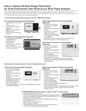
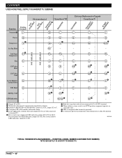
... performance. • Attractive styling complements any "frills". • Electromechanical. • Two heat/one cool; Honeywell heat pump thermostats are located on the lower edge of heat pump thermostats. NON-PROGRAMMABLE HEAT PUMP THERMOSTATS T841 Standard Non-Programmable Thermostat • Good performance without any décor. • Two heat/one cool; manual changeover eliminates unexpected system operation. • Large digital display for quick...
... performance. • Attractive styling complements any "frills". • Electromechanical. • Two heat/one cool; Honeywell heat pump thermostats are located on the lower edge of heat pump thermostats. NON-PROGRAMMABLE HEAT PUMP THERMOSTATS T841 Standard Non-Programmable Thermostat • Good performance without any décor. • Two heat/one cool; manual changeover eliminates unexpected system operation. • Large digital display for quick...
User Guide
Page 4
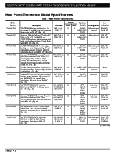
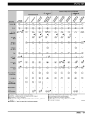
.... 25). W1,W2,W3, G,Y,R,O,B, E,X,X2,L Stages Systems Heat Cool Switch Changeover 2 1 EM.HT.- EM.HT., AUX. COOL 2 1 HEAT-OFF- or cool AUX.HT. COOL 2 1 OFF- HEAT- AUTO- HEAT PUMP THERMOSTAT CROSS REFERENCE/SELECTION GUIDE Heat Pump Thermostat Model Specifications Table 1. No auto fan in EM. Fixed B,O,R,X,E anticipation except Stage 2, which is adjustable. (Fig. 19). Same as Y594G1419, except Premier White™; HT. (Fig. 18...
.... 25). W1,W2,W3, G,Y,R,O,B, E,X,X2,L Stages Systems Heat Cool Switch Changeover 2 1 EM.HT.- EM.HT., AUX. COOL 2 1 HEAT-OFF- or cool AUX.HT. COOL 2 1 OFF- HEAT- AUTO- HEAT PUMP THERMOSTAT CROSS REFERENCE/SELECTION GUIDE Heat Pump Thermostat Model Specifications Table 1. No auto fan in EM. Fixed B,O,R,X,E anticipation except Stage 2, which is adjustable. (Fig. 19). Same as Y594G1419, except Premier White™; HT. (Fig. 18...
User Guide
Page 6
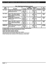
Order Number Description Terminals Stages Systems Heat Cool Switch Changeover T8611G2002 TRADELINE®; O/B,X1,X2, OT,OT 1 EM.HT.- Automatica HEAT-OFF- Automatica HEAT-OFF- R,O/B,C,X1, X2,OT,OT 2 EM.HT.- AUX,E,Y2, W2,L 2 EM.HT.-..., 2 capability. AUTO- b SYSTEM LED lights when heating or cooling equipment is applies to HVAC maintenance or service needs. COOL T8611M2017 TRADELINE®; d EM. HEAT PUMP THERMOSTAT CROSS REFERENCE/SELECTION GUIDE Table 1. COOL T8611G2028 Same as T8611M2017 except Premier Y1,Y2,W2, 3 White™, 7-day program ...
Order Number Description Terminals Stages Systems Heat Cool Switch Changeover T8611G2002 TRADELINE®; O/B,X1,X2, OT,OT 1 EM.HT.- Automatica HEAT-OFF- Automatica HEAT-OFF- R,O/B,C,X1, X2,OT,OT 2 EM.HT.- AUX,E,Y2, W2,L 2 EM.HT.-..., 2 capability. AUTO- b SYSTEM LED lights when heating or cooling equipment is applies to HVAC maintenance or service needs. COOL T8611M2017 TRADELINE®; d EM. HEAT PUMP THERMOSTAT CROSS REFERENCE/SELECTION GUIDE Table 1. COOL T8611G2028 Same as T8611M2017 except Premier Y1,Y2,W2, 3 White™, 7-day program ...
User Guide
Page 7
... -stage cool in the heater. Y594G models have automatic changeover; Added to a certain amount of droop under high loads, there can be a fairly large offset between the setpoint temperature and the room temperature. This reduces the call for specific heat pump applications. When this section also explains some of the heat pump thermostats that Honeywell manufactures...
... -stage cool in the heater. Y594G models have automatic changeover; Added to a certain amount of droop under high loads, there can be a fairly large offset between the setpoint temperature and the room temperature. This reduces the call for specific heat pump applications. When this section also explains some of the heat pump thermostats that Honeywell manufactures...
User Guide
Page 8
...HEAT PUMP THERMOSTAT CROSS REFERENCE/SELECTION GUIDE T8511 Deluxe Electronic Heat Pump Thermostats The T8511 models control two-stage heat and one -stage cool control for heat pump systems, using manual changeover. First stage heat anticipation is wired to three-stage heat and two-stage cool control for heat... cph. All programs and setpoints are available with electric heat or fossil fuel while providing optimum comfort. First stage heat anticipation is a three-stage heat/two-stage cool thermostat used to the high-speed compressor terminal.a 4. Connect ...
...HEAT PUMP THERMOSTAT CROSS REFERENCE/SELECTION GUIDE T8511 Deluxe Electronic Heat Pump Thermostats The T8511 models control two-stage heat and one -stage cool control for heat pump systems, using manual changeover. First stage heat anticipation is wired to three-stage heat and two-stage cool control for heat... cph. All programs and setpoints are available with electric heat or fossil fuel while providing optimum comfort. First stage heat anticipation is a three-stage heat/two-stage cool thermostat used to the high-speed compressor terminal.a 4. Connect ...

User Guide
Page 15
... by being drawn in the open position with an arrow indicating operation with OFF-COOL AUTO-HEAT-EM. Circuit descriptions and terminology are defined as indoor temperature changes. C/O-Changeover (heat pumps). Cool changeover valve-operates on heating. C1-Stage 1 Cooling. All T874 Multistage Thermostats use mercury switches. Manual changeover-requires a system switch movement to hookup symbols. 70-6627...
... by being drawn in the open position with an arrow indicating operation with OFF-COOL AUTO-HEAT-EM. Circuit descriptions and terminology are defined as indoor temperature changes. C/O-Changeover (heat pumps). Cool changeover valve-operates on heating. C1-Stage 1 Cooling. All T874 Multistage Thermostats use mercury switches. Manual changeover-requires a system switch movement to hookup symbols. 70-6627...

User Guide
Page 17
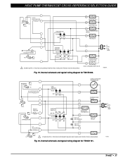
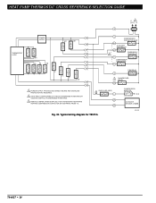
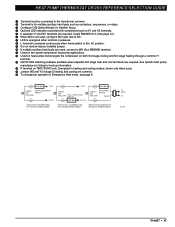
...RED) B RTD 1 RD EM. HT. Internal schematic and typical wiring diagram for T841A1308. 70-6627 • 15 W2 AUX. HEAT PUMP THERMOSTAT CROSS REFERENCE/SELECTION GUIDE Typical System Hookup Diagrams L1 L2 (HOT) RTD 1 1 ODT 1 H1 C1 FALL H1/C1 ANTICIPATOR FAN SWITCH... H2 FALL 2 EM. HT. HT. PROVIDE DISCONNECT MEANS AND OVERLOAD PROTECTION AS REQUIRED. 2 NO AUTO FAN IN EMERGENCY HEAT. LED (GREEN) E L EM. HT. HEAT OFF COOL SYSTEM SWITCH 1 POWER SUPPLY. RELAY SYSTEM MONITOR X LACO Y HEAT CHANGEOVER VALVE COMPRESSOR CONTACTOR O COOL CHANGEOVER VALVE CHP M6060A Fig. 16.
...RED) B RTD 1 RD EM. HT. Internal schematic and typical wiring diagram for T841A1308. 70-6627 • 15 W2 AUX. HEAT PUMP THERMOSTAT CROSS REFERENCE/SELECTION GUIDE Typical System Hookup Diagrams L1 L2 (HOT) RTD 1 1 ODT 1 H1 C1 FALL H1/C1 ANTICIPATOR FAN SWITCH... H2 FALL 2 EM. HT. HT. PROVIDE DISCONNECT MEANS AND OVERLOAD PROTECTION AS REQUIRED. 2 NO AUTO FAN IN EMERGENCY HEAT. LED (GREEN) E L EM. HT. HEAT OFF COOL SYSTEM SWITCH 1 POWER SUPPLY. RELAY SYSTEM MONITOR X LACO Y HEAT CHANGEOVER VALVE COMPRESSOR CONTACTOR O COOL CHANGEOVER VALVE CHP M6060A Fig. 16.
User Guide
Page 18
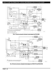
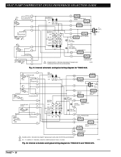
...THERMOSTAT X2 T OUTDOOR O THERMISTOR COOL CHANGEOVER RELAY COMPRESSOR CONTACTOR Y 2 FIELD REMOVABLE JUMPER. 3 AUTO FAN IN EMERGENCY HEAT. Internal schematic and typical wiring diagram for T841A1712 and T841A1738. HEAT LED (RED) W3 RELAY COOL CHANGEOVER RELAY G R E X AUX. HEAT RELAY B HEAT CHANGEOVER RELAY COMPRESSOR CONTACTOR Y Fig. 18. Fig. 17. HEAT...6 FALL H2 12 H2 ANTICIPATOR 11 FAN SWITCH AUTO ON SYSTEM SWITCH EM. HEAT LED (RED) FAN RELAY 2 F AUX. HEAT OFF COOL 1 POWER SUPPLY. HEAT RELAY AUX. L2 1 L1 (HOT) M13249 70-6627 • 16 PROVIDE...
...THERMOSTAT X2 T OUTDOOR O THERMISTOR COOL CHANGEOVER RELAY COMPRESSOR CONTACTOR Y 2 FIELD REMOVABLE JUMPER. 3 AUTO FAN IN EMERGENCY HEAT. Internal schematic and typical wiring diagram for T841A1712 and T841A1738. HEAT LED (RED) W3 RELAY COOL CHANGEOVER RELAY G R E X AUX. HEAT RELAY B HEAT CHANGEOVER RELAY COMPRESSOR CONTACTOR Y Fig. 18. Fig. 17. HEAT...6 FALL H2 12 H2 ANTICIPATOR 11 FAN SWITCH AUTO ON SYSTEM SWITCH EM. HEAT LED (RED) FAN RELAY 2 F AUX. HEAT OFF COOL 1 POWER SUPPLY. HEAT RELAY AUX. L2 1 L1 (HOT) M13249 70-6627 • 16 PROVIDE...
User Guide
Page 19
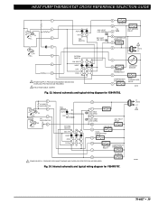
R L1 (HOT) L2 1 X Y1 COMPRESSOR CONTACTOR O COOL CHANGEOVER VALVE M6068A Fig. 19. Internal schematic and typical wiring diagram for Y594G1161. HT. Fig. 20. Internal schematic and typical wiring diagram for T841B1000... OUTDOOR THERMISTOR T FAN RELAY G CHANGEOVER VALVE O R X2 OUTDOOR THERMOSTAT W AUX. HEAT PUMP THERMOSTAT CROSS REFERENCE/SELECTION GUIDE H1/C1 ANTICIPATOR H1 C1 FALL FAN SWITCH AUTO ON W1 HEAT RELAY 1 W2 HEAT RELAY 2 B HEAT CHANGEOVER VALVE G FAN RELAY H2 ANTICIPATOR H2 FALL SYSTEM SWITCH HEAT OFF COOL 1 POWER SUPPLY. L1 (HOT) L2 1 M1593 70-6627 &#...
R L1 (HOT) L2 1 X Y1 COMPRESSOR CONTACTOR O COOL CHANGEOVER VALVE M6068A Fig. 19. Internal schematic and typical wiring diagram for Y594G1161. HT. Fig. 20. Internal schematic and typical wiring diagram for T841B1000... OUTDOOR THERMISTOR T FAN RELAY G CHANGEOVER VALVE O R X2 OUTDOOR THERMOSTAT W AUX. HEAT PUMP THERMOSTAT CROSS REFERENCE/SELECTION GUIDE H1/C1 ANTICIPATOR H1 C1 FALL FAN SWITCH AUTO ON W1 HEAT RELAY 1 W2 HEAT RELAY 2 B HEAT CHANGEOVER VALVE G FAN RELAY H2 ANTICIPATOR H2 FALL SYSTEM SWITCH HEAT OFF COOL 1 POWER SUPPLY. L1 (HOT) L2 1 M1593 70-6627 &#...
User Guide
Page 20
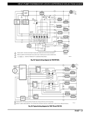
... 2 COMPRESSOR CONTACTOR Y1 1 POWER SUPPLY. Y1 JUMPER IS Y TERMINAL; RELAY L EM. HEAT AUTO COOL W2 E AUX. RELAY AUX. M8703 Fig. 22. LED (RED) X AUX. Internal schematic and typical wiring diagram for Y594G1419 and Y594G1476. 70-6627 • 18 HT. HEAT PUMP THERMOSTAT CROSS REFERENCE/SELECTION GUIDE FALL 1 H1 ANTICIPATOR 2 H1 4 6 H2 ANTICIPATOR H2 FALL...
... 2 COMPRESSOR CONTACTOR Y1 1 POWER SUPPLY. Y1 JUMPER IS Y TERMINAL; RELAY L EM. HEAT AUTO COOL W2 E AUX. RELAY AUX. M8703 Fig. 22. LED (RED) X AUX. Internal schematic and typical wiring diagram for Y594G1419 and Y594G1476. 70-6627 • 18 HT. HEAT PUMP THERMOSTAT CROSS REFERENCE/SELECTION GUIDE FALL 1 H1 ANTICIPATOR 2 H1 4 6 H2 ANTICIPATOR H2 FALL...
User Guide
Page 21
... schematic and typical wiring diagram for Y594R1797. HEAT OFF R L EM. HEAT RELAY W2 FAN RELAY G COOL CHANGEOVER VALVE O COOL E COMPRESSOR EM. L1 (HOT) L2 1 M8700 70-6627 • 19 HEAT CONTACTOR RELAY Y "B" RELAY B 1 POWER SUPPLY. Fig. 24. HEAT HEAT OFF COOL 1 POWER SUPPLY. HEAT LED (RED) G FAN RELAY W 2 U AUX. HEAT LED (GRN) AUX. HEAT PUMP THERMOSTAT CROSS REFERENCE/SELECTION GUIDE 1 2 H1 C1...
... schematic and typical wiring diagram for Y594R1797. HEAT OFF R L EM. HEAT RELAY W2 FAN RELAY G COOL CHANGEOVER VALVE O COOL E COMPRESSOR EM. L1 (HOT) L2 1 M8700 70-6627 • 19 HEAT CONTACTOR RELAY Y "B" RELAY B 1 POWER SUPPLY. Fig. 24. HEAT HEAT OFF COOL 1 POWER SUPPLY. HEAT LED (RED) G FAN RELAY W 2 U AUX. HEAT LED (GRN) AUX. HEAT PUMP THERMOSTAT CROSS REFERENCE/SELECTION GUIDE 1 2 H1 C1...
User Guide
Page 22
... typical wiring diagram for Y594R1425. 70-6627 • 20 HEAT PUMP THERMOSTAT CROSS REFERENCE/SELECTION GUIDE W3 W3 RELAY H1 ANTICIPATOR 1 C ANTICIPATOR 2 FAN SWITCH AUTO ON H1 3 C FALL 4 5 H2 ANTICIPATOR H2 6 FALL SYSTEM SWITCH EM. HEAT OFF COOL 11 1 POWER SUPPLY. LED (GRN) W2 AUX. O COOL CHANGEOVER VALVE L COMPRESSOR MONITOR FAN RELAY G R EM. PROVIDE DISCONNECT...
... typical wiring diagram for Y594R1425. 70-6627 • 20 HEAT PUMP THERMOSTAT CROSS REFERENCE/SELECTION GUIDE W3 W3 RELAY H1 ANTICIPATOR 1 C ANTICIPATOR 2 FAN SWITCH AUTO ON H1 3 C FALL 4 5 H2 ANTICIPATOR H2 6 FALL SYSTEM SWITCH EM. HEAT OFF COOL 11 1 POWER SUPPLY. LED (GRN) W2 AUX. O COOL CHANGEOVER VALVE L COMPRESSOR MONITOR FAN RELAY G R EM. PROVIDE DISCONNECT...
User Guide
Page 25
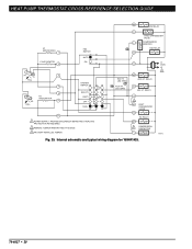
... OVERLOAD PROTECTION AS REQUIRED. 2 REMOVE JUMPER FOR SYSTEM WITH ISOLATED STAGE 1 HEATING AND COOLING CONNECTIONS. 3 DENOTES THERMOSTAT TO SUBBASE INTERCONNECT. M11333 Fig. 29. RELAY E STAGE 1 HEAT RELAY W1 FAN RELAY G COOL 1 HEAT 1 O 2 COOL CHANGEOVER VALVE B HEAT CHANGEOVER VALVE Y1 COMPRESSOR CONTACTOR P 1 POWER SUPPLY. L1 (HOT) L2 1 THERMISTOR SENSOR THERMOSTAT LOGIC STAGE 2 RELAY STAGE 1 RELAY SYSTEM SWITCH EM. HT. HT. DEFROST CONTROL M6019A Fig...
... OVERLOAD PROTECTION AS REQUIRED. 2 REMOVE JUMPER FOR SYSTEM WITH ISOLATED STAGE 1 HEATING AND COOLING CONNECTIONS. 3 DENOTES THERMOSTAT TO SUBBASE INTERCONNECT. M11333 Fig. 29. RELAY E STAGE 1 HEAT RELAY W1 FAN RELAY G COOL 1 HEAT 1 O 2 COOL CHANGEOVER VALVE B HEAT CHANGEOVER VALVE Y1 COMPRESSOR CONTACTOR P 1 POWER SUPPLY. L1 (HOT) L2 1 THERMISTOR SENSOR THERMOSTAT LOGIC STAGE 2 RELAY STAGE 1 RELAY SYSTEM SWITCH EM. HT. HT. DEFROST CONTROL M6019A Fig...
User Guide
Page 26
CHECK LED (RED) L OT OT Fig. 30. HEAT PUMP THERMOSTAT CROSS REFERENCE/SELECTION GUIDE L1 1 (HOT) L2 R THERMOSTAT LOGIC POWER SUPPLY W2 W1 E Y1 G O/B W2 W1 C COMPRESSOR CONTACTOR HEAT W1 AUXILIARY HEAT RELAY W2 3 EMERGENCY HEAT RELAY E COMPRESSOR CONTACTOR Y1 E Y1 G O/B FAN RELAY G 2 CHANGEOVER... PROTECTION AS REQUIRED. 2 O/B IS FIELD CONFIGURABLE TO SELECT ENERGIZED IN HEATING OR COOLING. (DEFAULT IS ENERGIZED IN HEATING). 3 REMOVE JUMPER, WHEN SUPPLIED, FOR SYSTEMS WITH SEPARATE HEATING COMPRESSOR CONTACTOR (W1 SEPARATE FROM Y1). Typical wiring diagram for T8511G.
CHECK LED (RED) L OT OT Fig. 30. HEAT PUMP THERMOSTAT CROSS REFERENCE/SELECTION GUIDE L1 1 (HOT) L2 R THERMOSTAT LOGIC POWER SUPPLY W2 W1 E Y1 G O/B W2 W1 C COMPRESSOR CONTACTOR HEAT W1 AUXILIARY HEAT RELAY W2 3 EMERGENCY HEAT RELAY E COMPRESSOR CONTACTOR Y1 E Y1 G O/B FAN RELAY G 2 CHANGEOVER... PROTECTION AS REQUIRED. 2 O/B IS FIELD CONFIGURABLE TO SELECT ENERGIZED IN HEATING OR COOLING. (DEFAULT IS ENERGIZED IN HEATING). 3 REMOVE JUMPER, WHEN SUPPLIED, FOR SYSTEMS WITH SEPARATE HEATING COMPRESSOR CONTACTOR (W1 SEPARATE FROM Y1). Typical wiring diagram for T8511G.
User Guide
Page 28
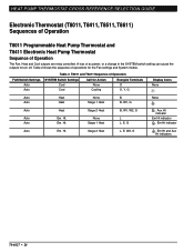
..., T8611) Sequences of Operation T8011 Programmable Heat Pump Thermostat and T8411 Electronic Heat Pump Thermostat Sequence of operations for Action Energize Terminals Cool Cool None Cooling O O, Y, G Display Icons None Auto Auto Heat Heat None Stage 1 Heat B B, W1, G None Auto Auto Auto Heat Em. Ht. Table 2 shows the sequence of Operation The Fan, Heat and Cool outputs are relay controlled. Stage 2 Heat L, E, W2, G , Em Ht and Aux...
..., T8611) Sequences of Operation T8011 Programmable Heat Pump Thermostat and T8411 Electronic Heat Pump Thermostat Sequence of operations for Action Energize Terminals Cool Cool None Cooling O O, Y, G Display Icons None Auto Auto Heat Heat None Stage 1 Heat B B, W1, G None Auto Auto Auto Heat Em. Ht. Table 2 shows the sequence of Operation The Fan, Heat and Cool outputs are relay controlled. Stage 2 Heat L, E, W2, G , Em Ht and Aux...
User Guide
Page 31
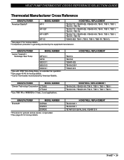
... DSP600 a Provision for 3 heat, 2 cool applications. b See pages 42-45 for hookup details. HONEYWELL REPLACEMENT T841A1001a T841A1001a T874W1031/Q674L1546, Y594W1014 70-6627 • 29 b Compressor protection is generally provided by American Stabilis. b See page 49 for hookup details. c Carrier thermostats manufactured by the equipment manufacturer. HEAT PUMP THERMOSTAT CROSS REFERENCE/SELECTION GUIDE Thermostat Manufacturer Cross Reference MANUFACTURER...
... DSP600 a Provision for 3 heat, 2 cool applications. b See pages 42-45 for hookup details. HONEYWELL REPLACEMENT T841A1001a T841A1001a T874W1031/Q674L1546, Y594W1014 70-6627 • 29 b Compressor protection is generally provided by American Stabilis. b See page 49 for hookup details. c Carrier thermostats manufactured by the equipment manufacturer. HEAT PUMP THERMOSTAT CROSS REFERENCE/SELECTION GUIDE Thermostat Manufacturer Cross Reference MANUFACTURER...
User Guide
Page 35
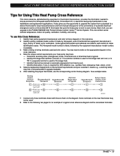
... model number, if available. 3. The Honeywell model number is used for first stage heat and cool, or to the following two pages for an example of all, you the opportunity to upgrade the system from a standard to a deluxe thermostat for improved performance and from heat to C R M13251 7. Make a listing of automatic heat/cool changeover and to a Chronotherm®...
... model number, if available. 3. The Honeywell model number is used for first stage heat and cool, or to the following two pages for an example of all, you the opportunity to upgrade the system from a standard to a deluxe thermostat for improved performance and from heat to C R M13251 7. Make a listing of automatic heat/cool changeover and to a Chronotherm®...
User Guide
Page 37
HEAT PUMP THERMOSTAT CROSS REFERENCE/SELECTION GUIDE ³ Terminal must be connected to the transformer common. · Terminal is for hookup information. ƹ P terminal on both first stage cooling and first stage heating through a common Y terminal. Ƹ Q674F1022 switching subbase available when separate first stage heat and cool terminals are required. Energized in Emergency Heat mode, see page 9. shown only when...
HEAT PUMP THERMOSTAT CROSS REFERENCE/SELECTION GUIDE ³ Terminal must be connected to the transformer common. · Terminal is for hookup information. ƹ P terminal on both first stage cooling and first stage heating through a common Y terminal. Ƹ Q674F1022 switching subbase available when separate first stage heat and cool terminals are required. Energized in Emergency Heat mode, see page 9. shown only when...
User Guide
Page 46
...L to X1, jumper X2 to C. ¿ Configure O/B (select models) in Em. position. HONEYWELL MODEL NUMBER (CUSTOMER PART NUMBER) T874D1264/Q674L1116 (HH07AT173/HH93AZ171) 70-6627 • 44 Cool - Ht. Heat 2nd Stage Compressor - ´ Y1 W1 - - - - For system monitor LED indication, connect L to ... is in AUTO position, equipment operates in cool mode only. ¾ LED is energized when terminal is powered. µ L terminal is powered continuously when thermostat is in Installer Setup. ´ In this application, auxiliary heat and compressor two are connected to E.
...L to X1, jumper X2 to C. ¿ Configure O/B (select models) in Em. position. HONEYWELL MODEL NUMBER (CUSTOMER PART NUMBER) T874D1264/Q674L1116 (HH07AT173/HH93AZ171) 70-6627 • 44 Cool - Ht. Heat 2nd Stage Compressor - ´ Y1 W1 - - - - For system monitor LED indication, connect L to ... is in AUTO position, equipment operates in cool mode only. ¾ LED is energized when terminal is powered. µ L terminal is powered continuously when thermostat is in Installer Setup. ´ In this application, auxiliary heat and compressor two are connected to E.
User Guide
Page 51
... W3 W3 - LED Indication - - - - - - - - C R Y/W1 - ¾ Aux. - G Y2 ³ O/B ³ O/B L E - - - X1 X2 ³ Configure O/B (select models) in Installer Setup. · Both first stage heat and cool are connected to HP terminal. » If provided on original equipment. ¿ Terminal is not used, configure W2 cycle rate to transformer common. ² Optional ...
... W3 W3 - LED Indication - - - - - - - - C R Y/W1 - ¾ Aux. - G Y2 ³ O/B ³ O/B L E - - - X1 X2 ³ Configure O/B (select models) in Installer Setup. · Both first stage heat and cool are connected to HP terminal. » If provided on original equipment. ¿ Terminal is not used, configure W2 cycle rate to transformer common. ² Optional ...


