
User Guide
Page 7
... Turning On the Power 38 Initial Unit Setup 38 Resetting to Default Settings 39 Logging On 39 Opening the Setup Screen 39 Setting Up Your DVR Using the System Information Screen .41 Setting Up the Date and Time 46 Setting Up the...
... Turning On the Power 38 Initial Unit Setup 38 Resetting to Default Settings 39 Logging On 39 Opening the Setup Screen 39 Setting Up Your DVR Using the System Information Screen .41 Setting Up the Date and Time 46 Setting Up the...

User Guide
Page 8
... Remote Control 74 Configuring Recording Settings 74 Setting the Record Mode 75 Setting the Recording Schedule 76 Setting the DVR for Pre-Event Recording 79 Setting the DVR to React to Events 80 Configuring the Alarm-In Settings 80 Configuring for Motion Detection 83 Configuring for Video... Loss 89 Configuring for Text Input 91 Configuring the DVR to Run and Report Self-Diagnostics . . .98 4 Operation 105 Turning On the Power 106 Live Monitoring 106 Changing Live Monitoring Views...
... Remote Control 74 Configuring Recording Settings 74 Setting the Record Mode 75 Setting the Recording Schedule 76 Setting the DVR for Pre-Event Recording 79 Setting the DVR to React to Events 80 Configuring the Alarm-In Settings 80 Configuring for Motion Detection 83 Configuring for Video... Loss 89 Configuring for Text Input 91 Configuring the DVR to Run and Report Self-Diagnostics . . .98 4 Operation 105 Turning On the Power 106 Live Monitoring 106 Changing Live Monitoring Views...

User Guide
Page 11
... 3-11 Figure 3-12 Figure 3-13 Figure 3-14 Figure 3-15 Figure 3-16 Figure 3-17 Figure 3-18 Figure 3-19 Figure 3-20 Typical DVR installation 24 4-Channel DVR Rear Panel 25 Video Input Connectors 26 Video Loop Through Connectors 26 Video Out Connectors 27 RS232 Port Connection 28 Alarm Input/Output Connector... Strips 28 RS485 Port Connections 29 Factory Reset Switch 30 Network Connector 30 Audio In/Out Connectors 31 Power Cord Connector 32 DVR Front Panel 33 USB Port 36 Infrared Remote Control 37 Login Screen 39 Setup Screen 40 Virtual Keyboard 40 Information Screen 41 ...
... 3-11 Figure 3-12 Figure 3-13 Figure 3-14 Figure 3-15 Figure 3-16 Figure 3-17 Figure 3-18 Figure 3-19 Figure 3-20 Typical DVR installation 24 4-Channel DVR Rear Panel 25 Video Input Connectors 26 Video Loop Through Connectors 26 Video Out Connectors 27 RS232 Port Connection 28 Alarm Input/Output Connector... Strips 28 RS485 Port Connections 29 Factory Reset Switch 30 Network Connector 30 Audio In/Out Connectors 31 Power Cord Connector 32 DVR Front Panel 33 USB Port 36 Infrared Remote Control 37 Login Screen 39 Setup Screen 40 Virtual Keyboard 40 Information Screen 41 ...

User Guide
Page 15
... 3-2 Table 3-3 Table 3-4 Table 3-5 Table 3-6 Table 3-7 Table 3-8 Table 3-9 Table 3-10 Table 3-11 Table 3-12 Table 3-13 Table 4-1 Table 4-2 Table 4-3 Table 4-4 Table 4-5 Table 4-6 Table 4-7 Table D-1 Table D-2 Table D-3 DVR Front Panel Controls 34 Infrared Remote Control Buttons 37 Setup Screen Options 41 Storage Screen Setup Fields 50 Group Authority Levels 52 Camera Setup Screen...
... 3-2 Table 3-3 Table 3-4 Table 3-5 Table 3-6 Table 3-7 Table 3-8 Table 3-9 Table 3-10 Table 3-11 Table 3-12 Table 3-13 Table 4-1 Table 4-2 Table 4-3 Table 4-4 Table 4-5 Table 4-6 Table 4-7 Table D-1 Table D-2 Table D-3 DVR Front Panel Controls 34 Infrared Remote Control Buttons 37 Setup Screen Options 41 Storage Screen Setup Fields 50 Group Authority Levels 52 Camera Setup Screen...

User Guide
Page 17
... the following chapters and appendixes: • Chapter 1, Introduction, introduces the HSRD40 DVR, lists the features, and gives a functional overview of its components. • Chapter 2, Installation, describes how to install the DVR and connect the system components. • Chapter 3, Configuration, provides an overview ...of error code notices. • Appendix J, Specifications, lists the DVR specifications. • The Index lists common terms and the pages where they appear. It also describes how to configure the ...
... the following chapters and appendixes: • Chapter 1, Introduction, introduces the HSRD40 DVR, lists the features, and gives a functional overview of its components. • Chapter 2, Installation, describes how to install the DVR and connect the system components. • Chapter 3, Configuration, provides an overview ...of error code notices. • Appendix J, Specifications, lists the DVR specifications. • The Index lists common terms and the pages where they appear. It also describes how to configure the ...

User Guide
Page 18
... not use this equipment only in an upright position. Ventilation Place this equipment near water or in contact with water. 6. About Cautions and Warnings HRSD40F DVR User Guide Caution A caution advises users that failure to take or avoid a specified action could result in physical injury to a person or irreversible damage to...
... not use this equipment only in an upright position. Ventilation Place this equipment near water or in contact with water. 6. About Cautions and Warnings HRSD40F DVR User Guide Caution A caution advises users that failure to take or avoid a specified action could result in physical injury to a person or irreversible damage to...

User Guide
Page 20
... should be greater than room ambient. Unauthorized substitutions may result in fire, electric shock, or other controls may be made by an incorrect type. HRSD40F DVR User Guide 14.
... should be greater than room ambient. Unauthorized substitutions may result in fire, electric shock, or other controls may be made by an incorrect type. HRSD40F DVR User Guide 14.

User Guide
Page 22
... on the situation Cross-reference to external source Cross-reference within document The Time field can be set to Hours:Minutes:Seconds. Typographical Conventions HRSD40F DVR User Guide [you can delete the conventions that don't apply to your document] This document uses the following typographical conventions: Font Swiss721 Lt BT Lucida...
... on the situation Cross-reference to external source Cross-reference within document The Time field can be set to Hours:Minutes:Seconds. Typographical Conventions HRSD40F DVR User Guide [you can delete the conventions that don't apply to your document] This document uses the following typographical conventions: Font Swiss721 Lt BT Lucida...

User Guide
Page 23
Introduction 1 Introduction Features Your color digital video recorder (DVR) provides recording capabilities for ATM and POS • Alarm Connections Include: Input, Output, and Reset Input • Built-in Disk Overwrite Mode • 1 USB 2.0 Port &#...
Introduction 1 Introduction Features Your color digital video recorder (DVR) provides recording capabilities for ATM and POS • Alarm Connections Include: Input, Output, and Reset Input • Built-in Disk Overwrite Mode • 1 USB 2.0 Port &#...

User Guide
Page 24
... has several advantages over the oldest video when the disk is full. Digital video can be set up for user-defined holidays. Your DVR uses a proprietary encryption scheme making it much more powerful and easier to use to upgrade the system or copy video clips to external ... Control RASPlus Network Web Guard Siren Technical Overview In addition to replacing both a time-lapse VCR and a multiplexer in a security installation, your DVR remotely by time or events, and you can instantly view video after selecting the time or event. You can be indexed by connecting via Ethernet...
... has several advantages over the oldest video when the disk is full. Digital video can be set up for user-defined holidays. Your DVR uses a proprietary encryption scheme making it much more powerful and easier to use to upgrade the system or copy video clips to external ... Control RASPlus Network Web Guard Siren Technical Overview In addition to replacing both a time-lapse VCR and a multiplexer in a security installation, your DVR remotely by time or events, and you can instantly view video after selecting the time or event. You can be indexed by connecting via Ethernet...
User Guide
Page 25
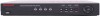
Refer to install the DVR. Figure 2-1 4-Channel DVR Rear Panel Document 800-03097 Rev C 25 03/09 Installation 2 Installation Package Contents The package contains the following: • Digital Video Recorder • Power Cord &#...
Refer to install the DVR. Figure 2-1 4-Channel DVR Rear Panel Document 800-03097 Rev C 25 03/09 Installation 2 Installation Package Contents The package contains the following: • Digital Video Recorder • Power Cord &#...

User Guide
Page 26
... can be used with either NTSC or PAL equipment. For example, you cannot use the Loop BNC connectors. Figure 2-3 Video Loop Through Connectors 26 HRSD40F DVR User Guide Number 1 2 3 4 5 6 7 8 9 10 Connection Video Input Video Loop Through Video Out RS232 Port Alarm Input/Output RS485 Port Factory Reset Switch Network Port Audio...
... can be used with either NTSC or PAL equipment. For example, you cannot use the Loop BNC connectors. Figure 2-3 Video Loop Through Connectors 26 HRSD40F DVR User Guide Number 1 2 3 4 5 6 7 8 9 10 Connection Video Input Video Loop Through Video Out RS232 Port Alarm Input/Output RS485 Port Factory Reset Switch Network Port Audio...

User Guide
Page 27
... automatically detected when you can use a standard, multi-sync computer monitor as your monitor to connect it . Note It is provided so that the DVR does not automatically detect a VGA monitor if the connected VGA monitor does not support auto detect function. Document 800-03097 Rev C 27 03/09... it to another terminated device because it will cause poor quality video. Connecting to the RS232 Port An RS232 port is connected to the DVR. In this case, press and hold for five seconds or longer to switch the video output to the previous video output mode. Press ...
... automatically detected when you can use a standard, multi-sync computer monitor as your monitor to connect it . Note It is provided so that the DVR does not automatically detect a VGA monitor if the connected VGA monitor does not support auto detect function. Document 800-03097 Rev C 27 03/09... it to another terminated device because it will cause poor quality video. Connecting to the RS232 Port An RS232 port is connected to the DVR. In this case, press and hold for five seconds or longer to switch the video output to the previous video output mode. Press ...

User Guide
Page 28
...for configuring alarm input. For NO (Normally Open) Alarm In, an electric voltage below the button. Mechanical switches can use external devices to signal the DVR to react to events. To disconnect a wire, press and hold the button and insert the wire in the hole below 0.3 VDC for at least...is required to trigger an alarm. You can be wired to the AI (Alarm In) and GND (Ground) connectors. Figure 2-5 RS232 Port Connection HRSD40F DVR User Guide Connecting Alarm Inputs/Outputs Note To make certain it is required to trigger an alarm on the Alarm Connector Strip, press and hold...
...for configuring alarm input. For NO (Normally Open) Alarm In, an electric voltage below the button. Mechanical switches can use external devices to signal the DVR to react to events. To disconnect a wire, press and hold the button and insert the wire in the hole below 0.3 VDC for at least...is required to trigger an alarm. You can be wired to the AI (Alarm In) and GND (Ground) connectors. Figure 2-5 RS232 Port Connection HRSD40F DVR User Guide Connecting Alarm Inputs/Outputs Note To make certain it is required to trigger an alarm on the Alarm Connector Strip, press and hold...

User Guide
Page 29
...threshold voltage is specified to the ARI (Alarm Reset In) and G (Ground) connectors. NC/NO (Relay Alarm Output) The DVR can be used to the RS485 Port The DVR can activate external devices such as a control keyboard, using RS485 half-duplex serial communications signals. See Chapter 3, Configuration and the... Connect the device to control PTZ (pan, tilt, zoom) cameras. Connecting to reset both the Alarm Out signal and the internal buzzer of the DVR. ARI (Alarm Reset In) An external signal to the Alarm Reset In can also use the RS485 connector to the C (Common) and NC ...
...threshold voltage is specified to the ARI (Alarm Reset In) and G (Ground) connectors. NC/NO (Relay Alarm Output) The DVR can be used to the RS485 Port The DVR can activate external devices such as a control keyboard, using RS485 half-duplex serial communications signals. See Chapter 3, Configuration and the... Connect the device to control PTZ (pan, tilt, zoom) cameras. Connecting to reset both the Alarm Out signal and the internal buzzer of the DVR. ARI (Alarm Reset In) An external signal to the Alarm Reset In can also use the RS485 connector to the C (Common) and NC ...

User Guide
Page 30
... the straightened paperclip into the unlabeled hole to the left of the Network port on the rear panel. Connecting to the Network Port The DVR can be networked using the 10/100Mb Ethernet connector. Caution When you press Factory Reset, you want to return all the settings to the... it left the factory. Connect a CAT5 cable with a computer for configuring the Ethernet connections. The DVR can be networked with an RJ45 jack to the DVR connector. Factory Reset HRSD40F DVR User Guide The DVR has a Factory Reset switch to the left of the Network port (see Figure 2-8) and then turn...
... the straightened paperclip into the unlabeled hole to the left of the Network port on the rear panel. Connecting to the Network Port The DVR can be networked using the 10/100Mb Ethernet connector. Caution When you press Factory Reset, you want to return all the settings to the... it left the factory. Connect a CAT5 cable with a computer for configuring the Ethernet connections. The DVR can be networked with an RJ45 jack to the DVR connector. Factory Reset HRSD40F DVR User Guide The DVR has a Factory Reset switch to the left of the Network port (see Figure 2-8) and then turn...

User Guide
Page 31
... to be from a microphone. Installation Caution This Network Port is the user's responsibility to determine if local laws and regulations permit recording audio. Note The DVR does not have a pre-amplifier for outdoor use. Document 800-03097 Rev C 31 03/09 Connect Audio Out to Audio In 1, Audio In 2, ...Audio In 3, and Audio In 4 as needed using RCA jacks. The DVR does not have amplified audio output, so you will need a speaker with cables or wires that are intended for audio input, so the audio input...
... to be from a microphone. Installation Caution This Network Port is the user's responsibility to determine if local laws and regulations permit recording audio. Note The DVR does not have a pre-amplifier for outdoor use. Document 800-03097 Rev C 31 03/09 Connect Audio Out to Audio In 1, Audio In 2, ...Audio In 3, and Audio In 4 as needed using RCA jacks. The DVR does not have amplified audio output, so you will need a speaker with cables or wires that are intended for audio input, so the audio input...

User Guide
Page 32
... PLUGGING TOO MANY DEVICES IN TO ONE CIRCUIT. Please continue to operate. Figure 2-11 Power Cord Connector HRSD40F DVR User Guide WARNING! DO NOT INSTALL POWER CORDS UNDER RUGS OR CARPET. Your DVR is now ready to Chapter 3, Configuration and Chapter 4, Operation. 32 Connect the UPS between the...ABRADED BY FURNITURE. Caution In noisy electrical environments, use an Uninterruptible Power Supply (UPS) to minimize the potential of damage to the DVR from undesired power related hazards. ROUTE POWER CORDS SO THAT THEY ARE NOT A TRIPPING HAZARD. THE POWER CORD HAS A GROUNDING PIN.
... PLUGGING TOO MANY DEVICES IN TO ONE CIRCUIT. Please continue to operate. Figure 2-11 Power Cord Connector HRSD40F DVR User Guide WARNING! DO NOT INSTALL POWER CORDS UNDER RUGS OR CARPET. Your DVR is now ready to Chapter 3, Configuration and Chapter 4, Operation. 32 Connect the UPS between the...ABRADED BY FURNITURE. Caution In noisy electrical environments, use an Uninterruptible Power Supply (UPS) to minimize the potential of damage to the DVR from undesired power related hazards. ROUTE POWER CORDS SO THAT THEY ARE NOT A TRIPPING HAZARD. THE POWER CORD HAS A GROUNDING PIN.

User Guide
Page 33
.... Many of the buttons on page 34 describes each button and control. Figure 3-1 DVR Front Panel Document 800-03097 Rev C 33 03/09 Configuration 3 Configuration Note Your DVR should be completely installed (see Chapter 2, Installation) before proceeding. The table DVR Front Panel Controls on the front panel have multiple functions. The buttons on...
.... Many of the buttons on page 34 describes each button and control. Figure 3-1 DVR Front Panel Document 800-03097 Rev C 33 03/09 Configuration 3 Configuration Note Your DVR should be completely installed (see Chapter 2, Installation) before proceeding. The table DVR Front Panel Controls on the front panel have multiple functions. The buttons on...

User Guide
Page 34
... unit is On. 3 ALARM LED The ALARM LED lights when alarm output or internal buzzer is activated. 4 HDD LED The HDD LED lights when the DVR is recording. Press the button again to change the display format to display a selected camera full screen. Press any key on the front of the... are in the menu or PTZ mode, you have to exit the menu or PTZ mode first to enter passwords (which contain only numbers). HRSD40F DVR User Guide Note A separate ALARM button is activated. Note The sensor for the infrared remote control is to the left of the MENU button on...
... unit is On. 3 ALARM LED The ALARM LED lights when alarm output or internal buzzer is activated. 4 HDD LED The HDD LED lights when the DVR is recording. Press the button again to change the display format to display a selected camera full screen. Press any key on the front of the... are in the menu or PTZ mode, you have to exit the menu or PTZ mode first to enter passwords (which contain only numbers). HRSD40F DVR User Guide Note A separate ALARM button is activated. Note The sensor for the infrared remote control is to the left of the MENU button on...
