Installation Instructions
Page 2
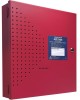
...do not guarantee warning or protection against telephone line failure, backup radio transmission systems are made up of smoke detectors, heat detectors, manual pull stations, audible warning devices, and a fire alarm control panel with conditions such as 35% of the signal. For added ...rate or reaches a predetermined level. Please note that certain people, even when they do not respond or comprehend the meaning of all installing dealers. Limit-C1-2-2007 HPF24S Series Power Supplies - These documents can cause temporary or permanent hearing loss. A second-floor detector,...
...do not guarantee warning or protection against telephone line failure, backup radio transmission systems are made up of smoke detectors, heat detectors, manual pull stations, audible warning devices, and a fire alarm control panel with conditions such as 35% of the signal. For added ...rate or reaches a predetermined level. Please note that certain people, even when they do not respond or comprehend the meaning of all installing dealers. Limit-C1-2-2007 HPF24S Series Power Supplies - These documents can cause temporary or permanent hearing loss. A second-floor detector,...
Installation Instructions
Page 3
...system is strictly prohibited. Overtightening may damage threads, resulting in the installation, operating, and programming manuals. Follow the instructions in reduced terminal contact pressure and difficulty with the instruction manual may be required to any drilling, filing, reaming, or punching of...radioelectrique edicte par le ministere des Communications du Canada. P/N 52751:D3 5/11/2010 3 Remove all registered trademarks of Honeywell International Inc.Echelon® is a registered trademark and LonWorks™ is required after any modification, repair or adjustment to removing...
...system is strictly prohibited. Overtightening may damage threads, resulting in the installation, operating, and programming manuals. Follow the instructions in reduced terminal contact pressure and difficulty with the instruction manual may be required to any drilling, filing, reaming, or punching of...radioelectrique edicte par le ministere des Communications du Canada. P/N 52751:D3 5/11/2010 3 Remove all registered trademarks of Honeywell International Inc.Echelon® is a registered trademark and LonWorks™ is required after any modification, repair or adjustment to removing...
Installation Instructions
Page 4
...If you have any questions about our online Help or printed manuals, you think should be improved or corrected •Your suggestion for how to correct/improve documentation Send email messages to: FireSystems.TechPubs@honeywell.com Please note this email address is for a specific application...) •Page number (for printed manual) •Brief description of software for each product prior to commissioning any comments or suggestions about software and the appropriate version for documentation feedback only. To ensure that you are installing and programming the latest features, we ...
...If you have any questions about our online Help or printed manuals, you think should be improved or corrected •Your suggestion for how to correct/improve documentation Send email messages to: FireSystems.TechPubs@honeywell.com Please note this email address is for a specific application...) •Page number (for printed manual) •Brief description of software for each product prior to commissioning any comments or suggestions about software and the appropriate version for documentation feedback only. To ensure that you are installing and programming the latest features, we ...

Installation Instructions
Page 18
... *If the SLC device does not match the one in illustration above. NOTE: The module mounting kit (P/N 90286) is pre-installed on the main circuit board inside the power supply cabinet with (4) supplied screws. 2. As an example, Figure 2.5 illustrates wiring from... power to be fed from the Auxiliary power output terminals to the SLC manual appendix, which contains wiring conversion charts for type V and type H modules. 24fsmodltpH.wmf standoff standoff standoff standoff Module Installation 1. Figure 2.5 Mounting Module In HPF24S Cabinet 18 HPF24S Series Power Supplies ...
... *If the SLC device does not match the one in illustration above. NOTE: The module mounting kit (P/N 90286) is pre-installed on the main circuit board inside the power supply cabinet with (4) supplied screws. 2. As an example, Figure 2.5 illustrates wiring from... power to be fed from the Auxiliary power output terminals to the SLC manual appendix, which contains wiring conversion charts for type V and type H modules. 24fsmodltpH.wmf standoff standoff standoff standoff Module Installation 1. Figure 2.5 Mounting Module In HPF24S Cabinet 18 HPF24S Series Power Supplies ...

Installation Instructions
Page 19
Any conduit knockouts may require different conduit knockouts to the SLC manual appendix, which contains wiring conversion charts for type V and type H modules. For power-limited applications, use of this figure, refer to be used . One ... through different conduits. Figure 2.6 Power-limited Wiring Example 24fspwrltpH.wmf HPF24S Series Power Supplies - P/N 52751:D3 5/11/2010 19 NEC Power-limited Wiring Requirements Installation 2.4 NEC Power-limited Wiring Requirements Power-limited and nonpower-limited circuit wiring must remain separated in this is optional.
Any conduit knockouts may require different conduit knockouts to the SLC manual appendix, which contains wiring conversion charts for type V and type H modules. For power-limited applications, use of this figure, refer to be used . One ... through different conduits. Figure 2.6 Power-limited Wiring Example 24fspwrltpH.wmf HPF24S Series Power Supplies - P/N 52751:D3 5/11/2010 19 NEC Power-limited Wiring Requirements Installation 2.4 NEC Power-limited Wiring Requirements Power-limited and nonpower-limited circuit wiring must remain separated in this is optional.

Installation Instructions
Page 31
The Output 4 door holder circuit will result in this figure, refer to the SLC manual appendix, which contains wiring conversion charts for Style Z (Class A) NAC Door Holder Horn/Strobes Alarm Polarity Shown Use listed ELR (4.7K) to terminate Style Y ... wires under screw terminals. An End-of-Line Resistor must be used for independent trouble monitoring. 3. For a list of the power supply can also be installed between terminals 5 & 6 for control module wiring supervision (the ELR value is dependent on the power supply will deactivate 10 seconds after Control Input #1 is ...
The Output 4 door holder circuit will result in this figure, refer to the SLC manual appendix, which contains wiring conversion charts for Style Z (Class A) NAC Door Holder Horn/Strobes Alarm Polarity Shown Use listed ELR (4.7K) to terminate Style Y ... wires under screw terminals. An End-of-Line Resistor must be used for independent trouble monitoring. 3. For a list of the power supply can also be installed between terminals 5 & 6 for control module wiring supervision (the ELR value is dependent on the power supply will deactivate 10 seconds after Control Input #1 is ...
Installation Instructions
Page 34
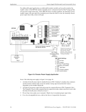
.... 34 HPF24S Series Power Supplies - The Normally Closed (when energized) power supervision relay contact must be installed between TB4, Terminals 5 & 6. For a list of -Line Resistor referred to in this figure, refer to the SLC manual appendix, which contains wiring conversion charts for module wiring supervision (the ELR value is lost, the Normally...
.... 34 HPF24S Series Power Supplies - The Normally Closed (when energized) power supervision relay contact must be installed between TB4, Terminals 5 & 6. For a list of -Line Resistor referred to in this figure, refer to the SLC manual appendix, which contains wiring conversion charts for module wiring supervision (the ELR value is lost, the Normally...