Installation Instructions
Page 1
... 2 Trouble/Alarm dry contact outputs type "Form C"; 1) Power Fail/ PTC Activated, and 2) FACP Triggered. When using larger batteries, a UL approved enclosure must be installed in compliance with Article 760 of two (2) Fire inputs, N/O or N/C, and Reverse Polarity triggered by Red LED ( L5 ). 17. Honeywell 12 Clintonville Road Northford, CT 06472 http://www.honeywellpower.com HP300ULM Access Control Power Supply/Charger...
... 2 Trouble/Alarm dry contact outputs type "Form C"; 1) Power Fail/ PTC Activated, and 2) FACP Triggered. When using larger batteries, a UL approved enclosure must be installed in compliance with Article 760 of two (2) Fire inputs, N/O or N/C, and Reverse Polarity triggered by Red LED ( L5 ). 17. Honeywell 12 Clintonville Road Northford, CT 06472 http://www.honeywellpower.com HP300ULM Access Control Power Supply/Charger...

Installation Instructions
Page 2
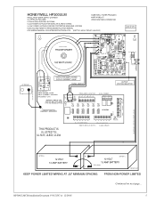
... (EOL) resistor. • Alarm Outputs - Connect the positive (+) and negative (-) from the FACP. L=Black (HOT), N=WHITE (Neutral), G=GREEN (Ground). Engineering Reset Input This option is available when the jumper JL is activated. - Continued on indication. • Fire Alarm Control Panel Input - Power Supply Input Connection Before connecting power review the entire wiring diagram for power on next page... 2 HP300ULMCB Installation Document P/N 52387:A 12/29/05 Output Connections...
... (EOL) resistor. • Alarm Outputs - Connect the positive (+) and negative (-) from the FACP. L=Black (HOT), N=WHITE (Neutral), G=GREEN (Ground). Engineering Reset Input This option is available when the jumper JL is activated. - Continued on indication. • Fire Alarm Control Panel Input - Power Supply Input Connection Before connecting power review the entire wiring diagram for power on next page... 2 HP300ULMCB Installation Document P/N 52387:A 12/29/05 Output Connections...
Installation Instructions
Page 3
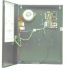
... or UL294 applications use the battery link provided to connect the two (2) 12 Volt Batteries in Fig 1. 6. PTC activated Yellow LED - Install the 2.2K Ohm (EOL) resistor provided at a Key Switch or Push Button to perform this manual reset operation and to supervise this will be connected together as shown in series. Alarm/Trouble Output a.) Power Fail: When DC Power fails or PTC activates...
... or UL294 applications use the battery link provided to connect the two (2) 12 Volt Batteries in Fig 1. 6. PTC activated Yellow LED - Install the 2.2K Ohm (EOL) resistor provided at a Key Switch or Push Button to perform this manual reset operation and to supervise this will be connected together as shown in series. Alarm/Trouble Output a.) Power Fail: When DC Power fails or PTC activates...
Installation Instructions
Page 4
... and the National Electrical Code. For continuous protection against hazard, replace fuses only with all connecting wiring. A readily accessible switched circuit breaker must be available to ensure the integrity of electric shock, do not expose unit to verify correct levels. Installation and servicing should only be routed so that it cannot touch 24V wiring; LED Test (distribution board only) - minimum...
... and the National Electrical Code. For continuous protection against hazard, replace fuses only with all connecting wiring. A readily accessible switched circuit breaker must be available to ensure the integrity of electric shock, do not expose unit to verify correct levels. Installation and servicing should only be routed so that it cannot touch 24V wiring; LED Test (distribution board only) - minimum...
Installation Instructions
Page 5
HP300ULMCB Installation Document P/N 52387:A 12/29/05 Continued on next page... 5
HP300ULMCB Installation Document P/N 52387:A 12/29/05 Continued on next page... 5
