User Manual
Page 1
September 2005 - Rev. 1.01 HJZTP/HJZTPX Joystick Controller for PTZ Cameras, DVRs, and Multiplexers User Manual 900.0570 -
September 2005 - Rev. 1.01 HJZTP/HJZTPX Joystick Controller for PTZ Cameras, DVRs, and Multiplexers User Manual 900.0570 -

User Manual
Page 5
....0570 8-Sept-05 d. f. HEAT - If liquid has been spilled, or objects have the same characteristics as an improper adjustment of other controls may damage the unit. When replacement parts are covered by the manufacturer or have fallen into the unit. This will often require extensive work ...hot or humid location, or in proper operating condition. 17. Exposure to rain or water may result in performance - Adjust only those controls that produce heat. 19. e. LIGHTNING AND POWER LINE SURGES - If the unit does not operate normally by a qualified technician to restore...
....0570 8-Sept-05 d. f. HEAT - If liquid has been spilled, or objects have the same characteristics as an improper adjustment of other controls may damage the unit. When replacement parts are covered by the manufacturer or have fallen into the unit. This will often require extensive work ...hot or humid location, or in proper operating condition. 17. Exposure to rain or water may result in performance - Adjust only those controls that produce heat. 19. e. LIGHTNING AND POWER LINE SURGES - If the unit does not operate normally by a qualified technician to restore...

User Manual
Page 7
... 3: SETUP ...11 3.1 KEYBOARD LOCK ...11 3.2 LCD DISPLAY...12 3.3 SYSTEM SETUP...13 3.3.1 3.3.2 3.3.3 Keyboard Type ...13 DVR/Multiplexer/Camera Connection 14 Dome (PTZ) Protocol...16 SECTION 4: DVR CONTROL FUNCTIONS 17 4.1 DVR MODE...17 4.2 NUMBER ENTRY (FOR ENTERING PASSWORDS 17 4.3 DVR MENUS ...17 4.4 PICTURE...
... 3: SETUP ...11 3.1 KEYBOARD LOCK ...11 3.2 LCD DISPLAY...12 3.3 SYSTEM SETUP...13 3.3.1 3.3.2 3.3.3 Keyboard Type ...13 DVR/Multiplexer/Camera Connection 14 Dome (PTZ) Protocol...16 SECTION 4: DVR CONTROL FUNCTIONS 17 4.1 DVR MODE...17 4.2 NUMBER ENTRY (FOR ENTERING PASSWORDS 17 4.3 DVR MENUS ...17 4.4 PICTURE...
User Manual
Page 8
... 5.2.1 5.2.2 5.2.3 Setup (Top) Menu...21 Bottom Menu ...22 Pop Up Menu...22 5.3 PICTURE CONTROL ...22 5.4 AUXILIARY MONITOR SELECTION 23 5.5 CAMERA SELECTION ...23 5.6 MULTIPLEXER SELECTION...24 SECTION 6: PTZ CONTROL FUNCTIONS WHEN USING HONEYWELL VCL (RAPIDDOME/ORBITER DOME) PROTOCOL...25 6.1 PTZ CAMERA SELECTION CONTROL 25 6.2 PTZ MODE ...25 6.3 PAN AND TILT...25 6.4 TURN 180°...25 6.5 ZOOM...
... 5.2.1 5.2.2 5.2.3 Setup (Top) Menu...21 Bottom Menu ...22 Pop Up Menu...22 5.3 PICTURE CONTROL ...22 5.4 AUXILIARY MONITOR SELECTION 23 5.5 CAMERA SELECTION ...23 5.6 MULTIPLEXER SELECTION...24 SECTION 6: PTZ CONTROL FUNCTIONS WHEN USING HONEYWELL VCL (RAPIDDOME/ORBITER DOME) PROTOCOL...25 6.1 PTZ CAMERA SELECTION CONTROL 25 6.2 PTZ MODE ...25 6.3 PAN AND TILT...25 6.4 TURN 180°...25 6.5 ZOOM...
User Manual
Page 9
...6.10.3.3 Camera Reset 32 Digital Zoom ...32 IR Lamps...33 Auto 180...33 Mimic Tour ...33 SECTION 7: PTZ CONTROL FUNCTIONS WHEN USING HONEYWELL DIAMOND (KD6/HD6) PROTOCOL...35 7.1 PTZ CAMERA SELECTION (HONEYWELL DIAMOND PROTOCOL 35 7.2 PTZ MODE ...35 7.3 PAN AND TILT...36 7.4 ZOOM...36 7.5 IRIS 36 7.6 FOCUS.........38 7.13 RETURN TO MANUAL ...38 7.14 MECHANICAL HOME ...38 7.15 ON SCREEN DISPLAY (OSD) MENUS 38 SECTION 8: PTZ CONTROL FUNCTIONS WHEN USING HONEYWELL MAXPRO MODE (KD6/HD6) PROTOCOL 41 8.1 INTRODUCTION ...41 8.2 RESET KD6I/HD6I...41 Rev. 1.01 ix 900.0570 8-Sept-05
...6.10.3.3 Camera Reset 32 Digital Zoom ...32 IR Lamps...33 Auto 180...33 Mimic Tour ...33 SECTION 7: PTZ CONTROL FUNCTIONS WHEN USING HONEYWELL DIAMOND (KD6/HD6) PROTOCOL...35 7.1 PTZ CAMERA SELECTION (HONEYWELL DIAMOND PROTOCOL 35 7.2 PTZ MODE ...35 7.3 PAN AND TILT...36 7.4 ZOOM...36 7.5 IRIS 36 7.6 FOCUS.........38 7.13 RETURN TO MANUAL ...38 7.14 MECHANICAL HOME ...38 7.15 ON SCREEN DISPLAY (OSD) MENUS 38 SECTION 8: PTZ CONTROL FUNCTIONS WHEN USING HONEYWELL MAXPRO MODE (KD6/HD6) PROTOCOL 41 8.1 INTRODUCTION ...41 8.2 RESET KD6I/HD6I...41 Rev. 1.01 ix 900.0570 8-Sept-05
User Manual
Page 10
...01 x 900.0570 8-Sept-05 DOME STAR WIRING CONFIGURATION 6 Figure 6. POWER CONNECTOR ...10 Figure 4. KBD/AUX/CONTROL CONNECTORS 9 Figure 3. DOME DAISY CHAIN CONFIGURATION 5 Figure 5. CONNECTION TO MULTIPLEXERS AND DVRS 7 Figure 7. TABLE OF CONTENTS, CONTINUED 8.3 CONTROLLING SCAN ASSEMBLIES 41 8.4 FREEZE / UNFREEZE VIDEO ...41 8.5 FLASHBACK OPERATION ...41 8.6 PRESHOTS ...42 8.7 VECTORSCANS (VIDEO... JOYSTICK AUTO CALIBRATION 49 B.2 KEY TEST...49 APPENDIX C: VCL (ORBITER/RAPIDDOME) DATA INPUT 51 APPENDIX D: PASSWORDS...53 LIST OF FIGURES Figure 1: HJZTP Rear Panel ...3 Figure 2.
...01 x 900.0570 8-Sept-05 DOME STAR WIRING CONFIGURATION 6 Figure 6. POWER CONNECTOR ...10 Figure 4. KBD/AUX/CONTROL CONNECTORS 9 Figure 3. DOME DAISY CHAIN CONFIGURATION 5 Figure 5. CONNECTION TO MULTIPLEXERS AND DVRS 7 Figure 7. TABLE OF CONTENTS, CONTINUED 8.3 CONTROLLING SCAN ASSEMBLIES 41 8.4 FREEZE / UNFREEZE VIDEO ...41 8.5 FLASHBACK OPERATION ...41 8.6 PRESHOTS ...42 8.7 VECTORSCANS (VIDEO... JOYSTICK AUTO CALIBRATION 49 B.2 KEY TEST...49 APPENDIX C: VCL (ORBITER/RAPIDDOME) DATA INPUT 51 APPENDIX D: PASSWORDS...53 LIST OF FIGURES Figure 1: HJZTP Rear Panel ...3 Figure 2.
User Manual
Page 11
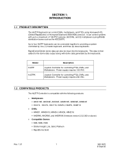
... can also be connected together to a maximum of 128 PTZ cameras, 99 DVRs, and 32 multiplexers (using Honeywell VCL (Orbiter/RapidDome) or Honeywell Diamond (KD6/HD6) protocol. Power supply requires 230 VAC. 1.2 COMPATIBLE PRODUCTS The HJZTP Controller is then added to the dome data output along with the following products: Multiplexers ...
... can also be connected together to a maximum of 128 PTZ cameras, 99 DVRs, and 32 multiplexers (using Honeywell VCL (Orbiter/RapidDome) or Honeywell Diamond (KD6/HD6) protocol. Power supply requires 230 VAC. 1.2 COMPATIBLE PRODUCTS The HJZTP Controller is then added to the dome data output along with the following products: Multiplexers ...
User Manual
Page 12
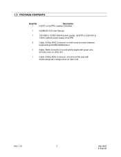
1.3 PACKAGE CONTENTS Quantity Description 1 HJZTP or HJZTPX Joystick Controller 1 HJZMU001150 User Manual 1 120 VAC to 12VDC 300mA power supply (HJZTP) or 230 VAC to 12VDC 300mA power supply (HJZTPX) 2 Cable, 8-Way RJ45 Connector on both ends (connect between keyboards and DVRs/Multiplexers) 1 Cable, RJ45 connector one end and fly leads with green wire and blue wire on other end 1 Cable, 8-Way RJ45 Connector one end and fly lead with white/orange and orange wires on other end Rev. 1.01 2 900.0570 8-Sept-05
1.3 PACKAGE CONTENTS Quantity Description 1 HJZTP or HJZTPX Joystick Controller 1 HJZMU001150 User Manual 1 120 VAC to 12VDC 300mA power supply (HJZTP) or 230 VAC to 12VDC 300mA power supply (HJZTPX) 2 Cable, 8-Way RJ45 Connector on both ends (connect between keyboards and DVRs/Multiplexers) 1 Cable, RJ45 connector one end and fly leads with green wire and blue wire on other end 1 Cable, 8-Way RJ45 Connector one end and fly lead with white/orange and orange wires on other end Rev. 1.01 2 900.0570 8-Sept-05

User Manual
Page 13
RS485 telemetry output - Master keyboard - slave keyboard - for connection to 12VDC 300mA power supply (supplied). Connection to PTZs (Honeywell domes) or RS485 distribution box. To connect either to the master keyboard, or a lower number slave keyboard. Rev. 1.01 ... to a DVR or a multiplexer. Slave keyboard - VCL dome data input to a slave keyboard. Connector KBD (RS485) AUX (RS485) CONTROL (RS485) POWER Figure 1: HJZTP Rear Panel Function Master keyboard - To connect to the RJ type connectors located on the rear panel of the unit. SECTION 2: INSTALLATION 2.1...
RS485 telemetry output - Master keyboard - slave keyboard - for connection to 12VDC 300mA power supply (supplied). Connection to PTZs (Honeywell domes) or RS485 distribution box. To connect either to the master keyboard, or a lower number slave keyboard. Rev. 1.01 ... to a DVR or a multiplexer. Slave keyboard - VCL dome data input to a slave keyboard. Connector KBD (RS485) AUX (RS485) CONTROL (RS485) POWER Figure 1: HJZTP Rear Panel Function Master keyboard - To connect to the RJ type connectors located on the rear panel of the unit. SECTION 2: INSTALLATION 2.1...
User Manual
Page 14
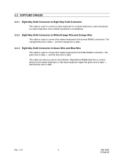
... keyboard to a multiplexer. 2.2.2 Eight-Way RJ45 Connector to White/Orange Wire and Orange Wire This cable is used to input Orbiter / RapidDome RS485 data from a control device to the master keyboard, or last slave keyboard. The green wire is data +, and the blue wire is used to connect the master keyboard...
... keyboard to a multiplexer. 2.2.2 Eight-Way RJ45 Connector to White/Orange Wire and Orange Wire This cable is used to input Orbiter / RapidDome RS485 data from a control device to the master keyboard, or last slave keyboard. The green wire is data +, and the blue wire is used to connect the master keyboard...
User Manual
Page 17
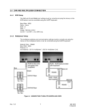
... 2 etc. 2.4.2 Multiplexer Setup The multiplexer address and communication settings must be correctly set using the menus on the DVR before it can be controlled using the HJZTP keyboard. Remote control Unit ID - 1 for DVR 1, 2 for multiplexer 2 etc Rev. 1.01 Figure 6. 2.4 DVR AND MULTIPLEXER CONNECTION 2.4.1 DVR Setup The DVR unit ID and RS485 port...
... 2 etc. 2.4.2 Multiplexer Setup The multiplexer address and communication settings must be correctly set using the menus on the DVR before it can be controlled using the HJZTP keyboard. Remote control Unit ID - 1 for DVR 1, 2 for multiplexer 2 etc Rev. 1.01 Figure 6. 2.4 DVR AND MULTIPLEXER CONNECTION 2.4.1 DVR Setup The DVR unit ID and RS485 port...

User Manual
Page 18
... communicate with any DVR, multiplexer, or dome connected to the master. 2.5.1 Master/Slave Connection A system of cascaded keyboards is being input into the system from a control device. In the above system two slave keyboards are connected to the multiplexer / DVR and dome RS485 line. Figure 7. The system also has two multiplexers...
... communicate with any DVR, multiplexer, or dome connected to the master. 2.5.1 Master/Slave Connection A system of cascaded keyboards is being input into the system from a control device. In the above system two slave keyboards are connected to the multiplexer / DVR and dome RS485 line. Figure 7. The system also has two multiplexers...
User Manual
Page 21
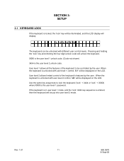
...1.01 11 900.0570 8-Sept-05 XXXX is the user level 1 unlock code. (Code not shown) 3434 is unlocked with different user control levels. User level 2 allows limited control of the keyboard to lock the keyboard ('lock' + 3434 or 'lock' + XXXX) where XXXX is the user level 1 password. When... the keyboard is unlocked with user level 2 control, 'U2' will display: L OCKE D The keyboard can be unlocked with user level 1 control, 'U1' will be displayed on the LCD. SECTION 3: SETUP 3.1 KEYBOARD LOCK If the keyboard is locked, the '...
...1.01 11 900.0570 8-Sept-05 XXXX is the user level 1 unlock code. (Code not shown) 3434 is unlocked with different user control levels. User level 2 allows limited control of the keyboard to lock the keyboard ('lock' + 3434 or 'lock' + XXXX) where XXXX is the user level 1 password. When... the keyboard is unlocked with user level 2 control, 'U2' will display: L OCKE D The keyboard can be unlocked with user level 1 control, 'U1' will be displayed on the LCD. SECTION 3: SETUP 3.1 KEYBOARD LOCK If the keyboard is locked, the '...

User Manual
Page 22
... then their displayed camera may not always be a camera which the keyboard is controlling the multiplexers spot monitor number n. When the keyboard is controlling the multiplexers main monitor 'MAIN' will be different to the controlled camera. 'DVR nn' is the DVR which is being displayed, as it ...is possible to send Diamond protocol. 'Un' is the user control level. 'U1' means the keyboard is in user level 1 control mode, 'U2', means the keyboard is in multiplexer control mode then the display will be as shown below: C A ME R A PRESET nnn nnn MU X ...
... then their displayed camera may not always be a camera which the keyboard is controlling the multiplexers spot monitor number n. When the keyboard is controlling the multiplexers main monitor 'MAIN' will be different to the controlled camera. 'DVR nn' is the DVR which is being displayed, as it ...is possible to send Diamond protocol. 'Un' is the user control level. 'U1' means the keyboard is in user level 1 control mode, 'U2', means the keyboard is in multiplexer control mode then the display will be as shown below: C A ME R A PRESET nnn nnn MU X ...
User Manual
Page 24
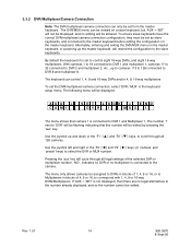
...keyboards. 3.3.2 DVR/Multiplexer/Camera Connection Note: The DVR/multiplexer/camera connection can only be allowed. Rev. 1.01 14 900.0570 8-Sept-05 The keyboard can control 1, 4, 9 and 16-way DVRs and/or 4, 9, 16-way multiplexers To set from the master keyboard. If 'AUX = SET' is connected to DVR... not displayed, then there are no editing will be set the DVR/multiplexer/camera connection, select 'DVR / MUX' in blocks of 1, 4, 9 or 16, or to control eight 16-way DVRs, and eight 16-way multiplexers. The following menu will be displayed: AUX = C A M1 S E T L OCK = E ND DVR 1 MU...
...keyboards. 3.3.2 DVR/Multiplexer/Camera Connection Note: The DVR/multiplexer/camera connection can only be allowed. Rev. 1.01 14 900.0570 8-Sept-05 The keyboard can control 1, 4, 9 and 16-way DVRs and/or 4, 9, 16-way multiplexers To set from the master keyboard. If 'AUX = SET' is connected to DVR... not displayed, then there are no editing will be set the DVR/multiplexer/camera connection, select 'DVR / MUX' in blocks of 1, 4, 9 or 16, or to control eight 16-way DVRs, and eight 16-way multiplexers. The following menu will be displayed: AUX = C A M1 S E T L OCK = E ND DVR 1 MU...
User Manual
Page 26
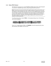
Once the required protocol has been selected, press 'lock' to control RapidDome/Orbiter type domes using Honeywell VCL protocol or KD6/HD6 type domes using Honeywell Diamond protocol. 3.3.3 Dome (PTZ) Protocol The keyboard can be set up the master keyboard will re-send the protocol setting to toggle between 'VCL' and '...
Once the required protocol has been selected, press 'lock' to control RapidDome/Orbiter type domes using Honeywell VCL protocol or KD6/HD6 type domes using Honeywell Diamond protocol. 3.3.3 Dome (PTZ) Protocol The keyboard can be set up the master keyboard will re-send the protocol setting to toggle between 'VCL' and '...
User Manual
Page 27
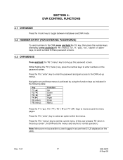
...' or 'alarm' keys, to send numbers to there password screens. 4.3 DVR MENUS Press and hold the 'Fn' key, then press the number keys. SECTION 4: DVR CONTROL FUNCTIONS 4.1 DVR MODE Press the 'mode' key to toggle between multiplexer and DVR mode. 4.2 NUMBER ENTRY (FOR ENTERING PASSWORDS) To send numbers to the DVR...
...' or 'alarm' keys, to send numbers to there password screens. 4.3 DVR MENUS Press and hold the 'Fn' key, then press the number keys. SECTION 4: DVR CONTROL FUNCTIONS 4.1 DVR MODE Press the 'mode' key to toggle between multiplexer and DVR mode. 4.2 NUMBER ENTRY (FOR ENTERING PASSWORDS) To send numbers to the DVR...

User Manual
Page 28
...of the DVRs displayed camera(s) by the 'camera' key to select that number camera to be displayed in that number camera for picture control: Key display sequence freeze Function Display Sequence Freeze Press the 'display' key to enter a legal camera number) followed by putting the keyboard...camera selection by pressing the 'F5' ('enter') key, then 'F1' (''), 'F2' (''), 'F3' ('') or 'F4' ('') keys to control. Rev. 1.01 18 900.0570 8-Sept-05 Press the 'sequence' key to select that cameo. This also selects the associated DVR. This also selects the...
...of the DVRs displayed camera(s) by the 'camera' key to select that number camera to be displayed in that number camera for picture control: Key display sequence freeze Function Display Sequence Freeze Press the 'display' key to enter a legal camera number) followed by putting the keyboard...camera selection by pressing the 'F5' ('enter') key, then 'F1' (''), 'F2' (''), 'F3' ('') or 'F4' ('') keys to control. Rev. 1.01 18 900.0570 8-Sept-05 Press the 'sequence' key to select that cameo. This also selects the associated DVR. This also selects the...
User Manual
Page 31
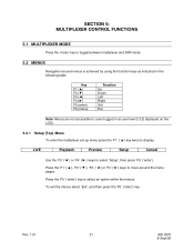
... within the menus. Rev. 1.01 21 900.0570 8-Sept-05 To exit the menus select 'Exit', and then press the 'F5' ('enter') key. SECTION 5: MULTIPLEXER CONTROL FUNCTIONS 5.1 MULTIPLEXER MODE Press the 'mode' key to toggle between multiplexer and DVR mode. 5.2 MENUS Navigation around the menu pages.
... within the menus. Rev. 1.01 21 900.0570 8-Sept-05 To exit the menus select 'Exit', and then press the 'F5' ('enter') key. SECTION 5: MULTIPLEXER CONTROL FUNCTIONS 5.1 MULTIPLEXER MODE Press the 'mode' key to toggle between multiplexer and DVR mode. 5.2 MENUS Navigation around the menu pages.
User Manual
Page 32
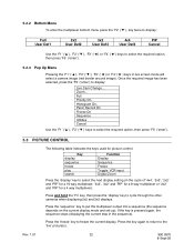
... the cycle of '4x4', '3x3', '2x2' and 'PIP' for a 16 way multiplexer, '3x3', '2x2' and 'PIP' for a 9 way multiplexer or '2x2' and 'PIP' for picture control: Key display sequence freeze play search Function Display Sequence Freeze Toggle VCR input Digital Zoom Press the 'display' key to select the next display setting...(s). Panic Record On Freeze On Sequence Utilities Cancel Use the 'F1' ('▲'), 'F2' ('▼') keys to select the required option, then press 'F5' ('enter'). 5.3 PICTURE CONTROL The following table indicates the keys used for a 4 way multiplexer).
... the cycle of '4x4', '3x3', '2x2' and 'PIP' for a 16 way multiplexer, '3x3', '2x2' and 'PIP' for a 9 way multiplexer or '2x2' and 'PIP' for picture control: Key display sequence freeze play search Function Display Sequence Freeze Toggle VCR input Digital Zoom Press the 'display' key to select the next display setting...(s). Panic Record On Freeze On Sequence Utilities Cancel Use the 'F1' ('▲'), 'F2' ('▼') keys to select the required option, then press 'F5' ('enter'). 5.3 PICTURE CONTROL The following table indicates the keys used for a 4 way multiplexer).