Brochure
Page 1
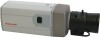
...). For additional installation flexibility the unit can also be powered with hybrid Digital Video Recorders (DVRs) and Network Video Recorders (NVRs). Features • 4CIF, 2CIF, or CIF resolutions • 1/3" color CCD, 540 TVL • Excellent low light performance, down to 0.4 lux • Camera Sabotage Detection • MPEG-4 compression • Remote firmware updates • Supports both indoor and outdoor applications. HCD554IP EQUIP® SERIES TRUE DAY/NIGHT NETWORK CAMERA www.honeywellvideo.com Honeywell's EQUIP® Series is quick and easy...
...). For additional installation flexibility the unit can also be powered with hybrid Digital Video Recorders (DVRs) and Network Video Recorders (NVRs). Features • 4CIF, 2CIF, or CIF resolutions • 1/3" color CCD, 540 TVL • Excellent low light performance, down to 0.4 lux • Camera Sabotage Detection • MPEG-4 compression • Remote firmware updates • Supports both indoor and outdoor applications. HCD554IP EQUIP® SERIES TRUE DAY/NIGHT NETWORK CAMERA www.honeywellvideo.com Honeywell's EQUIP® Series is quick and easy...
Brochure
Page 2
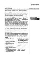
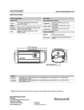
HCD554IP SPECIFICATIONS Like all camera settings. This ensures the video's integrity and alerts the customer to the video stream. Honeywell's technology also allows users to remotely upload firmware to the camera's video and network setup. System Diagram Internet Explorer or Honeywell IT Utility NETWORK EQUIP SERIES CAMERAS Hybrid DVR or NVR NETWORK EQUIP SERIES CAMERAS Workstation Hybrid DVR Monitor NVR Monitors Keyboard Monitors Set-up is causing disruption to either a live event or a system problem that is quick and easy and can be customized through a Web client...
HCD554IP SPECIFICATIONS Like all camera settings. This ensures the video's integrity and alerts the customer to the video stream. Honeywell's technology also allows users to remotely upload firmware to the camera's video and network setup. System Diagram Internet Explorer or Honeywell IT Utility NETWORK EQUIP SERIES CAMERAS Hybrid DVR or NVR NETWORK EQUIP SERIES CAMERAS Workstation Hybrid DVR Monitor NVR Monitors Keyboard Monitors Set-up is causing disruption to either a live event or a system problem that is quick and easy and can be customized through a Web client...
Brochure
Page 3
... variable bit rate (MPEG-4) Security Multiple user access levels with password protection Users 1 Administrator, 4 Guests (unicast) Video Access from Web Browser Camera live view for up to administrator Minimum Web Browsing Requirements Pentium IV CPU 3.0 GHz or equivalent AMD, 512 MB RAM, AGP graphics card (32 MB RAM) Windows® XP 2000, Internet Explorer 6.0 or later Supported Protocols IPv4, HTTP, TCP, RTSP, RTP, UDP, ARP, DNS, RTCP, FTP, ICMP, DHCP, Bonjour...
... variable bit rate (MPEG-4) Security Multiple user access levels with password protection Users 1 Administrator, 4 Guests (unicast) Video Access from Web Browser Camera live view for up to administrator Minimum Web Browsing Requirements Pentium IV CPU 3.0 GHz or equivalent AMD, 512 MB RAM, AGP graphics card (32 MB RAM) Windows® XP 2000, Internet Explorer 6.0 or later Supported Protocols IPv4, HTTP, TCP, RTSP, RTP, UDP, ARP, DNS, RTCP, FTP, ICMP, DHCP, Bonjour...
Brochure
Page 4
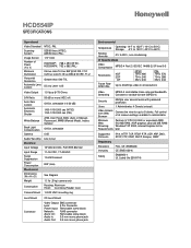
... Auto Iris Lens, IR Corrected Housing and Mounts HBC5WT HHC12 Series Wall/ceiling mount bracket Housing with optional heater/blower and mounts 2.44" (62.00 mm) 2.44" (62.00 mm) 5.70" (145.00 mm) 1.24" (31.50 mm) 2.65" (67.22 mm) VIDEO ETHERNET AUDIO IN OUT 0.81" (20.70 mm) Ordering HCD554IP HCD554IPX EQUIP Series 1/3" CCD High Resolution True Day/Night Camera with DSP, 540 TVL, 12 VDC...
... Auto Iris Lens, IR Corrected Housing and Mounts HBC5WT HHC12 Series Wall/ceiling mount bracket Housing with optional heater/blower and mounts 2.44" (62.00 mm) 2.44" (62.00 mm) 5.70" (145.00 mm) 1.24" (31.50 mm) 2.65" (67.22 mm) VIDEO ETHERNET AUDIO IN OUT 0.81" (20.70 mm) Ordering HCD554IP HCD554IPX EQUIP Series 1/3" CCD High Resolution True Day/Night Camera with DSP, 540 TVL, 12 VDC...
User Manual
Page 3
... Functions 14 Installation 14 Selecting the Lens 14 Adjusting the Back Focus 15 Mounting the Camera 15 Wiring 16 Connecting Video 16 Connecting Power 17 Connecting Alarms 18 Connecting Audio 20 Restore Factory Defaults 20 3 Configuring Network Settings 21 Preparing the Honeywell IP Utility 21 System Requirements 21 Installing the IP Utility 22 Uninstalling the IP Utility 22 User Profiles 23 Logging On to the IP Utility 23 Changing the User Password 24 User Interface 25 IP Camera Network Configuration 26...
... Functions 14 Installation 14 Selecting the Lens 14 Adjusting the Back Focus 15 Mounting the Camera 15 Wiring 16 Connecting Video 16 Connecting Power 17 Connecting Alarms 18 Connecting Audio 20 Restore Factory Defaults 20 3 Configuring Network Settings 21 Preparing the Honeywell IP Utility 21 System Requirements 21 Installing the IP Utility 22 Uninstalling the IP Utility 22 User Profiles 23 Logging On to the IP Utility 23 Changing the User Password 24 User Interface 25 IP Camera Network Configuration 26...
User Manual
Page 4
... On 33 Installing Honeywell IP (ActiveX Plug-in 34 Logging Off 35 Uninstalling Honeywell IP (ActiveX Plug-in 35 Navigating the User Interface 36 Live View 37 Device Settings 37 Compression Settings 39 Compression Settings 40 Audio Settings 40 Camera Setup 40 Auto Exposure 41 White Balance 42 Video Analytics 43 Video Blurring 44 Camera Blinding 45 Camera Field of View Change 46 Appendix A Troubleshooting 47 Technical Support 47 Problem: Web-Client Does Not Display the Expected Video 47 Problem: Cannot Connect to...
... On 33 Installing Honeywell IP (ActiveX Plug-in 34 Logging Off 35 Uninstalling Honeywell IP (ActiveX Plug-in 35 Navigating the User Interface 36 Live View 37 Device Settings 37 Compression Settings 39 Compression Settings 40 Audio Settings 40 Camera Setup 40 Auto Exposure 41 White Balance 42 Video Analytics 43 Video Blurring 44 Camera Blinding 45 Camera Field of View Change 46 Appendix A Troubleshooting 47 Technical Support 47 Problem: Web-Client Does Not Display the Expected Video 47 Problem: Cannot Connect to...
User Manual
Page 5
... 19 Alarm Output Connection 19 IP Utility Login Screen 24 IP Utility Change Password Dialog Box 24 IP Utility User Interface 25 IP Network Settings Obtained Automatically 27 IP Network Settings Obtained Manually 28 IP Utility Firmware Upgrade 29 Changing Web-Client User Passwords 30 Internet Options 32 Security Settings 33 Logon Screen 34 Honeywell IP Installation (ActiveX Plug-in 35 Web-Client: Administrator User 36 Web-Client: Guest User 37 Device Settings 38 Compression Settings 39 Camera Setup 41 Video Analytics 44 Video Analytics Message 44 ActiveX Control...
... 19 Alarm Output Connection 19 IP Utility Login Screen 24 IP Utility Change Password Dialog Box 24 IP Utility User Interface 25 IP Network Settings Obtained Automatically 27 IP Network Settings Obtained Manually 28 IP Utility Firmware Upgrade 29 Changing Web-Client User Passwords 30 Internet Options 32 Security Settings 33 Logon Screen 34 Honeywell IP Installation (ActiveX Plug-in 35 Web-Client: Administrator User 36 Web-Client: Guest User 37 Device Settings 38 Compression Settings 39 Camera Setup 41 Video Analytics 44 Video Analytics Message 44 ActiveX Control...
User Manual
Page 7
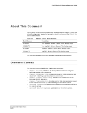
EQUIP Series IP Camera Reference Guide About This Document This document introduces the Honeywell Color Day/Night Network Camera. See Table 0-1 for system installers, administrators, and operators. Table 0-1 Model Number HCD554IP HCD554IPX HCS554IP HCS554IPX Network Camera Model Numbers Description True Day/Night Network Camera, NTSC, Analog output True Day/Night Network Camera, PAL, Analog output Day/Night Network Camera, NTSC, Analog output Day/Night Network Camera, PAL, Analog output This document is used to install, configure and operate the camera in a network environment. ...
EQUIP Series IP Camera Reference Guide About This Document This document introduces the Honeywell Color Day/Night Network Camera. See Table 0-1 for system installers, administrators, and operators. Table 0-1 Model Number HCD554IP HCD554IPX HCS554IP HCS554IPX Network Camera Model Numbers Description True Day/Night Network Camera, NTSC, Analog output True Day/Night Network Camera, PAL, Analog output Day/Night Network Camera, NTSC, Analog output Day/Night Network Camera, PAL, Analog output This document is used to install, configure and operate the camera in a network environment. ...

User Manual
Page 13
... clearest image • Set up cameras in a network system Before you Begin Please read this guide carefully before you install the network camera. 2 Installation and Setup This chapter describes how to this User Guide: • One fully-assembled network camera • 3-pin terminal block for Power input • 4-pin terminal block for Alarm input/output • One product warranty • One CD containing the software If any parts are...
... clearest image • Set up cameras in a network system Before you Begin Please read this guide carefully before you install the network camera. 2 Installation and Setup This chapter describes how to this User Guide: • One fully-assembled network camera • 3-pin terminal block for Power input • 4-pin terminal block for Alarm input/output • One product warranty • One CD containing the software If any parts are...

User Manual
Page 15
... focus the picture. 3. Figure 2-1 Back Focus Adjustment Setscrews Lens connector for a spacer ring. Adjust the focus ring at the front end of the camera housing to accept standard sized mounting bolts (1/4 x 20). Document 800-00250 Rev C 15 08/08 They are used without the need for Auto Iris lens Focus ring Reset button restores factory default settings 1. EQUIP Series IP Camera Reference Guide Adjusting the Back Focus The back focus adjustment is accessible at the front end of the camera housing...
... focus the picture. 3. Figure 2-1 Back Focus Adjustment Setscrews Lens connector for a spacer ring. Adjust the focus ring at the front end of the camera housing to accept standard sized mounting bolts (1/4 x 20). Document 800-00250 Rev C 15 08/08 They are used without the need for Auto Iris lens Focus ring Reset button restores factory default settings 1. EQUIP Series IP Camera Reference Guide Adjusting the Back Focus The back focus adjustment is accessible at the front end of the camera housing...

User Manual
Page 16
Connecting Video Spot Monitor The analog video connection is available as a test output and should be in accordance with all national and local mechanical and electrical codes. Installation and Setup Figure 2-2 Camera Mount Use standard size mounting bolts (1/4 x 20) to mount the camera on your spot monitor. 16 Caution Installation must be performed by a qualified service technician and must be used during installation to position and aim the camera as needed. Wiring Figure 2-3 Camera Connections 24 VAC...
Connecting Video Spot Monitor The analog video connection is available as a test output and should be in accordance with all national and local mechanical and electrical codes. Installation and Setup Figure 2-2 Camera Mount Use standard size mounting bolts (1/4 x 20) to mount the camera on your spot monitor. 16 Caution Installation must be performed by a qualified service technician and must be used during installation to position and aim the camera as needed. Wiring Figure 2-3 Camera Connections 24 VAC...

User Manual
Page 17
... 2 power supply is receiving power. Plug in the power supply. Connect the camera to a power supply appropriate for your network camera will automatically be made through the network cable. 2. The RJ-45 jack LED briefly illuminates to a PC or laptop using an Ethernet (10Base-T, 100Base-TX) cable. EQUIP Series IP Camera Reference Guide Network RJ-45 Ethernet Connection The main video connection for your installation: • 12 VDC or 24 VAC power supply (proceed to step 2) • Power over Ethernet) compatible...
... 2 power supply is receiving power. Plug in the power supply. Connect the camera to a power supply appropriate for your network camera will automatically be made through the network cable. 2. The RJ-45 jack LED briefly illuminates to a PC or laptop using an Ethernet (10Base-T, 100Base-TX) cable. EQUIP Series IP Camera Reference Guide Network RJ-45 Ethernet Connection The main video connection for your installation: • 12 VDC or 24 VAC power supply (proceed to step 2) • Power over Ethernet) compatible...

User Manual
Page 18
... that the camera is receiving power. Connect either connector terminal. 3. The network camera has one alarm input and one alarm output available to connect to either power lead to peripheral devices (Figure 2-4). 18 Note For secure installations, surface mounted cables should be considered to maintain 12 VDC/24 VAC at the same time. If it does not illuminate, check the removable terminal block connections and the power source. The LED on alarm output connections.
... that the camera is receiving power. Connect either connector terminal. 3. The network camera has one alarm input and one alarm output available to connect to either power lead to peripheral devices (Figure 2-4). 18 Note For secure installations, surface mounted cables should be considered to maintain 12 VDC/24 VAC at the same time. If it does not illuminate, check the removable terminal block connections and the power source. The LED on alarm output connections.

User Manual
Page 21
... the network and enables you can configure the IP network settings, name the camera(s), upgrade the firmware, and change the user passwords of the device. Note Before installing and using the Honeywell IP Utility, make sure that your network through an Ethernet cable (see Network RJ-45 Ethernet Connection on a work station that meets the following minimum requirements: Table 3-1 PC Minimum System Requirements Component Operating System Processor RAM Web Browser Requirement Windows®...
... the network and enables you can configure the IP network settings, name the camera(s), upgrade the firmware, and change the user passwords of the device. Note Before installing and using the Honeywell IP Utility, make sure that your network through an Ethernet cable (see Network RJ-45 Ethernet Connection on a work station that meets the following minimum requirements: Table 3-1 PC Minimum System Requirements Component Operating System Processor RAM Web Browser Requirement Windows®...

User Manual
Page 23
... to viewing network settings, there are no such restrictions. Open Add or Remove Programs and then select Honeywell IP Utility in at a time • Can enable/disable a device's Web-Client • View the list of devices available on the network • Connect to the devices • Configure the IP network settings • Upgrade the firmware version • Change the password for the IP Utility application • Change the password for the Web-Client...
... to viewing network settings, there are no such restrictions. Open Add or Remove Programs and then select Honeywell IP Utility in at a time • Can enable/disable a device's Web-Client • View the list of devices available on the network • Connect to the devices • Configure the IP network settings • Upgrade the firmware version • Change the password for the IP Utility application • Change the password for the Web-Client...
User Manual
Page 29
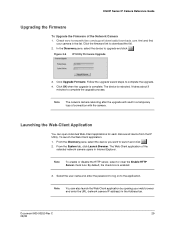
... Utility Firmware Upgrade 3. Click Upgrade Firmware. Follow the upgrade wizard steps to upgrade and click . Launching the Web-Client Application You can also launch the Web-Client application by opening your camera in Internet Explorer. Document 800-00250 Rev C 29 08/08 Check www.honeywellvideo.com/support/downloads/downloads_cam.html and find your web browser and enter the URL (network camera IP address) in a temporary loss of connection with the camera...
... Utility Firmware Upgrade 3. Click Upgrade Firmware. Follow the upgrade wizard steps to upgrade and click . Launching the Web-Client Application You can also launch the Web-Client application by opening your camera in Internet Explorer. Document 800-00250 Rev C 29 08/08 Check www.honeywellvideo.com/support/downloads/downloads_cam.html and find your web browser and enter the URL (network camera IP address) in a temporary loss of connection with the camera...
User Manual
Page 43
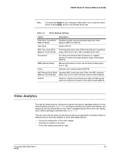
... camera, blurring the video display, and tampering with fluorescent or tungsten lighting. Table 4-5 White Balance Settings Option Description ATW (Auto Trace White Feedback system that when the following conditions are applicable, the tamper detection features must be manually disabled to detect three types of view. Outdoor Preset for your new settings will be configured to avoid raising false alarms: • during the configuration of all the time. Video Analytics The network camera...
... camera, blurring the video display, and tampering with fluorescent or tungsten lighting. Table 4-5 White Balance Settings Option Description ATW (Auto Trace White Feedback system that when the following conditions are applicable, the tamper detection features must be manually disabled to detect three types of view. Outdoor Preset for your new settings will be configured to avoid raising false alarms: • during the configuration of all the time. Video Analytics The network camera...
User Manual
Page 47
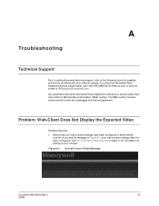
.... A Troubleshooting Technical Support Prior to calling Honeywell technical support, refer to the following topics for warranty or service repair must be clearly marked on setting up your web browser settings have been configured to Honeywell Video Systems for possible solutions to HVSsupport@honeywell.com. The RMA number must have not been configured). Any equipment returned to allow ActiveX controls (if you see the message in Figure A-1, your network camera. Ensure...
.... A Troubleshooting Technical Support Prior to calling Honeywell technical support, refer to the following topics for warranty or service repair must be clearly marked on setting up your web browser settings have been configured to Honeywell Video Systems for possible solutions to HVSsupport@honeywell.com. The RMA number must have not been configured). Any equipment returned to allow ActiveX controls (if you see the message in Figure A-1, your network camera. Ensure...
User Manual
Page 49
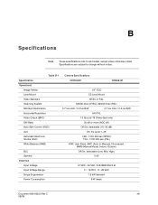
... models, except where otherwise noted. Table B-1 Camera Specifications Specification Operational Image Sensor Lens Mount Video Standard Scanning System Minimum Illumination Horizontal Resolution Video Output (BNC) S/N Ratio Auto Gain Control (AGC) ALC Automatic Electronic Shutter (ELC) White Balance (AWB) BLC Gamma Electrical Input Voltage Input Voltage Range Surge Suppression Power Consumption HCD554IP HCS554IP 1/3" CCD CS Lens Mount NTSC or PAL 525/60 lines (NTSC), 625/50 lines (PAL) 0.7 lux color / 0.2 lux B/W 0.7 lux color...
... models, except where otherwise noted. Table B-1 Camera Specifications Specification Operational Image Sensor Lens Mount Video Standard Scanning System Minimum Illumination Horizontal Resolution Video Output (BNC) S/N Ratio Auto Gain Control (AGC) ALC Automatic Electronic Shutter (ELC) White Balance (AWB) BLC Gamma Electrical Input Voltage Input Voltage Range Surge Suppression Power Consumption HCD554IP HCS554IP 1/3" CCD CS Lens Mount NTSC or PAL 525/60 lines (NTSC), 625/50 lines (PAL) 0.7 lux color / 0.2 lux B/W 0.7 lux color...

User Manual
Page 50
... connector Lens: 4 Pin connector Power Input: Removable screw terminal block Alarm I/O: Removable screw terminal block Network: RJ45 connector Operating: 14°F to 122°F (-10°C to +50°C) Storage: -4° to 140°F (-20°C to 60°) 0% to 30/25 fps video in all camera settings available to 5 clients. Specifications Table B-1 Specification IP Specifications Video Compression Resolutions Frame Rate (NTSC/PAL) Video Streaming Security Users Video access from web browser Minimum web browsing requirements Supported Protocols...
... connector Lens: 4 Pin connector Power Input: Removable screw terminal block Alarm I/O: Removable screw terminal block Network: RJ45 connector Operating: 14°F to 122°F (-10°C to +50°C) Storage: -4° to 140°F (-20°C to 60°) 0% to 30/25 fps video in all camera settings available to 5 clients. Specifications Table B-1 Specification IP Specifications Video Compression Resolutions Frame Rate (NTSC/PAL) Video Streaming Security Users Video access from web browser Minimum web browsing requirements Supported Protocols...


